Tag: SALUS
-

SALUS T105 Programmable Thermostat Wiring Daigram
SALUS T105 Programmable Thermostat Wiring Diagram Wiring diagram LEGEND Battery Operated 230V AC power supply Fuse COM, NO, NC Voltage-free output contacts S, S1, S2Entrance designation SL 230V AC voltage output Contact normally open Contact normally closed NC/COM/NO switch Boiler – Boiler connection * – Boiler’s contacts for ON/OFF thermostat (according to the boiler’s instructions) Wireless…
-

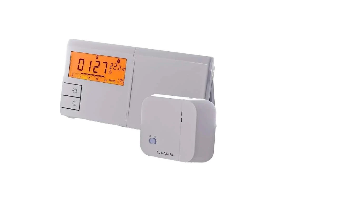
SALUS RT510SPE Wireless Programmable thermostat Wiring Diagram
SALUS RT510SPE Wireless Programmable thermostat Wiring diagram LEGEND Battery powered 230V AC power supply Fuse COM, NO, NC Voltage-free output S, S1, S2 Input terminals SL 230V AC voltage output Contact normally open Contact normally closed NC/COM/NO switch Boiler – Boiler connection * – Boiler’s contacts for ON/OFF thermostat (according to the boiler’s instructions) Wireless…
-

SALUS RT510SR Wireless Programmable thermostat Wiring Diagram
SALUS RT510SR Wireless Programmable thermostat Wiring diagram LEGEND Battery powered L, N 230V AC power supply Fuse COM, NO, NC Voltage free output S, S1, S2 Input terminals SL 230V AC voltage output Contact normally open Contact normally closed NC/COM/NO switch Boiler – Boiler connection * – Boiler’s contacts for ON/OFF thermostat (according to the…
-

SALUS RT510SPE Wireless Programmable Thermostat Quick Guide
SALUS RT510SPE Wireless Programmable Thermostat Introduction The RT510SPE module will switch your appliance on or off in accordance with the temperature set by you. The completed RT510SPE series consists of a transmitter – RT510TX thermostat and a Smart Plug SPE868. Go to www.salus-manuals.com for the full PDF version of the manual. Product Compliance This product…
-

SALUS RT310TX Non-Programmable Thermostat Quick Guide
SALUS RT310TX Non-Programmable Thermostat Introduction RT310 / RT310RF is a digital room thermosat used to control room temperature. Device launching heating system by shorting terminal blocks, simultaneously informing the action and showing this information on the LCD display. Before use please read this manual carefully. Use only AA 1.5 V alkaline batteries in the thermostat.…
-

SALUS HTRP24(50) Programmable Thermostat Quick Guide
SALUS HTRP24(50) Programmable Thermostat Introduction The HTRP24V(50) from SALUS Controls is a stylish and accurate 5/2 or 24h programmable electronic thermostat with a large, easy-to-read Liquid Crystal Display (LCD). It is a surface-mounted temperature controller dedicated for surface heating/cooling, characterized by high thermal inertia. It is connected to the wired wiring center KL08NSB. The thermostat…
-

SALUS HTR24(20) Wired Non-Programmable Thermostat Quick Guide
SALUS HTR24(20) Wired Non-Programmable Thermostat Introduction HTR230(20) is a surface-mounted (or on a flush-box) room thermostat dedicated for surface heating/cooling control, characterized by high thermal inertia. It is connected to the wiring centre, through which you can lower the set temperature on it, receiving a signal NSB (night temperature reduction) from the weekly thermostat. The…
-

SALUS HTR24(20) wired Non-Programmable Thermostat Wiring Diagram
SALUS HTR24(20) wired Non-Programmable Thermostat Wiring diagram LEGEND Battery powered 230V AC power supply Fuse Voltage free output Input terminals 230V AC voltage output Contact normally open Contact normally closed NC/COM/NO switch Boiler – Boiler connection * – Boiler’s contacts for ON/OFF thermostat (according to the boiler’s instructions) Wireless communication Pump Valve actuator Temperature sensor…
-
SALUS HTR230(20) wired Non-Programmable Thermostat Quick Guide
SALUS HTR230(20) wired Non-Programmable Thermostat Introduction HTR230(20) is a surface-mounted (or on a flush-box) room thermostat dedicated for surface heating / cooling control, characterized by high thermal inertia. It is connected to the wiring centre, through which you can lower the set temperature on it, receiving a signal NSB (night temperature reduction) from the weekly…
-
SALUS HTR230(20) Wired Non-Programmable Thermostat Wiring Diagram
SALUS HTR230(20) Wired Non-Programmable Thermostat Wiring diagram LEGEND Battery powered 230V AC power supply Fuse Voltage free output Input terminals 230V AC voltage output Contact normally open Contact normally closed NC/COM/NO switch Boiler – Boiler connection * – Boiler’s contacts for ON/OFF thermostat (according to the boiler’s instructions) Wireless communication Pump Valve actuator Temperature sensor…
-

SALUS ERT2024V Non-Programmable Thermostat Quick Guide
SALUS ERT2024V Non-Programmable Thermostat Electronic room temperature controller for panel, radiator and convection heating systems General Congratulations on choosing a SALUS brand room thermostat. In selecting the ERT20 model you have chosen an electronic room temperature controller which offers key advantages over conventional mechanical products: The controller is easy to operate using the conventional backlit…
-

SALUS ERT2024V Non-Programmable Thermostat Wiring Diagram
SALUS ERT2024V Non-Programmable Thermostat Wiring diagram LEGEND Battery powered 230V AC power supply Fuse Voltage free output Input terminals 230V AC voltage output Contact normally open Contact normally closed NC/COM/NO switch Boiler – Boiler connection * – Boiler’s contacts for ON/OFF thermostat (according to the boiler’s instructions) Wireless communication Pump Valve actuator Temperature sensor 3-speed…
-

SALUS BTR230(20) Non-Programmable Thermostat Quick Guide
SALUS BTR230(20) Non-Programmable Thermostat Introduction The BTR230 is an electronic flush mount Room Thermostat for Bezel 55, which offers key advantages over conventional mechanical products. Product Compliance This product complies with 2014/30/EU, 2014/35/EU, 2011/65/EU. Full text of the EU Declaration of Conformity on www.saluslegal.com. Safety Information Use in accordance with the regulations. Indoor use only.…
-
SALUS BTR230(20) Non-Programmable Thermostat Wiring Diagram
SALUS BTR230(20) Non-Programmable Thermostat Wiring diagram LEGEND Battery powered 230V AC power supply Fuse Voltage free output Input terminals 230V AC voltage output Contact normally open Contact normally closed NC/COM/NO switch Boiler – Boiler connection * – Boiler’s contacts for ON/OFF thermostat (according to the boiler’s instructions) Wireless communication Pump Valve actuator Temperature sensor 3-speed…
-
SALUS 091FLRFV2 Programmable Wireless Thermostat Wiring Diagram
SALUS 091FLRFV2 Programmable Wireless Thermostat Wiring diagram LEGEND Battery powered 230V AC power supply Fuse Voltage free output Input terminals 230V AC voltage output Contact normally open Contact normally closed NC/COM/NO switch Boiler – Boiler connection * – Boiler’s contacts for ON/OFF thermostat (according to the boiler’s instructions) Wireless communication Pump Valve actuator Temperature sensor…
-

SALUS 091FLRFV2 Programmable Wireless Thermostat Quick Guide
SALUS 091FLRFV2 Programmable Wireless Thermostat Introduction 091FLv2/091FLRFv2 is a programmable, weekly thermostat used to control room temperature in heating or cooling systems. Before use please read this manual carefully. Use only AA 1.5V alkaline batteries in the thermostat. Place the batteries into the battery slot located under the cover. Do not use rechargeable batteries. Product…
-
SALUS 091FLV2 Wired Programmable Thermostat Wiring Diagram
SALUS 091FLV2 Wired Programmable Thermostat Wiring diagram LEGEND Battery powered 230V AC power supply Fuse Voltage free output Input terminals 230V AC voltage output Contact normally open Contact normally closed NC/COM/NO switch Boiler – Boiler connection * – Boiler’s contacts for ON/OFF thermostat (according to the boiler’s instructions) Wireless communication Pump Valve actuator Temperature sensor…
-

SALUS 091FLV2 wired Programmable Thermostat Quick Guide
SALUS 091FLV2 wired Programmable Thermostat Introduction 091FLv2/091FLRFv2 is a programmable, weekly thermostat used to control room temperature in heating or cooling systems. Before use please read this manual carefully. Use only AA 1.5V alkaline batteries in the thermostat. Place the batteries into the battery slot located under the cover. Do not use rechargeable batteries. Product…
-

SALUS IT500 Internet Thermostat Wiring Diagram
SALUS IT500 Internet Thermostat Wiring diagram LEGEND Battery powered 230V AC power supply Fuse Voltage free output Input terminals 230V AC voltage output Contact normally open Contact normally closed NC/COM/NO switch Boiler – Boiler connection * – Boiler’s contacts for ON/OFF thermostat (according to the boiler’s instructions) Wireless communication Pump Valve actuator Temperature sensor 3-speed…
-

SALUS IT500 Internet thermostat Quick Guide
SALUS IT500 Internet thermostat Introduction The iT500 controls your heating and hot water from anywhere via your smartphone or laptop. Your pc and laptop connects to the system using existing broadband connection. The system is wireless so it’s easy to instal. FEATURES: Access and control your heating and hot water via the internet Compatible with…
-

SALUS WT100 Weather Thermostat User Manual
SALUS WT100 Weather Thermostat SAFETY INFORMATION Requirements concerning safety are listed in particular sections of this instruction. Apart from them it in necessary to fulfill the following requirements. Prior to starting the assembly, repairs or maintenance and during the execution of any connection works, it is necessary to switch off the mains supply and make…
-

SALUS VS35 Wired digital Non-Programmable thermostat Wiring Daigram
SALUS VS35 Wired digital Non-Programmable thermostat Wiring diagram LEGEND Battery powered 230V AC power supply Fuse Voltage free output Input terminals 230V AC voltage output Contact normally open Contact normally closed NC/COM/NO switch Boiler – Boiler connection * – Boiler’s contacts for ON/OFF thermostat (according to the boiler’s instructions) Wireless communication Pump Valve actuator Temperature…
-

SALUS VS35 Wired Digital Non-Programmable Thermostat User Manual
SALUS VS35 Wired Digital Non-Programmable Thermostat Introduction Product Compliance This product complies with the essential requirements and other relevant provisions of Directives 2014/53/EU and 2011/65/EU. The full text of the EU Declaration of Conformity is available at the following internet address: www.saluslegal.com. Safety Informations Before starting installation work and before using the product, read the…
-
SALUS VS35 Wired Digital Non-Programmable Thermostat Quick Guide
SALUS VS35 Wired digital Non-Programmable thermostat Terminals description Terminal Description L,N Power Supply 230 V AC NSB Night SetBack (input 230 V AC) SL Switched output (230 V AC) S1, S2 External temperature sensor Proper thermostat placement Button Functions LCD Icon description Current active mode Comfort mode Standard mode Economic mode Automatic mode Frost protection…
-

SALUS VS30 Wired digital thermostat Wiring Diagram
SALUS VS30 Wired digital thermostat Wiring diagram LEGEND Battery powered 230V AC power supply Fuse Voltage free output Input terminals 230V AC voltage output Contact normally open Contact normally closed NC/COM/NO switch Boiler – Boiler connection * – Boiler’s contacts for ON/OFF thermostat (according to the boiler’s instructions) Wireless communication Pump Valve actuator Temperature sensor…
-

SALUS VS30 Wired Digital Thermostat Quick Guide
SALUS VS30 Wired Digital Thermostat Introduction The VS30 thermostat controls temperatures of individual heating zone in underfloor heating systems. The thermostat allows for significant savings thanks to the possibility of maximum reduction the set temperature. The full version of the manual in PDF format is available on the website www.salus-controls.eu Product Compliance This product complies…
-
SALUS VS30 Wired digital thermostat User Manual
SALUS VS30 Wired digital thermostat Introduction Product Compliance This product complies with the essential requirements and other relevant provisions of Directives 2014/53/EU and 2011/65/EU. The full text of the EU Declaration of Conformity is available at the following internet address: www.saluslegal.com. Safety Informations Before starting installation work and before using the product, read the entire…
-
SALUS VS20BRF Wireless Digital Thermostat Wiring Diagram
SALUS VS20BRF Wireless Digital Thermostat Wiring diagram LEGEND Battery powered 230V AC power supply Fuse Voltage free output Input terminals 230V AC voltage output Contact normally open Contact normally closed NC/COM/NO switch Boiler – Boiler connection * – Boiler’s contacts for ON/OFF thermostat (according to the boiler’s instructions) Wireless communication Pump Valve actuator Temperature sensor…
-
SALUS VS20BRF Wireless digital thermostat Quick Guide
SALUS VS20BRF Wireless digital thermostat Introduction VS10..RF / VS20..RF is a room temperature thermostat that is used for wireless control of iT600 series devices such as: KL08RF wiring centre, TRV radiator valve and RX10RF boiler receiver. In combination with Universal Gateway UGE600 this regulator can be controlled over the Internet using SALUS Smart Home app…
-
SALUS VS10BRF Wireless Digital Thermostat Quick Guide
SALUS VS10BRF Wireless Digital Thermostat Introduction VS10..RF / VS20.RF is a room temperature thermostat that is used for wireless control of iT600 series devices such as: the KL08RF wiring center, TRV radiator valve and RX10RF boiler receiver. In combination with Universal Gateway UGE600, this regulator can be controlled over the Internet using the SALUS Smart…