
SALUS HTR24(20) Wired Non-Programmable Thermostat

Introduction
HTR230(20) is a surface-mounted (or on a flush-box) room thermostat dedicated for surface heating/cooling control, characterized by high thermal inertia. It is connected to the wiring centre, through which you can lower the set temperature on it, receiving a signal NSB (night temperature reduction) from the weekly thermostat. The room temperature could be set by knob use. Thanks to the built-in algorithms, it offers much better temperature control accuracy than traditional mechanical thermostats. The thermostat is characterized by silent operation.
Product compliance
The product complies with the following EU directives: 2014/30/EU, 2014/35/EU, 2011/65/EU. Full information is available at www.saluslegal.com
Note!
This document is a quick guide to the installation and operation of the product and indicates its main features and functions. Detailed information is available in the full manual, which is available at www.salus-controls.eu and must be used for proper installation and operation of the product.
SAFETY INFORMATIONS:
Use in accordance with national and EU regulations. Use the device as intended and keep it dry. Product for indoor use only. Please read the entire manual before starting the installation and using the product.
INSTALLATION:
Installation must be carried out by a qualified person, with appropriate electrical authorisations, in accordance with national and EU standards and regulations. The manufacturer shall not be liable for failure to comply with the manual.
NOTE:
There may be additional protection requirements for the entire installation. The installer shall be responsible for compliance with such requirements.
Package content
Proper thermostat location
The ideal position to thermostat mounting is about 1,5m under floor level far from heating or cooling sources. In addition, the thermostat should not be installed behind curtains or other obstacles or in places with high humidity, as this will prevent accurate measurements of room temperature. The thermostat must not be exposed to sunlight. Do not place the thermostat on an outer wall.
Connection description
Note:The thermostat is compatibile with the following Salus wiring centre models: KL06 230V, KL08NSB 230V, KL04NSB 230V or directly to the actuator.

Symbols explanation:
| Terminal | Description |
| L, N | Power supply (24V AC) |
| Night temperature reduction (24V output) | |
| 24 V AC output signal | |
| CO | Switching jumper between heating and cooling (input 24V AC) |
Note: The following designations are used interchangeably for products:
 = SL
= SL = NSB
= NSB
Montage
Make sure that the thermostat is not connected to the 24V AC. Remove the knob by pulling it towards you, and then open the front cover as shown in the figure above.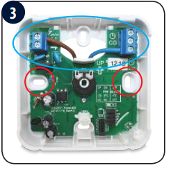
Connect the thermostat. Please refer to the “Connection Description” section. Mount the thermostat using the designed screw holes.
Fold front and back housing of the thermostat. The thermostat is configured. Use the knob to set the temperature setpoint.
Jumpers for additional settings
The functions of the HTR230(20) thermostat can be switched on and off by jumpers. Please refer to the table below:

Jumpers 1 to 5 correspond to the number of actuators connected. This jumper is factory set to position 1, which means that the thermostat controls one actuator. Depending on the number of actuators used, the jumper position must be changed to ensure optimal operation of the temperature thermostat.
Selecting the heating or cooling mode
Heating or cooling mode is based on the voltage sent to the CO terminal. 0V AC at the CO terminal – the thermostat is in heating mode. 230V AC at the CO contact – the thermostat is in cooling mode.
Cooling blocking function
Cooling on:
Set the jumper to ON ![]() . The thermostat will work in cooling mode if 230V AC will appear at the CO terminal. The LED lights up blue when the thermostat sends a signal for cooling.
. The thermostat will work in cooling mode if 230V AC will appear at the CO terminal. The LED lights up blue when the thermostat sends a signal for cooling.
Night setback – NSB function
The NSB (Night Set Back) function enables automatic reduction of the temperature setpoint on the daily thermostats, via the programmable thermostat connected to the wiring centre. The temperature change takes place between day and night temperatures. When the night mode is activated, the programmable thermostat sends a voltage signal to the daily thermostats via the wiring centre. Then, the HTR230(20) thermostat automatically reduces the temperature setpoint on the knob by 2° or 4° (as set on the SETBACK jumper). In heating mode, the temperature is lowered when 230 V AC voltage appears at the NSB input.
Note: For the proper NSB function work, an appropriate cable connection is required. TThe connection description is on the previous page.
Valve Protection
Set the jumper to ON – ![]() to enable or OFF –
to enable or OFF – ![]() to disable the function. This function activates the thermostatic valve for 5 minutes once a week to prevent valve against stuck (caused by limescale).
to disable the function. This function activates the thermostatic valve for 5 minutes once a week to prevent valve against stuck (caused by limescale).
Operation algorithm selection
The thermostat gives the possibility to choose the mode of controlling the room temperature by PWM algorithm (default) or hysteresis +/-0.5°C. The PWM algorithm is designed for underfloor heating (for heating systems with high inertia) – to precisely maintain the room temperature.
Technical information
| Power supply | 24V AC 50 Hz |
| Max. load | TRIAC 0.5 A |
| Output signal | 24V AC 50 Hz |
| Temperature control range | 5 – 30°C |
| Control method | PWM or Hysteresis: ±0.5°C |
| Communication | Wired |
| Dimension [mm] | 85 x 85 x 30 |
SALUS CONTROLS DISTRIBUTOR:
QL CONTROLS Sp. z o.o., Sp. k.
ul. Rolna 4,
43-262 Kobielice,
Poland
Importer:
SALUS Controls Plc
Units 8-10 Northfield Business Park Forge Way, Parkgate
Rotherham S60 1SD United Kingdom
www.salus-controls.eu
SALUS Controls is a member of the Computime Group.
In accordance with the product development policy, SALUS Controls plc reserves the right to change specifications, design, and materials used in production, presented in this manual, without prior notice.
REFERENCE
Download Manual:
SALUS HTR24(20) wired Non-Programmable Thermostat Quick Guide
OTHER MANUALS
SALUS HTR24(20) wired Non-Programmable Thermostat Wiring Diagram
SALUS HTR24(20) Wired Non-Programmable Thermostat Quick Guide