
SALUS VS10BRF Wireless Digital Thermostat

Introduction
VS10..RF / VS20.RF is a room temperature thermostat that is used for wireless control of iT600 series devices such as: the KL08RF wiring center, TRV radiator valve and RX10RF boiler receiver. In combination with Universal Gateway UGE600, this regulator can be controlled over the Internet using the SALUS Smart Home app (Online mode). Without an Internet connection (Offline mode) thermostat works locally, but its communication with other devices must be done through the coordinating unit – CO10RF. The full version of the PDF manual instruction is available on the website www.salus-controls.eu
Product Compliance
EC Directives: 2014/30/EU, 2014/35/EU, 2014/53/EU i 2011/65/EU.
Full information is available on the website www.saluslegal.com
Safety Information
Use in accordance to national and EU regulations. Use the device as intended, keeping it in dry condition. Product for indoor use only.
Installation must be carried out by a qualified person in accordance to national and EU regulations.
Wiring diagram
VS10WRF (white), VS10BRF (black)


- Power Supply: 230V AC (L, N terminals)
- 1, 2 Terminals:
- external air or floor temperature sensor
- external contact (occupancy sensor)
- external hot water thermostat (only with KL10RF configuration)
- Montage: 60mm concealed box
VS20WRF (white), VS20BRF (black)

- Power Supply: 4xAAA (alkaline batteries)
- S1, S2 Terminals:
- external air or floor temperature sensor
- external contact (occupancy sensor)
- external hot water thermostat (only with KL10RF configuration)
- Montage: surface mounting (need to remove back cover)
LCD Icon Description

- Comfort temperature
- Standard temperature
- Economic temperature
- Automatic mode
- PARTY mode
- Holiday mode
- Antifrost mode
- Temperature unit
- Group controller
- Manual mode / override temp.
- Current / set temperature
- Program number
- AM / PM
- Lock function
- Clock
- Day indicator
- Settings
- Low battery indicator
- External temperature sensor
- Hot water heating
- Modes for Hot Water (KL10RF only)
- Cooling mode ON
- Internet connection indicator
- Gateway wireless connection
- Heating mode ON

Select the type of ZigBee coordinator
Choose a ZigBee coordinator and prepare it to work with iT600 series devices:
- Online – connected to the Internet via the UGE600 gateway

or - Offline -the ability to connect to the Internet using the UGE600 gateway

or - Offline – without Internet connection with CO10RF coordinator

Firstly with the selected coordinator need to install devices, which will be controlled by thermostat. Pairing method of each devices is described in the manual instruction of a particular device.

Installation
first, start up

The thermostat starts up in a simplified configuration mode. You can choose to pair it with:
 KL08RF or KL10RF wiring center (underfloor heating)
 Thermostatic radiator valve (radiator heating)
Note: Thermostat is set by default as programmable (weekly).
extended configuration
If the simplified configuration is not suitable, run the expanded configuration by holding 3 keys as below until SEL PROG appears:

Set the thermostat type:
 Programmable (weekly)
 Daily
Daily Hot Water timer (works only with KL10RF)
After approval of the type of thermostat, choose the type of device to cooperate with:
pairing with KL08RF / KL10RF wiring centre
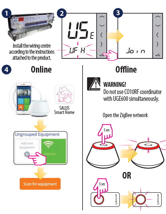


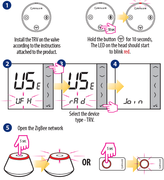
Pairing thermostat with TRV in Online mode
WARNING! You can connect up to 6 heads to one thermostat


Pairing thermostat with TRV in Offline mode
WARNING! You can connect up to 6 heads to one thermostat.


Pairing thermostat with RX10RF boiler receiver
- Install the RX10RF boiler receiver according to the instructions attached to the product. Choose proper mode configuration with RX1/RX2 switch inside of RX10RF, then prepare the regulator for pairing.

WARNING! In network coordinator can works only with 1 receiver in RX1 mode and 1 receiver in RX2 mode. - Run thermostat in extended configuration mode and select the device type:
- RX10RF in RX1 mode
- RX10RF in RX2 mode


Identification of paired devices
Enter the installer mode, select code “00” and confirm it with the button.

Temperature change
To set the temperature, press ![]() , and then confirm it with the button.
, and then confirm it with the button.

Note: If the thermostat works in AUTO mode, then the overwritten temperature will be maintained until next program. In manual mode and antifrost mode temperature change is permanent.
Factory Reset
If you have made an error, need to change your thermostat parameters or want to return to the factory settings, please follow steps below.
Note: This action will permanently remove all your settings.

Distributor: QL CONTROLS Sp. z o.o., Sp.k.
Importer:
Rolna 4, 43-262 Kobielice, Poland www.salus-controls.eu
SALUS Controls Plc Units 8-10 Northfield Business Park Forge Way, Parkgate, Rotherham S60 1SD, United Kingdom
Reference
Download Manual
SALUS VS10BRF Wireless Digital Thermostat Quick Guide
OTHER MANUALS
SALUS VS10BRF Wireless digital thermostat User Manual
SALUS VS10BRF Wireless digital thermostat Wiring Daigram
![]()