SALUS VS35 Wired Digital Non-Programmable Thermostat

Introduction
Product Compliance
This product complies with the essential requirements and other relevant provisions of Directives 2014/53/EU and 2011/65/EU. The full text of the EU Declaration of Conformity is available at the following internet address: www.saluslegal.com.
Safety Informations
- Before starting installation work and before using the product, read the entire manual.
- The information contained in the instructions is essential for proper functioning.
- To avoid accidents resulting in personal injury and material damage, please follow all safety precautions, specified in this manual.
- The device should not be used by people with limited mental, sensory or mental abilities, without experience, of insufficient knowledge as well as children.
- Do not use an unassembled device (eg without a cover).
- The device may only be opened by a qualified person.
- Keep electrical devices out of the reach of children and ensure that they do not play with it. Children should not be left unattended. If necessary, disconnect the control system for the entire room.
- Do not leave the packaging, cabinet, or any loose parts of the device unattended, as they pose a risk to children.
WARNING!
- Installation must be carried out by a qualified person with appropriate electrical qualifications in accordance with standards and regulations in force in the given country and in the EU.
- Never try to connect the device other than as described in the manual.
- Before assembly, repair or maintenance as well as during any connection works it is absolutely necessary disconnect the mains supply and make sure that the terminals and electric wires are not live.
- The device may not be exposed to extreme temperatures, strong vibrations or subjected to mechanical shock.
- The device should not be used in unfavorable environmental conditions or in rooms where there is a concentration of flammable gases, fumes or dust.
- There may be additional protection requirements for the entire installation that the installer is responsible for maintaining.
Care for the natural environment is of paramount importance to us. The awareness that we manufacture electronic devices obliges us to dispose of used electronic components and devices safely. Therefore the company has received a registration number issued by the Chief Inspector for Environmental Protection. The crossed out symbol the trash can on the product means that the product must not be disposed of with ordinary waste containers. Sorting waste for recycling helps to protect the environment. It is the user’s responsibility to surrender used equipment to a designated collection point for recycling waste from electrical and electronic equipment.
Product Overview
The VS30W/VS30B from SALUS Controls is a stylish and accurate 5/2 or 24h programmable electronic thermostat with a large, easy to read Liquid Crystal Display (LCD). It is flush-mounted temperature controller dedicated for surface heating / cooling, characterized by high thermal inertia. It is connected to the wired wiring centre KL08NSB. Thermostat has the function of creating your own schedules. It can control group (SLAVE) thermostats – via wiring centre it sends them an NSB (nighttime temperature reduction) signal and switches them to economic temperature. The time schedule is common to all thermostats (according to weekly (MASTER) thermostat), but temperatures are set individually on each thermostat.
The programmable room thermostat VS30W/VS30B is both a programmer and a room thermostat. A programmer allows you to set ‘ON’ and ‘OFF’ time periods to suit your own lifestyle. A room thermostat works by sensing the air temperature, switching on the heating when the air temperature falls below the thermostat setting and switching it off once this set temperature has been reached.
So, a programmable room thermostat lets you choose what times you want the heating to be on, and what temperature it should reach while it is on. It will allow you to select different temperatures in your home at different times of the day (and days of the week) to meet your particular needs.
Turning a programmable room thermostat to a higher setting will not make the room heat up any faster. How quickly the room heats up depends on the design of the heating system, for example, the size of boiler. Neither does the setting affect how quickly the room cools down. Turning a programmable room thermostat to a lower setting will result in the room being controlled at a lower temperature, and saves energy.
The way to set and use your programmable room thermostat is to find the lowest temperature settings that you are comfortable with at the different times you have chosen, and then leave it alone to do its job. The best way to do this is to set low temperatures first, say 18°C, and then turn them up by one degree each day until you are comfortable with the temperatures. You won’t have to adjust the thermostat further. Any adjustments above these settings will waste energy and cost you more money.
PRODUCT ADVANTAGES:
- has a PWM control algorithm
- protection against too high or too low temperature using an additional FS300 floor sensor
- valve protection function
- an input for the additional temperature sensor
- has frost protection mode
- working with actuators of both types – NC and NO
- mounting in a φ 60 mm wall box
Montage
Package content

- VS30W/VS30B thermostat
- Short instruction
- Mounting screws
Proper thermostat location
Please note:
The ideal position to thermostat mounting is about 1,5m under floor level far from heating or cooling sources. The thermostat can’t be exposed to sunlight or any extreme conditions like for example draft.
Because of fire and explosion risk there is not allowed to use the thermostat in an atmosphere of explosive gases and flammable liquids (eg coal dust). In case if any of listed dangers occur you have to use additional protection measures – anti-dust and explosive gases (tight cover) or prevent their formation. Furthermore, thermostats can’t be used in condensation of water vapor conditions and be exposed to water action.
Wall mounting
Mounting: to mount the thermostat you can use accesories included with the set (mounting screws). Remove back cover to mount the plate to the wall. After this just attach thermostat to the plate right into designed holes in the plate. The VS30 thermostat has been designed for flush mounting in a standard electrical box with a diameter of 60 mm.

Connection description

A – 4 wire installation with KL08NSB wiring center
When VS30W/VS30B thermostat works as a MASTER (group controller) it means it takes control of SLAVE thermostats e.g. VS35W. MASTER thermostat controls SLAVE thermostat only when SLAVE thermostat is in AUTO mode. Comfort (SUN) and economy (MOON) setpoint temperatures are set individually on each thermostat but switching between those temperature is based on time schedule taken from VS30W/VS30B thermostat which works like a group controller. Functions such as: setpoint temperature change, holiday mode, party mode or frost protection mode are not managed by MASTER thermostat.


B – 4 wire installation with KL06 wiring center


Pump and boiler logic module (for KL06) connection diagram

3-wire installation with KL08NSB wiring center
3-wire installation with KL08NSB wiring center. Description of the operation rules:
- VS30W/VS30B thermostat’s functionality is limited because of 3 wire installation. NSB function is disabled and VS30W/VS30B thermostat doesn’t work as a MASTER thermostat – no effect on other thermostats like VS35W/VS35B.
- schedules can be set individually on each VS30W/VS30B thermostat if system is equipped with more than one VS30W/VS30B thermostat.
PLEASE NOTE!
The same operating rules apply to wiring center KL06.


- A – work with RM-16A relay module – volt-free heating source control

- B – work with RM-16A relay module – connection to a solid fuel boiler controller
 PLEASE NOTE! Activate the thermostat in the solid fuel boiler controller.
 - C – work with RM-16A relay module – connecting an electrical device with a higher power than the thermostat relay allows
PLEASE NOTE! The maximum current consumption of an electrical device should not exceed 16A.

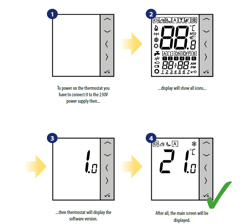
Before you start (first power up)

- Current active mode
- Comfort mode
- Standard mode
- Economic mode
- Automatic mode
- Frost protection mode
- Temperature unit
- Manual mode / temp. override
- Current / set temperature
- Key lock
- Settings
- Additional temperature sensor
- Cooling
- Heating

PLEASE NOTE! The LCD screen can be activated by using any button.
First power up sequence
Work modes
VS35W/VS35B offers a few work modes. Frame on a given icon indicates which mode is currently active. In manual mode ,
,![]() or
or ![]() only one temperature level is maintained. VS35W/VS35B follows MASTER thermostat when AUTO mode is active („A” icon) – please refer to 2.5 connection description chapter. Detailed description of work modes is located below:
only one temperature level is maintained. VS35W/VS35B follows MASTER thermostat when AUTO mode is active („A” icon) – please refer to 2.5 connection description chapter. Detailed description of work modes is located below:
 Frame – means that the work mode is active (the icon of the work mode must be in the center of the frame). For example:
 means that comfort temperature mode is active
 means that comfort temperature mode is inactive
- Comfort temperature mode – pre-defined setpoint temperature. Usually set when we are indoors. The highest maintained temperature in heating mode or the lowest if thermostat works in the cooling system. Acting alone works as a manual mode. Temperature range: from 5°C to 35°C.
 Standard temperature mode – pre-defined setpoint temperature. Usually set during the day when we are around the house. Acting alone works as a manual mode.
 Economic temperature mode – pre-defined setpoint temperature. Usually set at night or when we are out of the house. Acting alone works as a manual mode. Temperature range: from 5°C to 35°C.
 Automatic mode temperature (schedule) – follows a programmed schedule. Schedule can be temporarily overridden with new setpoint temperature (temporary override mode will be active to the next change forced by the schedule,
  hand icon will be displayed).
 Frost protection mode – usually used during extended periods of absence or during the holidays (only available in heating mode). Temperature range: from 5°C to 17°C.
Example – comfort temperature mode setpoint editing:

User settings (basic settings)
Thermostat calibration
Thermostat calibration is a function which allows user to recalibrate internal thermostat’s temperature sensor by a given number of degrees (in the range from -3,0 °C to 3,0 °C in 0,5 °C steps). To calibrate thermostat’s temperature sensor please follow steps below:

Heat/cool mode change
Installer parameters
To enter installer parameters please follow steps below. Please refer to parameters table description before any changes. Use or buttons to move up or down between all parameters. Every change/selection confirm by button:

| dXX | Function | Parameter Values | Description | Default Values |
|
d01 |
Control method temperature |
This parameter defines the algorithm of the room temperature control. |
0 |
|
|
0 |
PWM (Pulse-width modulation) algorithm ensures reduction of overdrive states and economic operation of the system. It is an advanced algorithm designed to precisely maintain room temperature. | |||
| 1 | SPAN ± 0.25°C | |||
| 2 | SPAN ± 0.5°C | |||
|
d02 |
Offset temperature |
-3.0°C to
+ 3.0°C |
Offset room temperature measuring is a function which allows user to recalibrate internal thermostat’s temperature sensor by a given number of degrees (in the range from -3,0 °C to 3,0 °C in 0,5°C steps). |
0.0°C |
|
d03 |
Using a floor temperature sensor (S1, S2) | 0 | No sensor |
0 |
| 1 | Sensor is connected | |||
| dXX | Function | Parameter Values | Description | Default Values |
|
d04 |
External sensor used for air or floor temperature measurement (Function is active, when d03=1) | 0 | Thermostat measures the temperature only on the external sensor |
0 |
| 1 | The sensor is used as a protection against overheating the floor | |||
|
d05 |
Cooling mode control method | 1 | Span ±0.5°C |
2 |
| 2 | Span ±1.0°C | |||
|
d06 |
Type of thermoelectric actuator |
0 | NO – normally open |
1 |
| 1 | NC – normally closed | |||
|
d07 |
Valve Protection |
0 |
Enable/Disable.
Valve protection function is intended to protect thermostatic valves against getting stuck or jamming (e.g. in summer time when heating system is disabled). If thermostat doesn’t send a signal for heating for a period of 7 days, then heating is turned on for a very short period of time just to move the actuators. |
1 |
|
1 |
||||
|
d08 |
Frost protection temperature |
5°C – 17°C |
In Frost protection mode the thermostat is displaying actual room temperature and maintain„frost protection” setpoint temperature specified in thermostat settings. When thermostat works in Frost protection mode then you have no possibilities to change temperature setpoint. |
5.0°C |
| d12 | Heating temperature limit | 5°C – 35°C | The maximum heating temperature that can be set by the user | 35°C |
| d13 | Cooling temperature limit | 5°C – 40°C | The minimum cooling temperature that can be set by the user | 5°C |
|
d14 |
Maximum floor temperature (this function is active
in heating mode when d04 = 1) |
6-45°C |
In order to protect the floor from overheating, heating will be turned OFF, when the maximum temperature of the floor sensor will be reached |
27°C |
|
d15 |
Minimum floor temperature (this function is active
in heating mode when d04 = 1) |
6-45°C |
In order to protect the floor, heating will be turned ON, when the minimum temperature of the floor sensor will be reached |
10°C |
|
d16 |
Lower floor temperature limit for cooling (this function is active when d04 = 1) |
6-45°C |
In order to protect the floor, cooling will be turned OFF, when the minimum temperature will be reached |
6°C |
|
d18 |
Operating mode HEATING / COOLING |
0 | Heating system |
0 |
| 1 | Cooling system |
Factory Reset
To RESET VS35W/VS35B thermostat to it’s factory default settings please follow steps below:


Error codes
The thermostat constantly monitors the operation of connected sensors. If it detects any failure then following error codes can be displayed.

|
Error code |
ERROR DESCRIPTION |
TROUBLESHOOTING |
|
Err02 |
The maximum / minimum floor temperature has been exceeded |
• Set the heating / cooling medium temperature or change D14 / D15 parameter. |
|
Err03 |
Floor sensor is faulty |
• If floor sensor is connected to S1/S2 input, check the wiring.
• If floor sensor is not connected, check the D03/D04 parameters settings. |
|
Err04 |
Floor sensor is shorted |
• Check floor sensor wire insulation for any damages. Sensor resistance for 25°C=10kΩ. |
Cleaning and Maintenance
The VS35W/VS35B thermostat requires no special maintenance. Periodically, the outer casing can be wiped clean using a dry cloth (please DO NOT use solvents, polishes, detergents or abrasive cleaners, as these can damage the thermostat). There are no user serviceable parts within the unit; any servicing or repairs could only be carried out by Salus Controls or their appointed agents.
Technical Informations
| Power supply | 230 V AC 50 Hz |
| Rating max | 3 A |
| Switched output | 230 V AC 50 Hz |
| Temperature range | 5°C – 35°C |
| Dimensions | 86mm x 86mm x 42mm |

Warranty
SALUS Controls warrants that this product will be free from any defect in materials or workmanship, and shall perform in accordance with its specification, for a period of five years from the date of installation. SALUS Controls sole liability for breach of this warranty will be (at its option) to repair or replace the defective product. 
DISTRIBUTOR OF SALUS CONTROLS:
QL CONTROLS Sp. z o.o., Sp. k. Rolna 4, 43-262 Kobielice, Poland
IMPORTER:
SALUS Controls Plc Units 8-10 Northfield Business Park Forge Way, Parkgate Rotherham S60 1SD United Kingdom
SALUS Controls is a member of the Computime Group.
Maintaining a policy of continuous product development SALUS Controls plc reserves the right to change the specification, design, and materials of products listed in this brochure without prior notice.
Reference
Download Manual
SALUS VS35 Wired Digital Non-Programmable Thermostat User Manual
OTHER MANUALS
SALUS VS35 Wired digital Non-Programmable thermostat Quick Guide
SALUS VS35 Wired digital Non-Programmable thermostat Wiring Daigram
![]()
SALUS VS35 Wired Digital Non-Programmable Thermostat User Manual