SALUS T105 Programmable Thermostat Wiring Daigram

SALUS T105 Programmable Thermostat Wiring Diagram Wiring diagram LEGEND Battery Operated 230V AC power supply Fuse COM, NO, NC Voltage-free output contacts S, S1, S2Entrance designation SL 230V AC voltage output Contact normally open Contact normally closed NC/COM/NO switch Boiler – Boiler connection * – Boiler’s contacts for ON/OFF thermostat (according to the boiler’s instructions) Wireless […]
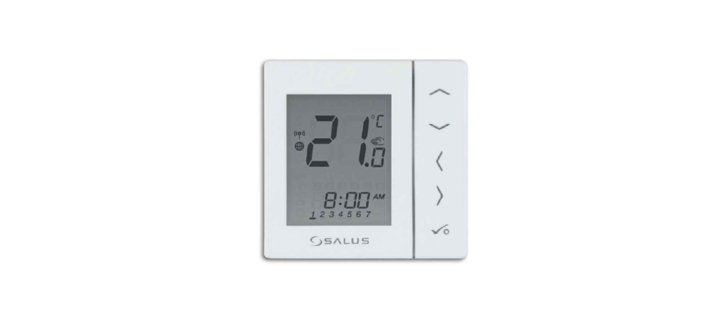
SALUS RT510SPE Wireless Programmable thermostat Wiring Diagram

SALUS RT510SPE Wireless Programmable thermostat Wiring diagram LEGEND Battery powered 230V AC power supply Fuse COM, NO, NC Voltage-free output S, S1, S2 Input terminals SL 230V AC voltage output Contact normally open Contact normally closed NC/COM/NO switch Boiler – Boiler connection * – Boiler’s contacts for ON/OFF thermostat (according to the boiler’s instructions) Wireless […]
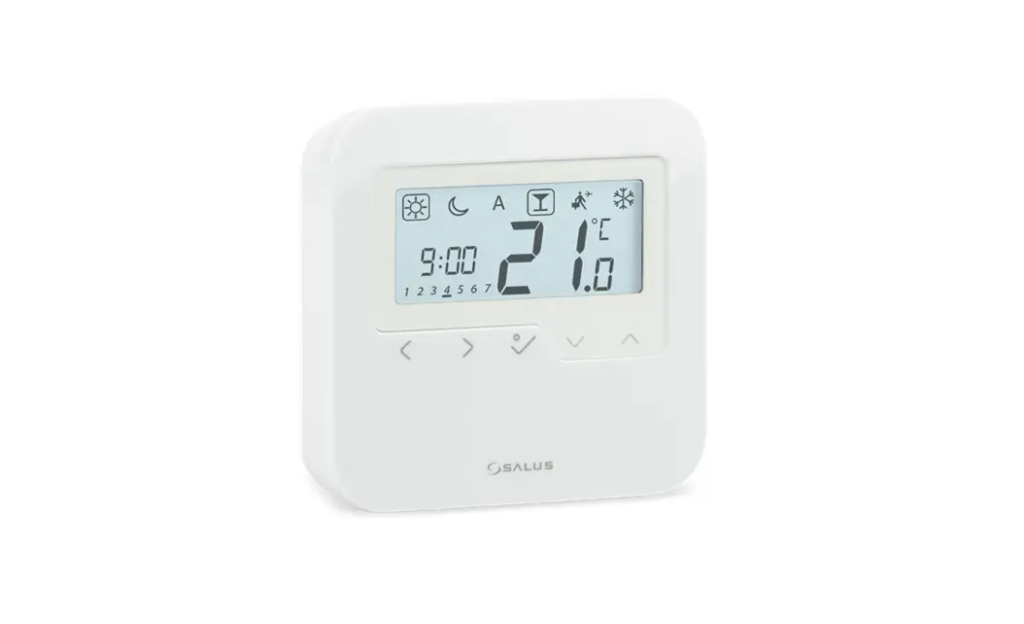
SALUS RT510SR Wireless Programmable thermostat Wiring Diagram

SALUS RT510SR Wireless Programmable thermostat Wiring diagram LEGEND Battery powered L, N 230V AC power supply Fuse COM, NO, NC Voltage free output S, S1, S2 Input terminals SL 230V AC voltage output Contact normally open Contact normally closed NC/COM/NO switch Boiler – Boiler connection * – Boiler’s contacts for ON/OFF thermostat (according to the […]
SALUS HTR24(20) wired Non-Programmable Thermostat Wiring Diagram

SALUS HTR24(20) wired Non-Programmable Thermostat Wiring diagram LEGEND Battery powered 230V AC power supply Fuse Voltage free output Input terminals 230V AC voltage output Contact normally open Contact normally closed NC/COM/NO switch Boiler – Boiler connection * – Boiler’s contacts for ON/OFF thermostat (according to the boiler’s instructions) Wireless communication Pump Valve actuator Temperature sensor […]
SALUS VS35 Wired digital Non-Programmable thermostat Wiring Daigram
SALUS VS35 Wired digital Non-Programmable thermostat Wiring diagram LEGEND Battery powered 230V AC power supply Fuse Voltage free output Input terminals 230V AC voltage output Contact normally open Contact normally closed NC/COM/NO switch Boiler – Boiler connection * – Boiler’s contacts for ON/OFF thermostat (according to the boiler’s instructions) Wireless communication Pump Valve actuator Temperature […]
SALUS VS30 Wired digital thermostat Wiring Diagram

SALUS VS30 Wired digital thermostat Wiring diagram LEGEND Battery powered 230V AC power supply Fuse Voltage free output Input terminals 230V AC voltage output Contact normally open Contact normally closed NC/COM/NO switch Boiler – Boiler connection * – Boiler’s contacts for ON/OFF thermostat (according to the boiler’s instructions) Wireless communication Pump Valve actuator Temperature sensor […]
SALUS RT510 Wired Programmable Thermostat Wiring Diagram

SALUS RT510 Wired Programmable Thermostat Wiring diagram LEGEND Battery powered 230V AC power supply Fuse Voltage free output Input terminals 230V AC voltage output Contact normally open Contact normally closed NC/COM/NO switch Boiler – Boiler connection * – Boiler’s contacts for ON/OFF thermostat (according to the boiler’s instructions) Wireless communication Pump Valve actuator Temperature sensor […]
SALUS RT310SPE Internet wireless Thermostat Wiring Diagram

SALUS RT310SPE Internet wireless Thermostat Wiring Diagram Wiring diagram LEGEND Battery powered 230V AC power supply Fuse Voltage free output Input terminals 230V AC voltage output Contact normally open Contact normally closed NC/COM/NO switch Boiler – Boiler connection * – Boiler’s contacts for ON/OFF thermostat (according to the boiler’s instructions) Wireless communication Pump Valve […]
SALUS RT310 Non-Programmable Thermostat Wiring Diagram
SALUS RT310 Non-Programmable Thermostat Wiring diagram LEGEND Battery powered 230V AC power supply Fuse Voltage free output Input terminals 230V AC voltage output Contact normally open Contact normally closed NC/COM/NO switch Boiler – Boiler connection * – Boiler’s contacts for ON/OFF thermostat (according to the boiler’s instructions) Wireless communication Pump Valve actuator Temperature sensor […]
SALUS HTRS-RF(30) Wireless Digital THERMOSTAT Wiring Daigram

SALUS HTRS-RF(30) Wireless Digital THERMOSTAT Wiring diagram LEGEND Battery powered 230V AC power supply Fuse Voltage free output Input terminals 230V AC voltage output Contact normally open Contact normally closed NC/COM/NO switch Boiler – Boiler connection * – Boiler’s contacts for ON/OFF thermostat (according to the boiler’s instructions) Wireless communication Pump Valve actuator Temperature sensor […]
SALUS HTRP230(50) Wired Digital THERMOSTAT Wiring Diagram
SALUS HTRP230(50) Wired Digital THERMOSTAT Wiring diagram LEGEND Battery powered 230V AC power supply Fuse Voltage free output Input terminals 230V AC voltage output Contact normally open Contact normally closed NC/COM/NO switch Boiler – Boiler connection * – Boiler’s contacts for ON/OFF thermostat (according to the boiler’s instructions) Wireless communication Pump Valve actuator Temperature sensor […]
SALUS BTRP230(20) Thermostat Wiring Daigram
SALUS BTRP230(20) Thermostat Wiring Daigram Wiring diagram LEGEND Battery powered L, N 230V AC power supply Fuse COM, NO, NC Voltage free output S, S1, S2 Input terminals SL 230V AC voltage output Contact normally open Contact normally closed NC/COM/NO switch Boiler – Boiler connection * – Boiler’s contacts for ON/OFF thermostat (according to the […]
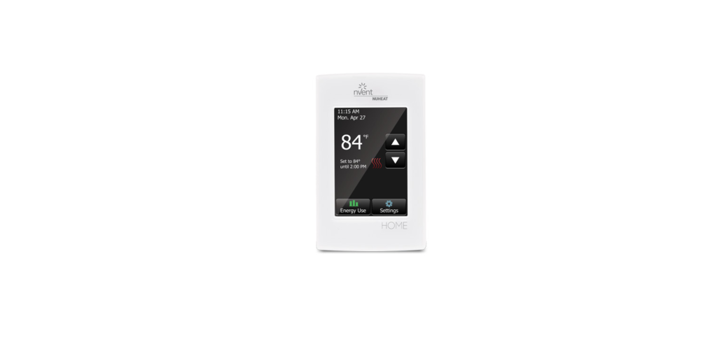
Nuheat Home Touchscreen Programmable Thermostat 240V Relay General Wiring Guide

Nuheat Home Touchscreen Programmable Thermostat 240V Relay General Wiring SIGNATURE, HOME, ELEMENT THERMOSTATS Terminals for the floor sensor are located on the FRONT side of the thermostat base (not illustrated). Wires of the floor sensor go into terminals C and D only (no polarity). nVent NUHEAT assumes no responsibility for field wiring. please consult […]
Nuheat Home Touchscreen Programmable Thermostat 120V Relay Wiring Guide
Nuheat Home Touchscreen Programmable Thermostat 120V Relay Wiring RELAY SWITCH OR CONTACTOR FOR 120V This switch allows you to control multiple circuits with a single control. It may be conveniently located inside an electrical junction box. EVENT NUHEAT FLOOR HEATING CONTROL WITH G.F.C.I. See the diagram for wiring instructions. WIRING INSTRUCTIONS FOR RELAY (120V) 0 […]
WarmlyYours nSpire Touch Wi-Fi Thermostat wiring Diagram Product Guide

WarmlyYours nSpire Touch Wi-Fi Thermostat Wiring Diagram Indoor Controls nSpire Touch WiFi Thermostat In addition to its WLAN network connection, this model features touchscreen operation, an easy-to-use Install Wizard, and easy access to a detailed log of its energy use. Its WiFi capability also means that a user can operate their heating system remotely. It […]
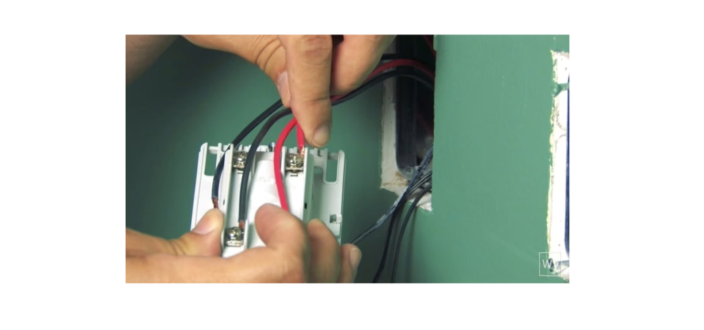
WarmlyYours nSpire Thermostat wiring Diagram Guide

WarmlyYours nSpire Thermostat Wiring WIRING DIAGRAM FOR 120V & 240V FLOOR HEATING SYSTEMS WITH NSPIRE SERIES THERMOSTATS USING A JUNCTION BOX FROM POWER SOURCES 120V & 240V ELECTRICAL ROUGH-IN Installation Support • (800) 875-5285 • www.WarmlyYours.com REFERENCE Download Manual WarmlyYours nSpire Thermostat wiring Diagram Guide WarmlyYours nSpire Thermostat Wiring Diagram Guide
WarmlyYours nSpiration Thermostat Tempzone Single wiring Diagram Guide

WarmlyYours nSpiration Thermostat Tempzone Single wiring For 120V & 240V Single Conductor TempZone with nSpire Touch Wi-Fi (UWG4), nSpire Touch (UDG4), nHance (UDG), nTrust (UTN4), nJoin (USG) ELECTRICAL ROUGH-IN FACEPLATE REMOVAL REAR OF THE BASE MAT HAS NO POLARITY RED OR YELLOW INDICATORS ON COLD LEAD INDICATE THE “BEGINNING” OF THE MAT. WHITE INDICATORS SIGNIFY […]
WarmlyYours nSpiration Thermostat Slab Heating wiring Diagram Guide
WarmlyYours nSpiration Thermostat Slab Heating wiring WIRING DIAGRAM For 120V & 240V Slab Heating Products with nSpire Touch Wi-Fi (UWG4), nSpire Touch (UDG4), nHance (UDG), nTrust (UTN4), nJoin (USG) MAT/CABLE HAS NO POLARITY DO NOT CUT THE HEATING WIRE ALWAYS TEST OHMS OF HEATING PRODUCT BEFORE, DURING, AND AFTER INSTALLATION ALWAYS TEST THE SENSOR AND […]
WarmlyYours nspiration Thermostat Environ Wiring Diagram Guide

WarmlyYours inspiration Thermostat Environ Wiring WIRING DIAGRAM For 120V & 240V Environ™ Heating Products with nSpire Touch Wi-Fi (UWG4), nSpire Touch (UDG4), nHance (UDG), nTrust (UTN4), nJoin (USG) ELECTRICAL ROUGH-IN FACEPLATE REMOVAL REAR OF THE BASE MAT HAS NO POLARITY COLD LEAD IS 15 FT (30 FT FOR EASY MATS) DO NOT SHORTEN THE MAT […]
EMERSON White Rodgers 1F81 Programmable Heat Pump Thermostat CONFIGURATION AND TYPICAL WIRING DIAGRAMS

EMERSON White Rodgers 1F81 Programmable Heat Pump Thermostat Configuration Menu Step 1F81-261 Press Button(s) 1F83-261 Press Button(s) Displayed (Factory Default) Press or to select: COMMENTS 1 PRGM and RUN N/A HOLD (0:00) 0 to 8 hrs (in 15 minute increments) Select temporary Hold time 2 HOLD* Set SYSTEM switch to OFF and Press and […]
Honeywell Home T4 Pro Thermostat Wiring Diagrams User Manual
Honeywell Home T4 Pro Thermostat Wiring Diagrams WIRING DIAGRAMS Stage Heat Only: Gas or Oil Furnace COMMON OPTIONAL. USED FOR INDEPENDENT FAN CONTROL ONLY. MOST HEAT-ONLY, GAS OR OIL-FORCED AIR SYSTEMS DO NOT USE A FAN WIRE. Stage Cool Only 1H/1C: Gas Furnace COMMON OPTIONAL. Transformer System, 1H/1C: Oil Furnace Transformer System, Hot […]
Drayton LWC1 Wiring Centre Wiring guide
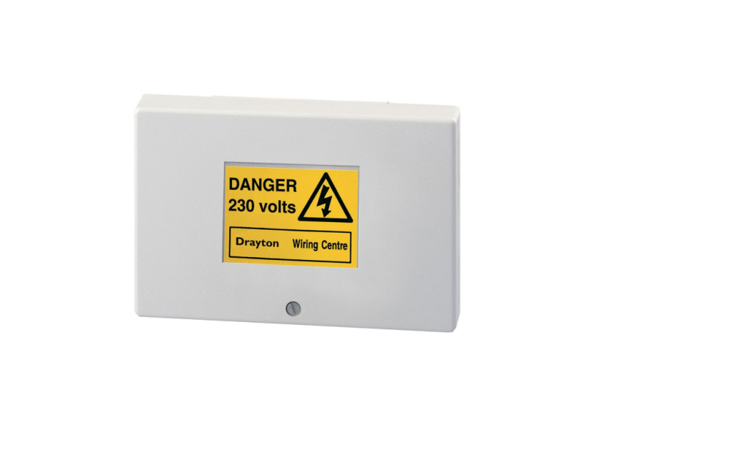
Drayton LWC1 Wiring Centre INTRODUCTION Wiring centres, designed to simplify wiring installations and circuit checking, lose some of their value if they are not in themselves easy to understand and use. The Drayton LWC1 wiring centre has been introduced to meet this requirement. The LWC1 is suited to all popular central heating and hot water […]
Vine 24V-AC Thermostat wiring Installation and User Manual

Vine 24V-AC Thermostat In the Box Wi-Fi Thermostat Two screws and anchors Flathead screwdriver Wire labels Jumper wire User manual Registration card Some features require an internet connection and a user account. Features, specifications, and appearance are subject to change without notice. Check Compatibility First For conventional (gas/oil/electric) and heat-pump systems 1-Heat & 1-Cool […]