Meitay-tec FMT-24-SUPER-PROG Programmable Thermostat Wiring Diagram
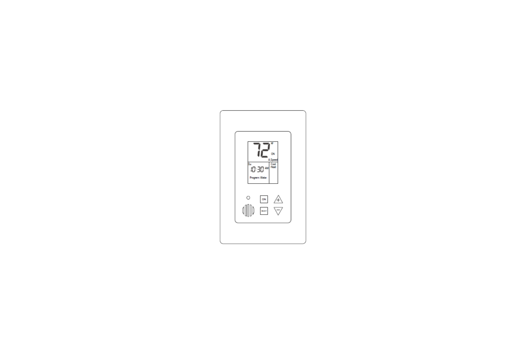
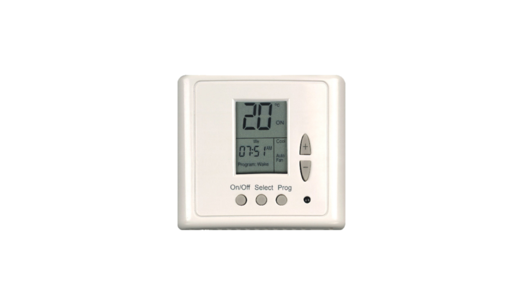
Meitay-tec FMT-24-SUPER-PROG Programmable Thermostat Technician Settings Temperature limits and Offset Press the ON button to turn the thermostat ON or OFF (The word “ON” or “OFF” will appear on display) Adjust the set-point temperature to 50oF. Press and hold the SELECT button (5 sec.) – “COOL” and the temperature limit for cooling will appear on […]
Meitay-tec ETN24-SUPER-3S-FP-PROG Programmable Thermostat Wiring Diagram
Meitay-tec ETN24-SUPER-3S-FP-PROG Programmable Thermostat WIRING DIP switch configuration Switch Internal / External sensor Heat-Cool / Heat Pump Heater type (HC only) Heat Pump conf. (HP only) 3 Minutes compressor delay Internal* External HC* HP Electric heat* Oil/Gas heat HP in cool* HP in heat With delay* Without delay 1 ON* OFF x x […]
Comfortheat MTC THERMOSTAT Wiring Diagram

Comfortheat MTC THERMOSTAT WIRING WIRING OF MTC THERMOSTAT WIRING OF MTC THERMOSTAT AND CONTACTOR CONTACTOR WIRING DETAILS ComfortHeat ComfortHeat Australia Pty Ltd 8/11 Ponderosa Parade Warriewood NSW 2102 p: 02 9979 8600 [email protected] REFERENCE: DOWNLOAD MANUALS: Comfortheat MTC THERMOSTAT Wiring Diagram OTHER MANUALS: Comfortheat MTC Electric & Hydronic Programmable Thermostat Operations Manual Comfortheat MTC THERMOSTAT […]
Comfortheat ETN THERMOSTAT Wiring Diagram
Comfortheat ETN THERMOSTAT WIRING WIRING OF ETN THERMOSTAT ETN & C-BUS CONTROL The ETN Thermostat is suitable for din type switchboard mounting. The connections to the thermostat are:- Terminal 1 & 2 Terminal 1~ 230V L Terminal 2 ~ 230V N Terminal 5 & 7 The heater load is normally connected directly to these terminals. […]
Comfortheat MCC2 THERMOSTAT Wiring Diagram

Comfortheat MCC2 THERMOSTAT WIRING WIRING OF MCC2/MCD2 THERMOSTAT WIRING OF MCC2/MCD2 THERMOSTAT AND CONTACTOR CONTACTOR WIRING DETAILS REFERENCE: DOWNLOAD MANUALS: Comfortheat MCC2 THERMOSTAT Wiring Diagram OTHER MANUALS: Comfortheat MCC2 Electric Programmable Thermostat Setup Manual Comfortheat MCC2 Hydronic Programmable Thermostat Operating Manual Comfortheat MCC2 Programmable Thermostat User Manual Comfortheat MCC2 THERMOSTAT Wiring Diagram
Comfortheat ETN4 THERMOSTAT Wiring Diagram
Comfortheat ETN4 THERMOSTAT WIRING OF ETN4 THERMOSTAT Heating load less than 3600W ETN Thermostats & C-Bus Control The ETN thermostat is suitable for din-type switchboard mounting. The connections to the thermostat are: Terminal 1 – 230V (L) Power Terminal 2 – Neutral (N) Terminal 3 – Temperature Setback – Output Terminal 6 – Temperature Setback […]
Comfortheat MTC2 THERMOSTAT Wiring Diagram

Comfortheat MTC2 THERMOSTAT WIRING OF MTD2 THERMOSTAT Heating load less than 3600W NOTE: The earth screen of all heating cables is to be connected to EARTH WIRING OF MTD2 THERMOSTAT AND CONTACTOR Where the floor heating load exceeds 3400W a contactor needs to be installed NOTE: The earth screen of all heating cables is to […]
Comfortheat MCD5 THERMOSTAT Wiring Diagram

Comfortheat MCD5 THERMOSTAT WIRING WIRING OF MCD5 THERMOSTAT WIRING OF MCD5 THERMOSTAT AND CONTACTOR CONTACTOR WIRING DETAILS ComfortHea ComfortHeat Australia Pty Ltd 8 11 Ponderosa Parade Warriewood NSW 2102 p: 02 9979 8600 [email protected] REFERENCE: DOWNLOAD MANUALS: Comfortheat MCD5 THERMOSTAT Wiring Diagram OTHER MANUALS: Comfortheat MCD5 ELECTRIC Programmable Thermostat Operating Manual Comfortheat MCD5 Hydronic Programmable […]
SALUS HTR230(20) Wired Non-Programmable Thermostat Wiring Diagram

SALUS HTR230(20) Wired Non-Programmable Thermostat Wiring diagram LEGEND Battery powered 230V AC power supply Fuse Voltage free output Input terminals 230V AC voltage output Contact normally open Contact normally closed NC/COM/NO switch Boiler – Boiler connection * – Boiler’s contacts for ON/OFF thermostat (according to the boiler’s instructions) Wireless communication Pump Valve actuator Temperature sensor […]
SALUS ERT2024V Non-Programmable Thermostat Wiring Diagram

SALUS ERT2024V Non-Programmable Thermostat Wiring diagram LEGEND Battery powered 230V AC power supply Fuse Voltage free output Input terminals 230V AC voltage output Contact normally open Contact normally closed NC/COM/NO switch Boiler – Boiler connection * – Boiler’s contacts for ON/OFF thermostat (according to the boiler’s instructions) Wireless communication Pump Valve actuator Temperature sensor 3-speed […]
SALUS BTR230(20) Non-Programmable Thermostat Wiring Diagram
SALUS BTR230(20) Non-Programmable Thermostat Wiring diagram LEGEND Battery powered 230V AC power supply Fuse Voltage free output Input terminals 230V AC voltage output Contact normally open Contact normally closed NC/COM/NO switch Boiler – Boiler connection * – Boiler’s contacts for ON/OFF thermostat (according to the boiler’s instructions) Wireless communication Pump Valve actuator Temperature sensor 3-speed […]
SALUS 091FLRFV2 Programmable Wireless Thermostat Wiring Diagram

SALUS 091FLRFV2 Programmable Wireless Thermostat Wiring diagram LEGEND Battery powered 230V AC power supply Fuse Voltage free output Input terminals 230V AC voltage output Contact normally open Contact normally closed NC/COM/NO switch Boiler – Boiler connection * – Boiler’s contacts for ON/OFF thermostat (according to the boiler’s instructions) Wireless communication Pump Valve actuator Temperature sensor […]
SALUS 091FLV2 Wired Programmable Thermostat Wiring Diagram

SALUS 091FLV2 Wired Programmable Thermostat Wiring diagram LEGEND Battery powered 230V AC power supply Fuse Voltage free output Input terminals 230V AC voltage output Contact normally open Contact normally closed NC/COM/NO switch Boiler – Boiler connection * – Boiler’s contacts for ON/OFF thermostat (according to the boiler’s instructions) Wireless communication Pump Valve actuator Temperature sensor […]
SALUS IT500 Internet Thermostat Wiring Diagram

SALUS IT500 Internet Thermostat Wiring diagram LEGEND Battery powered 230V AC power supply Fuse Voltage free output Input terminals 230V AC voltage output Contact normally open Contact normally closed NC/COM/NO switch Boiler – Boiler connection * – Boiler’s contacts for ON/OFF thermostat (according to the boiler’s instructions) Wireless communication Pump Valve actuator Temperature sensor 3-speed […]
SALUS VS20BRF Wireless Digital Thermostat Wiring Diagram

SALUS VS20BRF Wireless Digital Thermostat Wiring diagram LEGEND Battery powered 230V AC power supply Fuse Voltage free output Input terminals 230V AC voltage output Contact normally open Contact normally closed NC/COM/NO switch Boiler – Boiler connection * – Boiler’s contacts for ON/OFF thermostat (according to the boiler’s instructions) Wireless communication Pump Valve actuator Temperature sensor […]
SALUS RT520RF Wired Programmable Thermostat Wiring Diagram

SALUS RT520RF Wired Programmable Thermostat Wiring diagram LEGEND Battery powered L, N:230V AC power supply Fuse COM, NO, NC: Voltage-free output S, S1, S2:Input terminals SL:230V AC voltage output Contact normally open Contact normally closed NC/COM/NO switch Boiler – Boiler connection * – Boiler’s contacts for ON/OFF thermostat (according to the boiler’s instructions) Wireless communication Pump Valve […]
SALUS RT310SR Internet Wireless Thermostat Wiring Diagram

SALUS RT310SR Internet Wireless Thermostat DIMESION LEGEND Battery powered L, N:230V AC power supply Fuse COM, NO, NC:Voltage free output S, S1, S2:Input terminals SL:230V AC voltage output Contact normally open Contact normally closed NC/COM/NO switch Boiler – Boiler connection * – Boiler’s contacts for ON/OFF thermostat (according to the boiler’s instructions) Wireless communication Pump […]
SALUS RT310SPE Internet wireless Thermostat Wiring Diagram

SALUS RT310SPE Internet wireless Thermostat Wiring Diagram Wiring diagram LEGEND Battery powered 230V AC power supply Fuse Voltage free output Input terminals 230V AC voltage output Contact normally open Contact normally closed NC/COM/NO switch Boiler – Boiler connection * – Boiler’s contacts for ON/OFF thermostat (according to the boiler’s instructions) Wireless communication Pump Valve […]
SALUS HTRP230(50) Wired Digital THERMOSTAT Wiring Diagram

SALUS HTRP230(50) Wired Digital THERMOSTAT Wiring diagram LEGEND Battery powered 230V AC power supply Fuse Voltage free output Input terminals 230V AC voltage output Contact normally open Contact normally closed NC/COM/NO switch Boiler – Boiler connection * – Boiler’s contacts for ON/OFF thermostat (according to the boiler’s instructions) Wireless communication Pump Valve actuator Temperature sensor […]
SALUS HTRP-RF(50) Wireless Digital THERMOSTAT Wiring Diagram

SALUS HTRP-RF(50) Wireless Digital THERMOSTAT Introduction HTRP-RF(50) is a programmable wireless digital room thermostat compatible with devices that are part of the IT600 series, such as KL08RF wiring center, TRV10RFM thermostatic radiator valve and RX10RF boiler receiver. If you want the thermostat to control the devices via the Internet (Online Mode), please use the UGE600 […]
SALUS FC600 FAN COIL THERMOSTAT Wiring Diagram
SALUS FC600 FAN COIL THERMOSTAT Wiring diagram LEGEND Battery powered L, N:230V AC power supply Fuse COM, NO, NC: Voltage-free output S, S1, S2:Input terminals SL:230V AC voltage output Contact normally open Contact normally closed NC/COM/NO switch Boiler – Boiler connection * – Boiler’s contacts for ON/OFF thermostat (according to the boiler’s instructions) Wireless communication Pump Valve […]
SALUS EP310 Three-Channel Programmable Thermostat Wiring Diagram

SALUS EP310 Three-Channel Programmable Thermostat Wiring diagram LEGEND Battery powered L, N:230V AC power supply Fuse COM, NO, NC: Voltage-free output S, S1, S2:Input terminals SL:230V AC voltage output Contact normally open Contact normally closed NC/COM/NO switch Boiler – Boiler connection * – Boiler’s contacts for ON/OFF thermostat (according to the boiler’s instructions) Wireless communication Pump […]
SALUS RT310ISR Internet Wireless Thermostat Wiring Diagram

SALUS RT310ISR Internet Wireless Thermostat Wiring diagram LEGEND Battery powered L, N:230V AC power supply Fuse COM, NO, NC: Voltage-free output S, S1, S2:Input terminals SL:230V AC voltage output Contact normally open Contact normally closed NC/COM/NO switch Boiler – Boiler connection * – Boiler’s contacts for ON/OFF thermostat (according to the boiler’s instructions) Wireless communication […]
WarmlyYours nSpiration Thermostat Tempzone Twin wiring Diagram Guide

WarmlyYours nSpiration Thermostat Tempzone Twin Wiring Diagram WIRING DIAGRAM ELECTRICAL ROUGH-IN FACEPLATE REMOVAL MAT HAS NO POLARITY COLD LEAD IS 15 FEET DO NOT SHORTEN MAT DO NOT CUT THE HEATING WIRE ALWAYS TEST OHMS OF ROLE BEFORE, DURING AND AFTER INSTALLATION ALWAYS TEST THE SENSOR AND VERIFY 8˜15 K OHM RESISTANCE NEVER INSTALL ELECTRIC […]
WarmlyYours Hardwired Programmable Timer WIRING DIAGRAM

WarmlyYours Hardwired Programmable Timer ELECTRICAL ROUGH-IN ENSURE THE SYSTEM IS GROUNDED WE RECOMMEND TO ISOLATE THE YELLOW 3-WAY WIRE FROM THE OTHER WIRES USING A SOLDERLESS WIRE-NUT CONNECTOR. Installation Support (800) 875-5285 www.WarmlyYours.com References: Download Manual WarmlyYours Hardwired Programmable Timer WIRING DIAGRAM OTHER MANUAL WarmlyYours Hardwired Programmable Timer Installation and Operation Instructions WarmlyYours Hardwired Programmable […]