
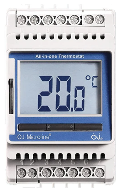
Comfortheat ETN THERMOSTAT
WIRING
WIRING OF ETN THERMOSTAT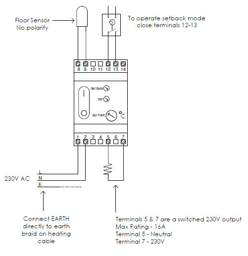
ETN & C-BUS CONTROL
The ETN Thermostat is suitable for din type switchboard mounting. The connections to the thermostat are:-
Terminal 1 & 2
- Terminal 1~ 230V L
- Terminal 2 ~ 230V N
Terminal 5 & 7
The heater load is normally connected directly to these terminals. Terminal 5 is the 230V Neutral and terminal 7 is the 230V Live. If the heater load is greater than 3600 Watts or 16A these terminals can be connected to the contactor coil to drive a contactor.
Terminal 8 & 9
Sensor input connections. These do not have a polarity.
Terminal 12, 13 & 14
These connections are used to drive the thermostat into setback mode. They are voltage-free contacts so when closed the setback mode operates. For single thermostat operation connect between 12 & 13. For multiple thermostat operations from the one timeclock connect the 1st thermostat across 12 & 13 and loop across to the rest between terminals 13 & 14.
C-Bus Control
To turn the floor heating On/Off (not daily control) the C-Bus can be used to switch the power supply to the ETN thermostat by breaking the 230V power supply to terminals 1 & 2. For daily control it is best to close terminals 12 &13 which will set the thermostat into ‘Setback Mode’ (i.e. a lower temperature). The C-Bus will be programmed for the ‘Setback Mode’ times.
Cable Extension
You can extend the sensor cable with a TWIN wire – Max Length 100m or similar.
WIRING OF ETN THERMOSTAT AND CONTACTOR
Where the floor heating load exceeds 3400W a contactor needs to be installed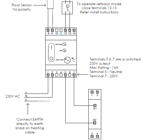
ETN & C-BUS CONTROL
The ETN Thermostat is suitable for din type switchboard mounting. The connections to the thermostat are:-
Terminal 1 & 2
Terminal 1~ 230V L / Terminal 2 ~ 230V N
Terminal 5 & 7
Switched 230V output. The heater load is normally connected directly to these terminals. Terminal 5 is the 230V Neutral and terminal 7 is the 230V Live. If the heater load is greater than 3600 Watts or 16A these terminals can be connected to the contactor coil to drive a contactor.
Terminal 8 & 9
Sensor input connections. These do not have a polarity.
Terminal 12, 13 & 14
These connections are used to drive the thermostat into setback mode. They are voltage free contacts so when closed the setback mode operates. For single thermostat operation connect between 12 & 13. For multiple thermostat operation from the one timeclock connect the 1st thermostat across 12 & 13 and loop across to the rest between terminals 13 & 14.
C-Bus Control
To turn the floor heating On/Off (not daily control) the C-Bus can be used to switch the power supply to the ETN thermostat by breaking the 230V power supply to terminals 1 & 2. For daily control it is best to close terminals 12 &13 which will set the thermostat into ‘Setback Mode’ (i.e. a lower temperature). The C-Bus will be programmed for the ‘Setback Mode’ times.
Cable Extension
You can extend the sensor cable with a TWIN wire – Max Length 100m or similar.
CONTACTOR WIRING DETAILS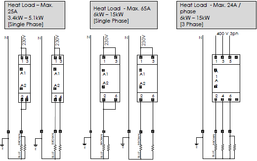
REFERENCE:
DOWNLOAD MANUALS:
Comfortheat ETN THERMOSTAT Wiring Diagram
OTHER MANUALS:
Comfortheat ETN Electric Programmable Thermostat Setup Manual
Comfortheat ETN Hydronic Programmable Thermostat Operating Manual
Comfortheat ETN Programmable Thermostat User Manual
![]()
Leave a Reply