
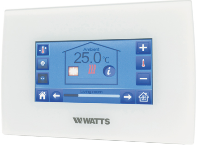
WATTS BT-CT02-RF Touchscreen Programmable Thermostat
GENERAL INFORMATION
Safety warnings and operating instructions
- This product should be installed preferably by a qualified professional. Subject to the observation of the above terms, the manufacturer shall assume the liability for the equipment as provided by legal stipulations. All instructions in this Installation & Operation manual should be observed when working with the controller.
- Failures due to improper installation, improper use or poor maintenance are voiding manufacturer liability
- Any attempt to repair voids the responsibility and the obligation to guarantee and replacement from the manufacturer.

Disposal and recycling information
The full text of the EU declaration of conformity is available at the following internet address: www.wattswater.eu
- 2012/19/EU (WEEE directive): Products marked with this symbol cannot be disposed of as unsorted municipal waste in the European Union. For proper recycling, return this product to your local supplier upon the purchase of equivalent new equipment, or dispose of it at designated collection points. For more information see: www.recyclethis.info
- 2006/66/EC (battery directive): This products contains a battery that cannot be disposed of as unsorted municipal waste in the European Union. See the product documentation for specific battery information. The battery is marked with this symbol, which may include lettering to indicate cadmium (Cd), lead (Pb), or mercury (Hg). For proper recycling, return the battery to your supplier or to a designated collection point. For more information see: www.recyclethis.info
PRESENTATION
Thank you for choosing WATTS Vision®, a Wireless communication system for controlling heating and cooling system. It allows multi zones management (up to 50) of your electrical and hydraulic heating system.
The central unit, main characteristics:
- Touch screen
- Interface via internet (WiFi)
- Wall mountable with power supply 85-265VAC (50-60) Hz
- Table mountable with supplied bracket and mini USB power supply (0-5V) (sold separately)
- Back up Battery for installation operation of 1 hour maximum
- RF Communication only with WATTS Vision® devices (up to 40m internal, extendable with repeater)
- Able to manage up to 50 zones or rooms and 4 main supply circuits with a dedicated pump or boiler on each
- Multiple heating / cooling devices control
- SD Card slot for updating software
- Intuitive menus for devices management
Content of the packaging:
- central unit
- 230V Flush mounted power supply
- wall/table support
- CE conformity declaration
- Installation and user guide
INSTALLATION
Installation sequence
Please follow the set-up sequence below;
- STEP 1: Install your central unit (see 2.2 Install your central)
- STEP 2: Create your house / create and name your rooms (see 3.3 Configure your house). Please note when pairing the BT-M6Z02 RF with the central unit, the rooms are automatically created according to the number of RF thermostats.
- STEP 3: Pair your devices to the central controller / allocate them to the appropriate rooms (see 3.4 Pair your devices to the central) Please charge the central unit for at least 1 hour before pairing the devices already mounted
- STEP 4: Personalise your central unit user settings (see 3. Settings)
- STEP 5: Set up Wifi for remote control of your system via smart-phone / tablet (see 6. Set up Wifi control )
- STEP 6: Program your devices so that they work on a time schedule (see 7. Heating)
Install your central
Wall mounting
Table installation (with optional mini USB cable – sold separately)

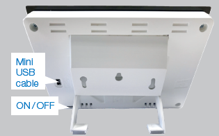
- Connect the central unit with the mini USB cable (5V, 1A) and then mount the leg support on it and put the switch on ON position. The central unit is ready for operation.
Main screen icons description
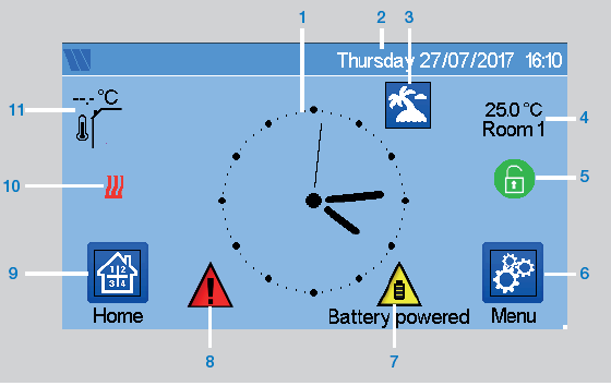
- Display the time or the ambient T° of the room or zone. Make your choice by pressing on the central part of the screen
- Date
- Holidays mode status.
- Display the ambient temperature in desired room.
- Screen lock. Long press toggles between locking / unlocking.
- Main menu.
- The device is working on battery (! only for settings and pairing).
- Error flag – press to access RF, limits, alarms, battery anomalies.
- Rooms access (if Central is locked – cannot change settings).
- Boiler status displayed if connected to the Central.
- Outside sensor temperature (Require Outdoor sensor device)
General pictograms and actions
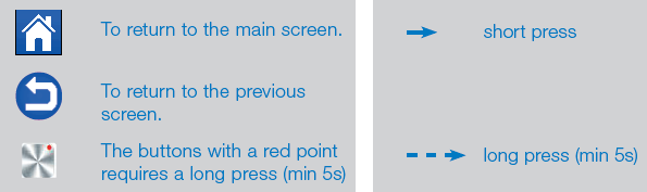
SETTINGS
Main menu
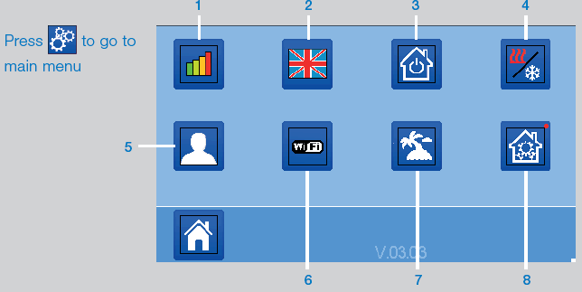
- Energy consumption statistics menu.
- Language (the flag of the current language is displayed). 8 languages are proposed. If you want to select another language, you need to insert the software (available on www.wattswater.eu.) on a microSD then select yours.
- General commands menu. Use this menu to put all the same devices type in the same operating mode.
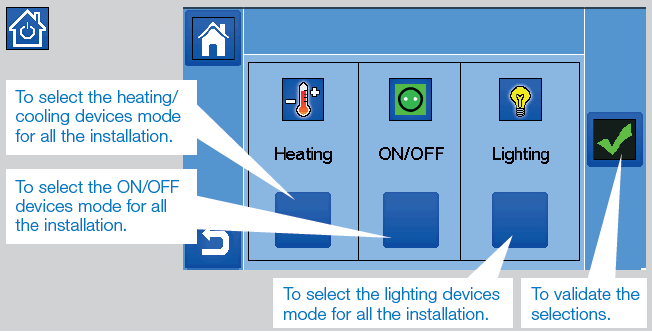
 Heating/cooling mode management menu. See section “Heating and cooling control”
 User settings menu.
In this menu, you can set:-
- Time, Date (Manual, Automatic).
- Time zone (UTC) if the device is in automatic time update mode.
- Time and date if the device is in manual time update mode.
- Summer-Winter (Manual, Automatic).
- Temperature unit (°C, °F).
- Background Color.
- Buttons color.
- Backlight.
- Screen saver (Enabled, Disabled).
- Default screen (Home, Clock, Disabled)
- Screen cleaner.
- Factory default user (interface).
-
 WIFI menu.
 Reading button (refreshment).
- The Internet Access password allows to link your central unit to your Internet account (See below) for a remote control of your system through the Internet or Smart Phone. n.b.: At first use or software update, wait for some time until the green State icon is active.
 Holidays menu.
- To set the departure / return dates and time.
- Use < or > to select year / month / day, hour & minute.
- Set and validate the operating mode of the devices in holiday mode. (Same menu then general commands menu).
 Installation menu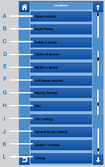
- A House creation.
- See house creation section.
- B Radio pairing.
- See radio pairing section.
- C Delete a device:
- Select device type and then the device.
- D Delete all devices:
- All devices installed in the system will be deleted (rooms will be maintained).
- E Identify a device
- To identify a device of the installation, go to Installation Menu, then “Identify a Device”
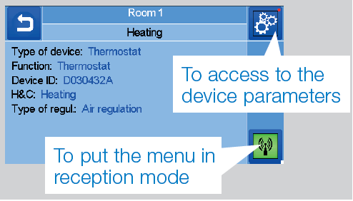
- Process:
 to make the Central listening on the device receiver and wait a few seconds until radio communication frame is transmitted.
- Note: ID-number is displayed on the screen, please repeat to be sure to have the same ID.
 to change device parameters (name, power …).
- To identify a device of the installation, go to Installation Menu, then “Identify a Device”
- F Antifreeze setpoint:
- You can set the antifreeze setpoint as reference for the whole installation.
- G Heating setting:
- You can fix setpoint limitations (min/ max) per zone and the offset assigned to devices working in floor sensor regulation
- H Heating/cooling settings:
- You can set the installation:
- in heating mode,
- in cooling mode or
- in manual mode.
- If you set the device in manual mode, the icon appears on the main menu.
- You can set the installation:
- I WIFI settings:
- To set the WIFI configurations (SSID/ Protected Access Key Type/ Password). You can do it manually or scan the active networks.
- Configuration requesting a registration on a web page is not supported.
- WIFI Status:
- 0/2: Central unit not connected to the wifi router and server
- 1/2: Central unit connected to the Wifi router (not to the server)
- 2/2: Central unit connected to the wifi router and to the server (Pairing of the central to an account is required)
- n.b.: The connection to Internet is recommended with Certified WiFi routers (http://www.wi-fi.org/certification).
- n.b.: Automatic pairing time to WiFi router with WEP key: 3-4 min, with WPA2 key: 1 min. n.b.: For the network scan, Repeat at least twice the operation if your desired WiFi network is not displayed. If your desired WiFi network is still not displayed, enter the WiFi settings manually
- J General factory default:
- To reset the system with the factory values, but the software version will remain the same.
- K Update Firmware:
- To update the software, with the SD-card. The system is qualified to work with SD-cards less than or equal to 16GB. Please wait the end of the update procedure (The Wifi icon should be available for the Wifi central unit) before removing the microSD from the central unit. The SW and the procedure to update the central unit is available on www.wattswater.eu.
- L Cloning:
- The menu allows to transfert a configuration from central 1 to central 2. If you change the central, you do not have to reconfigure your system. Put update.bin file on SD card (Special software for cloning available on www.wattswater.eu). Insert the SD card (load with the cloning sofware) in central 1 and make an update firmware. Insert the same SD card in central 2 and launch the cloning. After the cloning, you need to reconfigure the Wifi and the language.
- A House creation.
Adjust time/user settings
 Language
 Set the time and the date manualy or in automatically you have to set the time zone (UTC) and the device is getting the time from internet (WIFI connection is needed). Personalise your screen settings, e.g. background colour etc. See “User Settings Menu” in MAIN MENU section for further information.
Configure your house

Create all the rooms and re-name them e.g.:
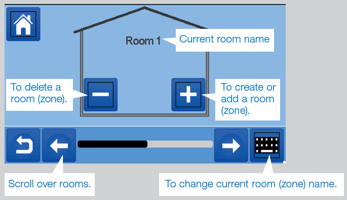
- room 1 = Kitchen,
- room 2 = Lounge etc,
where the various devices such as thermostats will be placed.
Pair your devices to the central
- Install your devices (see relevant device manuals)
- Create the room if it doesn’t exist (See section 3)
- Go to Radio pairing

- Choose the device type (heating, On/Off Device etc)
- Choose the room
- Note: The master (thermostat or BT-M6Z02 RF) must be the first paired device
- Put the device in pairing mode (refer to device leaflet)

- Follow the instructions given by the Central (check on the device that the pairing is successful, refer to the device leaflet)
- n.b.: Automatic pairing time in case of RF communication loss: 10s.
- n.b.: Pairing of the repeater: Select any device type, any room and does not consider the pairing failure message on the central unit at the end of the procedure. The led should be green fix on the repater.
- Check the successful installation
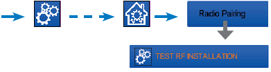
- You will have a warning
 in home menu for RF errors communications. The warning flag should appear for a maximum of 10mn. It would then disappear if there are no communication problems. If not, check devices showing RF errors, try moving them to another place and repeat the procedure.
- You will have a warning
HYDRAULIC SYSTEM ASSIGNEMENT
Within an installation, it may be necessary to control devices such as pumps, valve drives or heat / cool producers, as soon as heating or cooling demand exists on at least one zone. With WATTS Vision®, up to 4 such devices can be switched via the “hydraulic circuit” function. Each of these 4 possible circuits can be controlled via a single radio receiver.
- STEP 1: Define which device is assigned to a hydraulic circuit With the plan of your installation, define which devices are on “circuit 1”. Then, using the Central controller, pair and configure all these devices on circuit 1.
 enter a zone (room) that belong to circuit 1,
 , and select one device of circuit 1 (radio connecting box, radio receiver or radiator thermostatic head)
 Now you have entered the configuration menu of the device. Select the menu “Heating settings” and make sure that “Hydraulic heating” is selected
- You can now select the hydraulic circuit linked to this receiver (e.g. circuit 1).
 Repeat the procedure for each device of the room (zone) you want to link to the hydraulic circuit. Further devices can be selected using the buttons [<<<] or [>>>] at the top of the device name. Repeat the procedure for each room (zone) that you want to link to hydraulic circuit 1. If you have assigned all rooms / devices, repeat the procedure for any further hydraulic circuits.
- STEP 2: pairing radio receiver hydraulic circuit with the central unit
- For each circuit, you can link a circuit receiver to drive the pump devices, valve drive or heat / cool generator of the circuit. This can be done for example by BT-WR02 RF.
- Select “Circuit”, then select the number of the circuit, e.g. circuit 1. Put the radio receiver in pairing mode (BT WR02 RF).
- Repeat the procedure for additional hydraulic circuits.
Heat and Cool installations
If your installation includes both heating and cooling functions, you can switch either from Heat to Cool manually or automatically:
- If you have a BT HCM02 RF in your installation set as “Master” (refer to Manual instruction of the device) then all is automatic you don’t have to do anything
- For all other cases, you have to do the switch manually:
 and go in “H&C”. There you will have the choice netween “Heating Only” “Cooling Only” or “Manual Reversible”. With this last option, you create a shortcut in the main menu where you can easily change Heat/Cool mode
 .
.
Notes
- In Cooling Mode, Reduced mode and Antifreeze mode are inactive:
- icon
 is displayed
 - instead of
 .
.
- icon
- In the thermostat, user can configure the parameter “Cold” that allows the zone to do Cooling or not. If it is set to “No”, then if the mode of the zone is Cooling then the zone won’t make Cooling.
INSTALLATION TYPES (HEATING / COOLING)
TYPE 1 In this configuration:

- Pair first the thermostat (master) with the Central before pairing the other devices (configured as heating devices).
- The actuators regulate on thermostat temperature.
TYPE 2 In this configuration:
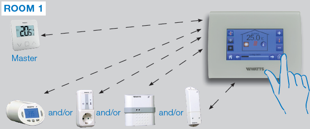
- Pair first the thermostat (master – configured as a heating device) with the Central before pairing the other devices.
- The other devices regulate on thermostat temperature.
Warning: In this installation type, the thermostat (MASTER) must be in regulation Air mode (not floor or Air + Floor)
TYPE 3 In this configuration (no thermostat)

- BT-TH configured as heating device. BT-PR, BT-FR, BT-WR can be configured as an On / Off or lighting devices.
TYPE 4 In this configuration
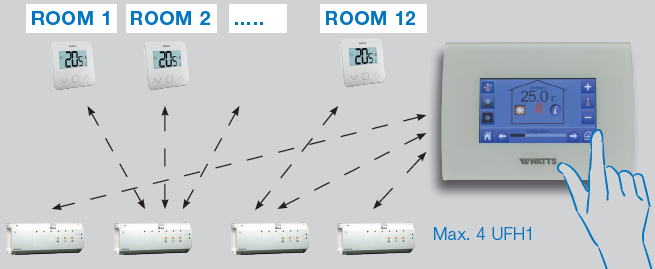
- Each thermostat is first paired with the appropriate UFH1 and then the UFH1(s) are paired with the Central
- During the pairing, the Central automatically creates rooms according to the number of thermostats (rooms) of UFHs.
SET UP WIFI
CONNECTION FOR MOBIL APP REMOTE CONTROL
- STEP 1: Connect the central unit to your WiFi network:
- Choose WiFi settings
- Choose Research Networks (searches for your wifi)
- Choose your WiFi from the list and enter your regular WiFi password
- Observe unit counting down from 120 to zero
- Make sure that the central is now connected to the WiFi network with an IP address (WiFi status should read 1/2)

- If after several attempts, connection is unsuccessful, connect the central unit to WiFi manually (see WiFi settings)
- STEP 2: Download the app to your device:
- For PC: click on dedicated link available on www.wattswater.eu homepage
- For Smartphone: download WATTS Vision® application from App store or Google Play.
- STEP 3: Create an Account
- Enter your details and select language.
- Select “Validate” (email will be sent to you with link).
- Go to your email and click on the link.
- Go back to your App account and follow the on screen instructions.
- Request a pairing code to link your central unit. The pairing code (valid 24h) is sent to your email inbox.
In the WiFi status menu  of the central unit, enter the pairing code (internet access password). Your central unit should appear after a few minutes in the application or the web page. Click the refresh button if necessary. WiFi status should read 2/2.
Please note: It may take up to a few hours to display all rooms and devices in the application. You can then operate your central unit from anywhere. Watts is not responsible for the correct operation of the connected devices, and potential damage caused by the malfunction or improper use of the connected devices and appliances.
HEATING/COOLING DEVICES MANAGEMENT & PROGRAMMING
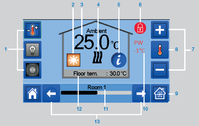
in the main screen and after selecting the room
- Device type choice (heating/cooling, lighting, On/Off). These buttons are only displayed if one device type is installed in the room (colored if active).
- Current mode, press on this icon to enter in the menu where you can change the current operating mode.
- Ambient temperature or setting temperature (setpoint) or humidity after one press on 8.
- Heating/cooling indicator (animated if demand).
- Information about the heating/cooling devices installed in the room
- Only displayed if the screen is locked.
- Set the current setpoint (deactivated if the screen is locked).
- To display either the ambient or setting temperature or Humidity in 3.
- Quick access to the desired room.
- Pilot wire status.
- Current room name.
- Floor temperature if floor regulation.
- Room changing.
 to access this modes menu:
MODES
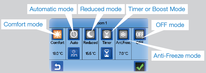
- Comfort Mode: Set the room in comfort mode. If it remains active, the comfort temperature will be followed all the time.
 Reduced Mode: Set the room in reduced mode. If it remains active, the reduced temperature will be followed all the time.
 Timer or Boost Mode: Temporary derogation. Set the timer duration (days, hours, minutes) by pressing on
  button, then validate and set the desired temperature on main screen.
 Anti-freeze Mode: Use this mode to put your room in anti-freeze mode (the temperature is set in the Installation menu)
 OFF Mode: To switch OFF the device (room in off mode). Be careful! In this mode, your installation can freeze!
Programming your devices
- Auto Mode: In this mode, the room temperature will follow the program you have chosen. You can choose between existing programs or you can create a new one that you can modify as you want.
 to select between: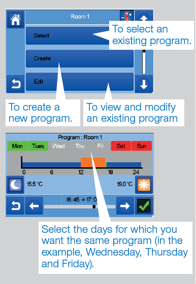
- Use the Comfort button
 to select the hourly ranges during which the comfort temperature will be followed (brown range)
- and the reduced button
 to select the hourly ranges during which the reduced temperature will be followed (blue range).
 - Use the arrows
 and
and  to put the cursor on the desired hours.
- and the reduced button
- Use the Comfort button
Validate the program; the validated days are then highlighted in green (on this example: Monday and Tuesday). The days that are not programmed are displayed in red.
Information
- to view the current program
- Default programms:
- P1: morning, evening & weekend.
- P2: morning, midday, evening & weekend.
- P3: day & weekend.
- P4: evening & weekend.
- P5: morning, evening (bathroom).
Lighting devices management
in the main screen and

- Device type choice (heating / cooling, lighting, On / Off). These buttons are only displayed if one device type is installed in the room (colored if active).
- Information about the lighting devices installed in the room.
- Indicates both the current lighting device number / the number of lighting devices in the room.
- Only displayed if the number of devices is upper than 1; used to select the devices in the room.
- Only displayed if the screen is locked.
- Quick access to the desired room.
- General management for all lighting in the room.
- Current room.
- Room changing.
- Indicates the lighting status. A press on it switches the lighting status.
Please note that the lighting functionality does not support programs. If you want to program the lighting devices, please set the devices as ON / OFF.
ON/OFF devices management
in the main screen and on

- Long press to switch between auto mode and normal mode (colored if active).
- Information about the device.
- Indicates both the number of the current device / number of devices in the room.
- Displayed only if the device is in Auto mode, press to access and edit the device program.
- Only displayed if the number of devices is upper than 1; used to select the devices in the room.
- Only displayed if the screen is locked.
- General management for all the ON / OFF devices in the room.
- Quick access to the desired room.
- Current room.
- Room changing.
- Indicates the ON / OFF status. A press on it switches the status of the device.
- Device type choice (heating/cooling, lighting, On / Off). These buttons are only displayed if one device type is installed in the room (colored if active).
MAINTENANCE
Cleaning of the central unit
Gently dust the outside of the central with a soft, lint-free cloth. If the central needs a more thorough cleaning:
- Lightly dampen a soft and clean cloth with water.
- FAQ, trouble shooting and software updates of the central unit
- Please visit our website wattswater.eu in section “WATTS Vision® Smart Home System”
- Wring out any excess water from the cloth.
- Gently wipe the display and sides of the central, making sure no drops of water accumulate around the product.
TECHNICAL CHARACTERISTICS
It is an electronic control device
| Operating temperature, connected. Operating temperature, battery Shipping and storage temperature | -30°C to +40*C 0°C to +40°C
-30°C to +50°C |
| Electrical Protection Electrical insulation | IP30
Class II |
| Temperature precision | 0.1°C (from thermostat) |
Setting Temperature Range
|
5°C to 30°C in 0.5°C steps 5°C to 30°C in 0.5°C steps 5°C to 10°C |
| Power Supply | 85-265V, 50-60 Hz |
| Radio Frequency | 868 MHz, <10mW, Range <40m internal, <100m open space |
| Software version | User interface: Shown on the main menu V.xx.xx Wifi communication: Shown on the wifi menu xx.xx |
| SD card | <=16GB (FAT) |
| WIFI | 802.11b – 2.4GHz
802.11g – 2.4GHz |
| Dimensions | Width: 158 mm, Height: 116,50 mm, Depth: 20,5 mm |
| Weight (Central unit + power supply + table support) | 0.635kg |
EU Declaration of Conformity
Hereby, Watts Electronics declares that the radio equipment is in compliance with the relevant Community harmonisation legislation:
| Designation | Description | Link |
| Low Voltage Directive (LVD) | The Low Voltage Directive (LVD) (2014/35/EU) | 2014/35/UE |
| 2014/35/EU | ensures that electrical equipment within certain | |
| voltage limits provides a high level of protection | ||
| for European citizens, and benefits fully from the | ||
| Single Market. | ||
| Electromagnetic | The Electromagnetic Compatibility (EMC) Directive | 2014/30/UE |
| Compatibility (EMC) | 2014/30/EU ensures that electrical and electronic | |
| Directive 2014/30/EU | equipment does not generate, or is not affected by, | |
| electromagnetic disturbance. | ||
| Radio Equipment
Directive (RED) 2014/53/EU |
The Radio Equipment Directive 2014/53/EU (RED) establishes a regulatory framework for placing radio equipment on the market. | 2014/53/EU |
| Restriction of the use of cer- tain hazardous substances Directive (RoHS) 2011/65/ EU | Directive on the restriction of the use of certain hazardous substances in electrical and electronic equipment. | 2011/65/EU |
| Waste Electrical
& Electronic Equipment Directive (WEEE) |
The WEEE Directive (2012/19/EU) aims to reduce the amount of waste electrical and electronic equipment that ends up in landfill. | 2012/19/EU |
| Ecodesign Commission Regulation (EU) 2015/1188 | Ecodesign requirements for local space heaters. | 2015/1188 |
| Directive 2001/95/EC on General Products Safety | Ensure that only safe products are sold on the market | 2001/95/EC |
COMPATIBLE DEVICES
 |
Hydraulic panel heater | Electrical panel heater (P) Electrical Floor (F) | Heating(H)/Cooling(C) | Hydraulic floor regulation | On/Off Switch |
| BT-A02 RF Wireless Thermostats BT-D02 RF
BT-DP02 RF BT-D03 RF |
√ | P F | HC | √ | |
| BT-TH02 RF Electronic thermostatic head for hydraulic radiator | √ | H | |||
| BT-FR02 RF Flush mounted receiver. Live contact 16A | P F | HC | √ | √ | |
| BT-WR02 RF Wall mounted receiver. Live contact 10A | P | HC | √ | √ | |
| BT-WR02 HC RF Wall mounted receiver. 2 free contact relays 5A | HC | √ | |||
| BT-WR02 FC RF Wall mounted receiver. Free contact 10A | P | HC | √ | √ | |
| BT-PR02 RF EU Plug for driving electrincal heater or electrical
device. Live contact 16A 230VAC |
P | HC | √ | ||
| BT-M6Z02 RF Master 6 zones for hydraulic under floor heating
and cooling |
HC | √ | |||
| BT-HCM02 RF * Heating and cooling under floor management | HC | √ | |||
| REPEATER RF extension range |
- BT-M6Z02 RF is mandatory
Maximum devices/limitations
- 50 rooms/zones heating / cooling master devices (thermostats) and 50 heating / cooling slave devices (receivers).
- 25 ON / OFF devices with weekly program with 15 min steps.
- 50 lighting devices (ON / OFF).
- You may have to use a Watts RF repeater if you want to extend the RF range.
CONTACTS
United Kingdom
- Watts Industries UK Ltd
- Colmworth Business Park
- Eaton Socon St. Neots
- PE19 8YX United Kingdom
- T: +44 (0) 1480 407074
- F: +44 (0) 1480 407076
- Email: [email protected]
- http://wattswater.co.uk
Germany, Austria and Switzerland
- Watts Industries Deutschland GmbH
- Godramsteiner Hauptstr. 167 76829 Landau Germany
- T: +49 (0) 6341 9656 0
- F: +49 (0) 6341 9656 560
- Email: [email protected]
- http://wattswater.de
Italy
- Watts Industries Italia S.r.l.
- Via Brenno, 21 20853 Biassono (MB)
- T: +39 039 4986.1
- F: +39 039 4986.222
- Email: [email protected]
- http://wattswater.it
Spain
- Watts Ind. Ibérica, S.A.
- Pol. Ind. La Llana – Av. La Llana, 85 08191 Rubí (Barcelona) Spain
- T: +34 902 431 074
- F: +34 902 431 075
- E-mail: [email protected]
- http://wattswater.eu
Denmark, Sweden, Norway and Finland
- Watts Industries Nordic AB
- Godthåbsvej 83 DK-8660 Skanderborg
- T: +45 86520032
- F: +45 86520034
- E-mail: [email protected]
- http://wattswater.eu
Poland
- Watts Industries Polska sp.z o.o.
- Puławska 40A 05-500 Piaseczno
- T: + 48 22 702 68 60
- F: + 48 22 702 68 61
- Email: [email protected]
- http://wattswater.pl
Russia
The descriptions and photographs contained in this product specification sheet are supplied by way of information only and are not binding. Watts Industries reserves the right to carry out any technical and design improvements to its products without prior notice.” Warranty: All sales and contracts for sale are expressly conditioned on the buyer’s assent to Watts terms and conditions found on its website at www.wattsindustries.com Watts hereby objects to any term, different from or additional to Watts terms, contained in any buyer communication in any form unless agreed to in a writing signed by an officer of Watts.
CONTACT
Watts Electronics S.A.S
- B.P. N°10 – Z.A. des Tourettes, 43800 ROSIERES, France
- T: +33(0) 471 57 40 49,
- F: +33(0) 471 57 40 90,
- www.wattsindustries.com
- www.wattswater.eu
PPLIMW15428C
© 2019 / 06 Watts
Reference
DOWNLOAD MANUAL:
WATTS BT-CT02-RF Touchscreen Programmable Thermostat INSTALLATION INSTRUCTIONS
OTHER MANUALS:
WATTS BT-CT02-RF Touchscreen Thermostat Technical Data Sheet

WATTS BT-CT02-RF Touchscreen Programmable Thermostat INSTALLATION INSTRUCTIONS