
SIEMENS RDD310/EH Flush-mount Room Thermostat

Key features
Key features of both types of thermostats:
- Operating voltage AC 230 V
- 2-position control with On/Off control output
- Maximum load 16 A
- Protection class IP31, suitable for installation in wet rooms
- Input for cable temperature sensor NTC 3 k (QAP1030/UFH) for the floor (note: cable temperature sensor must be ordered separately)
- Floor temperature limitation with cable temperature sensor
- Operating modes: Comfort, Economy and Frost Protection
- Minimum and maximum limitation of setpoint setting range
- Backlit white LCD
- Suitable for use with standard conduit boxes in Europe (CEE/VDE) and Asia-Pacific (min. depth 40 mm)
Additional feature of RDE410/EH:
- Auto Timer with 8 programmable time switches
Use
RDD310/EH and RDE410/EH room thermostats are used to control the room temperature in…
- single-family and holiday houses,
- multi-family houses with individual heating systems.
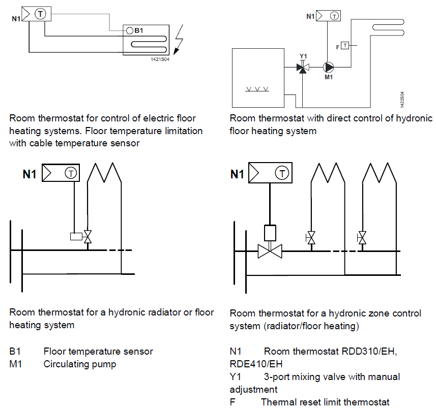
For control of the following pieces of equipment: - Specifically for electric floor heating systems, but also for…
- thermal valves or zone valves,
- gas or oil burners (boilers) (an additional relay must be used to connect a potential-free contact),
- pumps,
- radiators or connectors.
Functions
- Room temperature control in connection with built-in or external sensor
- Selection of operating mode via the operating mode button on the thermostat
- Display of current room temperature or setpoint in C
- The minimum and maximum limitation of setpoint setting range
- Button lock (automatic or manually)
- Floor temperature limitation with cable temperature sensor
- Backlit white LCD
- Reloading factory settings for commissioning and control parameters
- Auto Timer: 8 programmable 7-day time switches to switch between Comfort and Economy mode (RDE410/EH only)
Temperature control
The thermostat acquires the room temperature with its built-in sensor and maintains the setpoint by delivering control commands. The switching differential is 1 K.
Function diagram
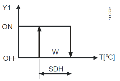
- T: Room temperature
- SDH Switching differential heating
- W: Room temperature setpoint
- Y1: Output signal for heating
Floor heating application
- The factory setting for this function is “Off” and must be set to “On” if floor heating is used. This function is activated via parameter P38.
- The installer must select the capacity of the heating system (in kW) via parameter P45 during commissioning.
- The cable temperature sensor is connected to input X1, M and acquires the floor temperature. If the floor temperature exceeds the parameterized limit xx ºC (P38 = 1, P51 = xx ºC), the heating system is turned off until the floor temperature returns to a level below the parameterized limit. Typical applications are rooms (dry floor).
- If the application does not require floor temperature limitation but instead uses the external sensor for room temperature display and control, the parameters will have to be set as follows: P38 = 1, P51 = Off. Typical applications are bathrooms (wet floor) where a constant floor temperature is required.
- It is not recommended to have only a built-in room sensor for floor heating since in that case there is a potential risk of overheating.
Operating modes
The operating mode is selected via the operating mode button ![]() . The respective setpoint maintains the room temperature at the desired level. The following operating modes are available:
. The respective setpoint maintains the room temperature at the desired level. The following operating modes are available:
- Comfort mode

In Comfort mode, the thermostat maintains the setpoint which can be adjusted via the +/– buttons. - Economy mode

Economy mode helps save energy. It is selected via operating mode button if parameter P02 is set accordingly.
 - Frost Protection mode
In Frost Protection mode, the system is protected against frost (factory setting = 8 °C). - Auto Timer mode
 AUTO (only with RDE410/EH)
In Auto Timer modeAUTO, the thermostat switches automatically between Comfort and Economy mode according to the 8 programmed time switches. The display shows Auto Timer mode symbol AUTO along with the symbol for the current operating mode (Comfort or Economy).
Setpoints
- Comfort mode
The Comfort setpoint is adjusted with the +/– buttons. Factory setting for the Comfort basic setpoint is 20 °C, which can be changed via parameter P08. The Comfort basic setpoint is used in conjunction with the “Temporary setpoint” function. - Setpoint limitation
The setpoint setting range can be limited to a minimum (parameter P09) and maximum (parameter P10). - Temporary setpoint
If “Temporary setpoint” is enabled via parameter P69, the setpoint adjusted via the +/– buttons is set back to the Comfort basic setpoint (parameter P08) when the operating mode changes. - Economy mode
Control parameter P11 is used to adjust the Economy setpoint (factory setting = 16 °C). - Frost Protection mode

Control parameter P65 is used to adjust the setpoint for Frost Protection mode (factory setting = 8 °C). - Caution

If a setpoint is set to “Off”, the thermostat does not maintain the setpoint in the respective operating mode, which means no protective heating function, resulting in risk of frost.
Type summary
| Product no. (ASN) | Stock no. | Features |
| RDD310/EH | S55770-T296 | Mains-powered AC 230 V |
| RDE410/EH | S55770-T333 | Mains-powered AC 230 V with Auto Timer |
| QAP1030/UFH | S55770-S289 | Cable temperature sensor NTC 3 k, cable length 4 m |
Ordering
When ordering, please indicate the product no., stock no. and description. Example:
| Product no. (ASN) | Stock no. | Description |
| RDD310/EH | S55770-T296 | Room thermostat |
The cable temperature sensors, electric floor mat, valves and actuators must be ordered separately.
Equipment combinations
| Description | Product no. | Data Sheet | |
| Cable temperature sensor, cable length 4 m | 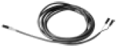 |
QAP1030/UFH | 1854 |
| Electromotor actuators with On/Off valve (only available in AP, UAE, SA and IN) |  |
MVI../MXI.. | A6V11251892 |
| Electromotor On/Off actuators | 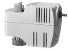 |
SFA21.. | 4863 |
| Thermal actuators (for radiator valves) | 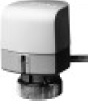 |
STA23.. | 4884 |
| Thermal actuators (for small valves 2.5 mm) | 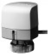 |
STP23.. | 4884 |
| Zone valve actuators (only available in AP, UAE, SA and IN) | 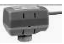 |
SUA21.. | 4830 |
Mechanical design
The room thermostat consists of 2 parts:
- Front panel which accommodates the electronics, the operating elements and the built-in room temperature sensor
- Mounting base with power electronics
The base fits on the conduit box. The front panel slides in the mounting base and snaps on.
RDD310/EH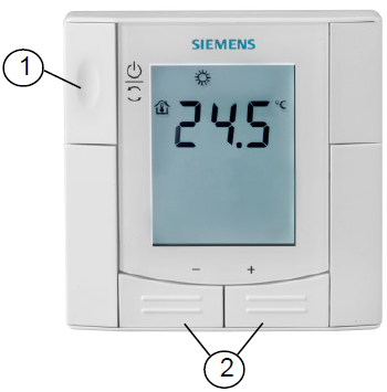
- Operating mode button/Frost Protection
- Button for adjustment of setpoint and control parameters
RDE410/EH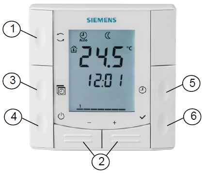
- Operating mode button
- Button for adjustment of setpoints, control parameters, and time of day
- Button for Auto Timer program
- Button for Frost Protection
- Button for setting the time of day and the weekday
- Button for confirmation
Display
The digital display shows the acquired room temperature or the setpoint for the current operating mode, selectable via parameter P06. The factory setting displays the current room temperature.
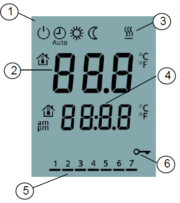
- Operating mode:
- Frost Protection
- AUTO Auto Timer
- Comfort
- Economy
- Room temperature, setpoints, and control parameters
 The symbol for display of the current room temperature
 Heating On
- The current time of day *)
- Weekday 1…7 *)
1 = Monday / 7 = Sunday - Button lock active
Mounting and installation notes
Mount the room thermostat on a recessed rectangular conduit box. Do not mount it in niches or bookshelves, not behind curtains, not above or near heat sources, and not exposed to direct solar radiation. Mount it about 1.5 m above the floor.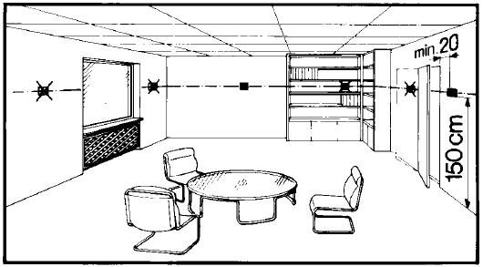
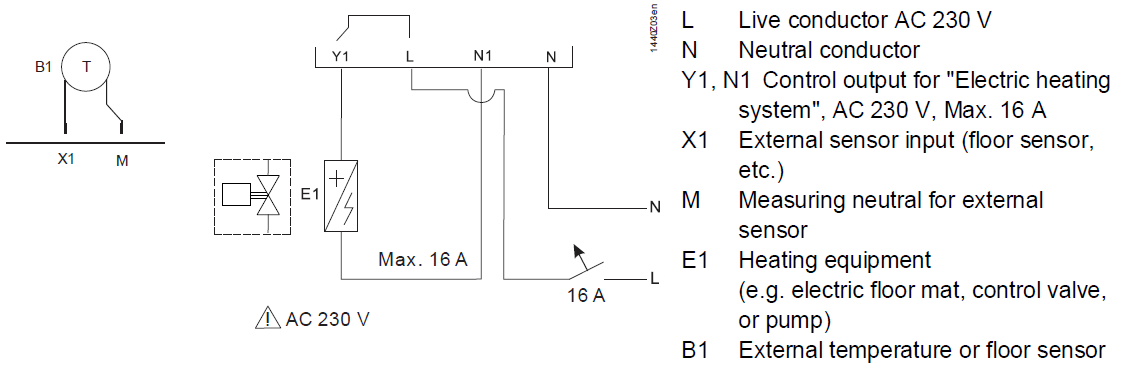
Wiring
See Mounting Instructions CB1M1440xx enclosed with the thermostat.
- Ensure that wiring, protection, and earthing comply with local regulations
- Correctly size the cables to the thermostat and the floor heating system
- If the thermostat cannot accommodate all cables, power must be fed to the system via an external terminal block
- The AC 230 V mains supply line must have a circuit breaker with a rated current of no more than 16 A
- Disconnect from the power supply before removing the unit from the wall
- External inputs X1, M may carry mains potential. The sensor cable must be carefully installed before applying power to the thermostat
Commissioning notes
- Floor heating system
It is mandatory to select the approximate load of the floor heating system via parameter P45 during commissioning. If not sure, the supplier of the floor heating system should be consulted - Floor temperature limitation
For the limitation of the floor temperature via parameter P51, contact the floor supplier. Be aware that the floor temperature is acquired where the sensor head is located - Sensor calibration
If the temperature shown on the display does not agree with the room temperature effectively measured (after at least one hour of operation), the temperature sensor can be recalibrated. For that purpose, adjust parameter P05 - Setpoint and setting range limitation
We recommend reviewing the setpoints and the setpoint setting range (parameters P08…P11) and changing them as needed to achieve maximum comfort and to save energy - Resetting parameters
The factory setting for the control parameters can be reloaded via parameter P71 by changing the value to “On” and confirming by pressing buttons + and – simultaneously. The display shows “888” during reloading
After power is applied, the thermostat carries out a reset during which all LCD segments flash, indicating that the reset was correctly made. After the reset, which takes about 3 seconds, the thermostat is ready for commissioning by qualified HVAC personnel. The control parameters of the thermostat can be set to ensure the optimum performance of the entire system (see below).
Control parameters
| # | Parameter | Factory setting | Setting range |
| Service level | |||
| P02 | Selection of operating mode via the operating mode button | 1 = Comfort – Frost Protection | RDD310/EH: 1 = Comfort – Frost Protection 2 = Comfort – Economy – Frost Protection RDE410/EH: 1 = Auto-Comfort – Frost Protection |
| P05 | Temperature sensor calibration | 0.0 °C | –3…3 °C |
| P06 | Standard temperature display | 0 = Room temperature | 0 = Room temperature 1 =Setpoint |
| P08 | Comfort basic setpoint | 20 °C | 5…40 °C |
| P09 | Min. setpoint limitation in Comfort mode (WminComf) | 5 °C | 5…40 °C |
| P10 | Max. setpoint limitation in Comfort mode (WmaxComf) | 35 °C | 5…40 °C |
| P11 | Heating setpoint in Economy mode | 16 °C | Off, 5…18 °C |
| P14 | Button lock (press the operating mode button for 3 seconds to lock or unlock) | 0 = Disabled | 0 = Disabled 1 = Auto-lock 2 = Manual lock |
| Expert level | |||
| P30 | Switching differential in heating mode | 1 K | 0.5…6 K |
| P38 | External input | 0 | 0 = No input
1 = External sensor input |
| P45 | Heating system load in kW | 2.8 kW | 0…3.6 kW |
| P51 | Floor heating temperature limit | Off | Off, 10…60 °C |
| P65 | The setpoint of heating in Frost Protection mode |
8 °C | Off, 5…18 °C |
| P69 | Temporary setpoint in Comfort mode | Off | Off = Disabled On = Enabled |
| P71 | Reloading factory settings Set the value to “On” and confirm by pressing buttons + and – | Off | Off = Idle On = Reset |
| Diagnostics and test | |||
| d02 | Status X1 | Diagnostics | 0…xx °C = Measured temperature |
| d07 | Software version information | No adjustment | Ux.x |
Parameter settings
Parameter settings at service and expert levels:
The parameters are divided into “Service level” and “Expert level”. The parameter setting mode can be entered as follows: Set the thermostat to “Off/Frost Protection”![]() .
.
Service level only (P02…P14)
Press buttons + and – simultaneously for 3 seconds. Release them and, within 2 seconds, press button + for 7 seconds. Parameters P02…P14 can now be adjusted (service level)
Expert level plus service level (all parameters P02…P71)
Press buttons + and – simultaneously for 3 seconds. Release them and, within 2 seconds, press the button – for 7 seconds. Parameters P02…P71 can now be adjusted (expert level)
In parameter setting mode, the parameters can be readjusted as follows:
- Select the required parameter by repeatedly pressing the button + or –.
- When pressing buttons + and – simultaneously, the current value of the selected parameter starts to flash; change it by repeatedly pressing button + or –.
- When you again press buttons + and – simultaneously, the next parameter is displayed.
- Repeat steps 1 to 3 to display and change additional parameters.
- At the service or expert level: 10 seconds after the last display or setting, all changes are stored and the thermostat will leave parameter setting mode. At the expert level: Press + or – until “End” is displayed. Then, press + and – simultaneously to save the change and exit parameter setting mode.
Disposal
The device is considered an electronic device for disposal in accordance with European Guidelines and may not be disposed of as domestic garbage.
- Dispose of the device through channels provided for this purpose.
- Comply with all local and currently applicable laws and regulations.
Technical data
| Power | supply | Operating voltage | AC 230 V +10/-15% |
| Frequency | 50/60 Hz | ||
| Power consumption | Max. 4 VA | ||
| Outputs | Control output Y1-N1 (NO) Rating |
AC 230 V
Max. 16 (8) A |
|
| External protection for incoming cable Circuit breaker
Circuit breaker tripping characteristic |
Max. 16 A
Type B, C, or D to EN 60898 and EN 60947 |
||
| Inputs | External sensor input (X1-M) Type Temperature range Cable length |
NTC 3 k
0…70 °C Max. 80 m |
|
| Operating data | Switching differential (adjustable)
Heating mode (P30) |
1 K (0.5…6 K) |
| Setpoint setting and range
|
20 °C (5…40 °C) 16 °C (Off, 5…18 °C) 8 °C (Off, 5…18 °C) |
|
| Floor temperature limitation setting range (P51) Factory setting (P38) | Off and 10…60 °C
Off (limitation function not active) |
|
| Built-in room temperature sensor Measuring range
Accuracy at 25 °C Temperature calibration range |
0…49 °C
<±0.5 K ±3.0 K |
|
| Settings and display resolution Setpoints
Current temperature value displayed |
0.5 °C
0.5 °C |
|
| Environmental conditions | Operation
Climatic conditions Temperature Humidity |
As per IEC 60721-3-3
Class 3K5 0 …50 °C < 95% r.h. |
| Transport
Climatic conditions Temperature Humidity Mechanical conditions |
As per IEC 60721-3-2
Class 2K3 – 25…60 °C < 95% r.h. Class 2M2 |
|
| Storage Climatic conditions Temperature Humidity |
As per IEC 60721-3-1 Class 1K3 – 25…60 °C < 95% r.h. |
|
| Standards and directives | EU Conformity (CE) | CE1T1440xx*) |
| RCM conformity | CE1T1440en_C1*) | |
| Protection class | II as per EN 60730-1 | |
| Pollution class | II as per EN 60730-1 | |
| Degree of protection of housing | IP31 as per EN 60529 | |
| Environmental compatibility | The product environmental declaration CE1E1440en*) contains data on environmentally compatible product design and assessments (RoHS compliance, materials composition, packaging, environmental benefit, disposal). | |
| Eco-design and labeling directives | Based on EU Regulation 813/2013 (Eco design directive) and 811/2013 (Labelling directive) concerning space heaters, and combination heaters, the following classes apply: | |
| Application with On/Off operation of a heater | Class, I value 1% | |
| General | Connection terminals | Solid wires 1 x 2.5 mm2 |
| Weight | 0.149 kg | |
| Color of housing front | RAL 9003 white | |
The documents can be downloaded from http://siemens.com/bt/download.
The documents can be downloaded from http://siemens.com/bt/download.
Connection diagrams
Application examples
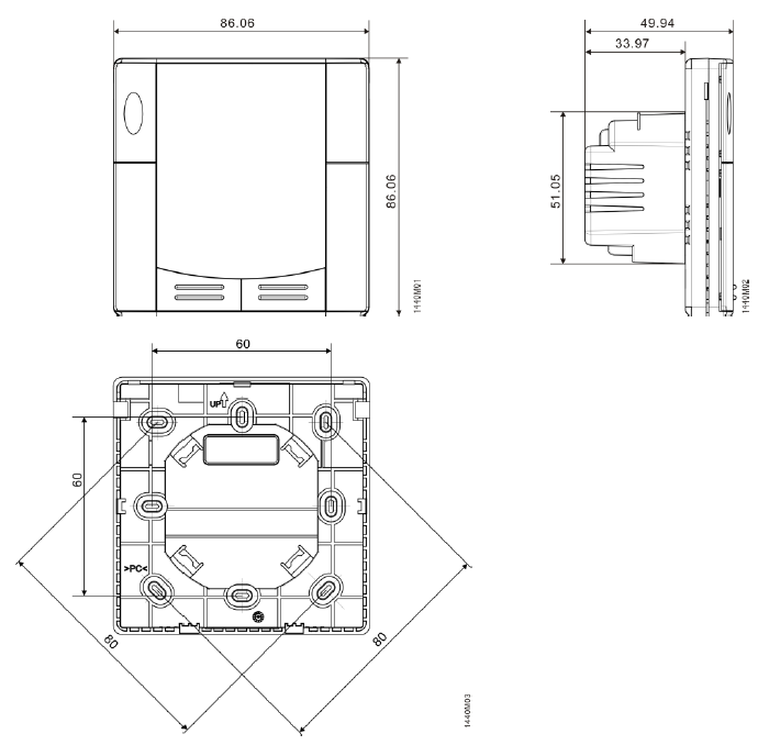
Dimensions (mm)
Remarks
- Heating:
Because of the unavoidable self-heating effects of the electrical current, and loads of more than 10 Amperes connected to the unit can influence the control behavior and temperature accuracy in a negative way. So since this is an electric floor heating product, therefore it is always a must to use an external floor temperature sensor.
Issued by:
Siemens Switzerland Ltd
Smart Infrastructure
Global Headquarters
Theilerstrasse 1a
CH-6300 Zug
Tel. +41 58 724 2424
www.siemens.com/buildingtechnologies
© Siemens Switzerland Ltd, 2013 – 2021 Technical specifications and availability are subject to change without notice.
Reference:
Download manuals:
SIEMENS RDD310EH Flush-mount room thermostat Product Specifications Guide
Other manuals:
SIEMENS RDD310/EH Flush-mount room thermostat Operating Instruction
![]()
SIEMENS RDD310/EH Flush-mount Room Thermostat Product Specifications Guide
Leave a Reply