Pro1 Technologie T721i Thermostat

Pro1 Technologies, Inc.
Springfield, MO 65804
Toll-Free: 888-776-1427 Web: www.pro 1 iaq.com
Hours of Operation: M-F 9 AM – 6 PM Eastern
Thermostat Applications Guide
| Description | |
| Gas or Oil Heat | No |
| Electric Furnace | No |
| Heat Pump {No Aux. or Emergency Heat) | Yes |
| Heat Pump {with Aux. or Emergency Heat) | Yes |
| Multi-stage Systems | No |
| Heat Only Systems | No |
| Heat Only Systems – Floor or Wall Furnaces | No |
| Cool Only Systems | No |
| Millivolt | No |
Power Type
- Battery Power
- Hardwire (Common Wire)
- Hardwire (Common Wire) with Battery Backup
A trained, experienced technician must install this product
Carefully read these instructions. You could damage this product or cause a hazardous condition if you fail to follow these instructions.
INSTALLATION TIPS
Wall locations
The thermostat should be installed approximately 4 to 5 feet above the floor. Select an area with average temperature and good air circulation.

- Do not install thermostats in locations:
- Close to hot or cold air ducts
- That is in direct sunlight
- With an outside wall behind the thermostat
- In areas that do not require conditioning
- Where there are dead spots or drafts (in corners or behind doors)
- Where there might be concealed chimneys or pipes
Installation Tip
Pick an installation location that is easy for the user to access. The temperature of the location should be representative of the building.
Getting to know your thermostat

- LCD
- Glow in the Dark Light Button
- Fan Switch
- System Switch
- Easy Change Battery Door
- Setpoint Buttons
- User Buttons

Important
The low battery indicator is displayed when the AA battery power is low. If the user fails to replace the battery within 21 days, the screen
will only show the low battery indicator but maintain all functionality. If the user fails t replace the batteries after an additional 21 days (days 22-42 since the first “low battery” display) the set points will change to SS°F(Heating) and 8S°F(Cooling). If the user adjusts these setpoints away from these it will hold for 4 hours and then return to either SS°F or 8S0 F. After day 42 the batteries must be replaced immediately to avoid freezing or overheating because the thermostat will shut the unit off until the battery is changed.
Removing the private label badge

Gently slide a screwdriver into the bottom edge of the badge. Gently turn the screwdriver counter clockwise. The badge is held on by a
magnet in the well of the battery door. The badge should pry off easily. Magnet indoor t Does not use force.
About This Badge
All of Our thermostats use the same universal magnetic badge. Visit the company website to learn more about our free private label program.
SUBBASE INSTALLATION
Caution: A Electrical Hazard Failure to disconnect the power before beginning to install this product can cause electrical shock or equipment damage.
Mercury Notice: All of Our products are mercury-free. However, if the product you are replacing contains mercury, dispose of it properly. Your local waste management authority can give Your instructions on recycling and proper disposal.
For vertical mount put one screw on top and one screw on bottom For horizontal mount put one screw left and one screw right.

WIRING
New Thermostat Installation Wiring
- Power supply.
- Use either O or B terminals for the changeover valve.
- An Optional 24 VAC common connection when the thermostat is used in battery power mode.
- A Field-supplied jumper.
Typical 2H/1 C heat pump system

Typical 2H/1 C heat pump system with separate emergency heat
NOTE: In many systems with no emergency heat relay a jumper can be installed between E and W2.
Caution: Electrical Hazard Failure to disconnect the power before beginning to install this product can cause electrical shock or equipment damage.
Warning:
All components of the control system and the thermostat installation must conform to Class II circuits per the NEC Code.
Wiring
- If you are replacing a thermostat, make note of the terminal connections on the thermostat that is being replaced. In some cases, the wiring connections will not be color coded. For example, the green wire may not be connected to the G terminal.
- Loosen the terminal block screws. Insert wires then retighten terminal block screws.
- Place non-flammable insulation into the wall opening to prevent drafts.
|
Brand
Prol |
24V Common
( (optional) |
24V Hot
R |
Changeover in Cooling 0 |
Changeover in Heating
B |
Fan
G |
Emergency Heat E |
Compressor
y |
Auxiliary Heat
W2 |
Malfunction Light
None, Tape Off |
| Arco/Snrder | C | R | 0 | G | E | y | Wl | X | |
| B.D.P. | C | R | 0 | G | E | y | Wl | F | |
| Carrier | C | R | 0 | G | E | y | W2 | L | |
| Coleman | BLCK | RED | V | G | y | W2 | |||
| G.E. B | R | 0 | G | X2 | y | w | |||
| Heil-Quaker | B | R | 0 | G | y | W2 | |||
| Honeywell | C | R | 0 | B | G | E | y | Aux | L |
| Janitrol | C | R | 0 | G | E | y | W2 | ||
| Lennox | X | VNR | R | F | E | M | y | L | |
| Magic Chef | C | R | 0 | G | E | y | w | ||
| Rheem | X | R | B | G | E | y | W2 | L | |
| Ruud | X | R | B | G | E | y | W2 | L | |
| Trane | B | R | 0 | G | X2 | y | w | F | |
| Weatherking | C | R | Yl | G | Wl | E | |||
| Wesco | C | R | Yl | G | E | Wl | W2 | ||
| Westinghouse | X | R/V | 0 | z | G/F | E | Y/C | W/H2 | |
| White-Rodgers | C | R | 0 | B | G | E | y | W2 | L |
| York | B | R | 0 | G | y | w | |||
Note: This cross-reference represents typical systems and is not necessarily representative of your particular
application. Always consult the original equipment manufacturer for proper installation instructions.
TECHNICIAN SETUP

Terminal Designations
- W2 Auxiliary heat relay – Stage 2
- Y Compressor relay – Stage 1
- G Fan relay
- 0 Heat pumP, the changeover valve energized m cooling
- R Transformer power
- The common wire from the system transformer
- B Heat pumP, the changeover valve energized in heating
- E Emergency heat relay
Note:
In many systems with no emergency heat relay a jumper can be installed between E and W2.
Fahrenheit/Celsius Display
Select F or C with the jumper pin on the back of the thermostat. F is for Fahrenheit and C for Celsius
12 or 24 Hour Time
12 or 24 hours (military time) can be selected with the jumper pin.
Important
The RESET button must be pressed after changing any switch or jumper pin setting. Batteries must be installed for this operation
This thermostat has a technician setup menu for easy installer configuration. To setup the thermostat for your particular application:
- Press MENU button
- Press and hold the TECH SET button for 3 seconds. This 3-second delay is designed so that homeowners do not accidentally access the installer settings.
- Configure the installer options as desired using the table below.
Use their keys to change settings and the NEXT STEP or PREV STEP key to move from one step to another.
Note: Only press the DONE key when you want to exit the Technician Setup options.

Swing Setting Tip
The second stage will turn on at 2x the swing set. The second stage will turn off when 1 x the swing is reached. For example, if the swing set is .8 degrees for heating and the thermostat is set at 70°F, the first stage will turn on at approximately 69.2°F. The second stage will turn on at 68.4°F. The second stage will turn off at 69.2°F and the first will turn off at 70.8°F.
Set Time
Follow the steps below to set the day of the week and current time:
- Press MENU
- Press SET TIME
- may If the week will be flashing. Use the
 or
or  key to select the current day of the week
 - Press NEXT STEP
- The current hour is flashing. Use the or the key to select the current hour. When using 12-hour time, make sure the correct a.m. or p.m. choice is selected.
- Press NEXT STEP Use the or key to select current minutes.
- Press DONE when completed
Note
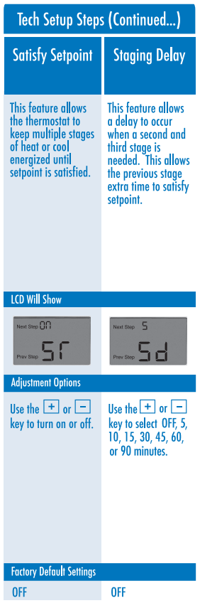
Our Standard staging logic, optional satisfy setpoint, and optional staging deal allow for job-by-job customization that balances comfort, energy efficiency, and equipment longevity.
MOUNT THERMOSTAT & BATTERY INSTALLATION

Mount Thermostat
Align the 4 tabs on the subbase with corresponding slots on the back of the thermostat, then push gently until the thermostat snaps in place.
Battery Installation
Battery installation is recommended even if the thermostat is hardwired (C terminal connected). When the thermostat is hardwired and batteries are installed, the thermostat will activate a compressor delay of 5 minutes when the thermostat detects a power outage from the hardwired power supply.

Important
High-quality alkaline batteries are recommended. Rechargeable batteries or low-quality batteries do not guarantee a 1-year life span.
FEATURES AND SPECIFICATIONS
Filter Change Reminder
If your installing contractor has configured the thermostat to remind you when the air filter needs to be changed, you will see FILT in the
display when your air filter needs to be changed. FILT will be shown in the display after your system has run long enough to require an air
filter change. Resetting the filter change reminder: When the FILT reminder is displayed, you should change your air filter and reset the reminder by holding down the second button from the top left side of the thermostat for 3 seconds.

Understanding Thermostat Staging
Your thermostat will control two stages of heating. The thermostat will try to maintain your comfort setting using the first stage for energy efficiency. The second stage of heating will only be used if your thermostat cannot maintain your comfort setting using only one stage. When the second stage is used you will see +1 in the display.
Specifications
- The display range of temperature ____________ 41 °F to 95°F (5°C to 35°C)
- The control range of temperature ———— 44°F to 90°F (7°C to 32°C)
- Load rating ——————————— 1 amp per terminal, 1.5 amp maximum all terminals combined
- Display accuracy ____________________________ ± 1 °F
- Swing (cycle rate or differential) ______________ Heating is adjustable from 0.2°F to 2.0°F
- Cooling is adjustable from 0.2°F to 2.0°F
- Power source ———————————- 18 to 30 VAC, NEC Class II, 50/60 Hz for hardwire (common wire)
- Battery power from 2 AA Alkaline Batteries
- Operating ambient ——————————— 32° to + 105° (0° to +41 °C)
- Operating humidity—————————— 90% non-condensing maximum
- Dimensions of thermostat ——————— 4.7″W x 4.4″H x 0.8″ D
REFERENCE:
Downlaod Manual: Pro1 Technologie T721i Thermostat Installation Manual
https://device.report/energystar/2396768
Pro1 Technologie T721i Thermostat – Energy Star Certification
Other Manual: Pro1 Technologie T721i Thermostat Operation Manual