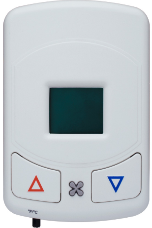
Leviton WS0TH-D00 Programmable Thermostat
WARNINGS AND CAUTIONS
- TO BE INSTALLED AND/OR USED IN ACCORDANCE WITH APPROPRIATE ELECTRICAL CODES AND REGULATIONS.
- IF YOU ARE NOT SURE ABOUT ANY PART OF THESE INSTRUCTIONS, CONSULT AN ELECTRICIAN.
- THERMOSTATS ARE INTENDED ONLY FOR USE INDOORS, IN DRY LOCATIONS, AND WITH PERMANENTLY INSTALLED FIXTURES.
DESCRIPTION
The 24VAC Thermostat provides digital temperature control of heating and cooling–with wireless communication to multiple Leviton devices. It is designed for use with most basic gas/electric furnace/air conditioning units, PTHP/PTAC Systems, 4-pipe, or 2-pipe fan coil systems. Solid-state control outputs allow switching of electronic and relay loads of 1.5 amps. This control operates from a single setpoint with automatic changeover between heating and cooling. The fan cycles on/off with calls for heating or cooling or can operate continuously in either low, medium, or high speed. The control can be placed in economy mode or off mode with 40° freeze protection. Economy mode is enabled and disabled by one or more compatible transmitters.
COMPATIBLE DEVICES
- Key Card Access Switch
- Single Rocker Self-powered Wireless Light Switches
- Dual Rocker Handheld Remote
- Dual Rocker Self-powered Wireless Light Switches
- SLT Wireless Sensor
- Self-powered Wireless Occupancy Sensor
- More transmitters available
COMPONENTS INCLUDED
- Leviton 24VAC Thermostat
- (2) Mounting Screws (6/32” x 3/4”)
- (1) Self-Tapping Screw
- (1) Mounting Bracket
OPTIONAL ACCESSORIES
Horizontal Mounting Plate (not included)
TOOLS NEEDED FOR INSTALLATION
- Phillips Screwdriver
- Electrical Tape
- Wire Nuts
PROGRAMMING THE THERMOSTAT
Connect the thermostat to a 24VAC power source for initial setup. DO NOT CONNECT THE OTHER WIRES UNTIL THIS STEP IS COMPLETE. PREVENT ALL OTHER WIRES FROM TOUCHING DURING THIS PROCESS TO AVOID DAMAGE TO THE THERMOSTAT. DAMAGE DUE TO INCORRECT WIRING WILL VOID WARRANTY. The programming mode has a time limit of 10 minutes. After 10 minutes, the thermostat will resume normal operation. The default values mentioned throughout this section refer to factory programmed settings. If the thermostat has been custom programmed, the defaults may not apply.
NOTE: For programming large numbers of devices, an accessory is available to copy settings from one device to another. Contact Leviton for details.
Configuration Mode
- Place thermostat into programming mode by pressing and holding the UP and DOWN arrows while sliding the °F/°C switch to the opposite side. 00 will appear on the display. Do not use the °F/°C switch again until done programming.
- Press either the up or down arrow button to find the access code 43 then press the fan button.
- Press either the up or down arrow button to scroll through the menu to reach the desired parameter (see below), then press the Fan button.
Exit Menu (Ext):
Equipment Type (E9P): Type of Equipment
- tHP – Default, Trane heat pump, type O reverse valve
- tAC – Trane AC with electric heat
- FHP – Friedrich heat pump, type B reverse valve
- FAC – Friedrich AC with electric heat
- gHP – GE heat pump, type B reverse valve
- gAC – GE AC with electric heat
- AHP – Amana heat pump, type B reverse valve
- AAC – Amana AC with electric heat
- FC – fan coil
Reverse Valve Type (typ): Selects the valve type
- O type – Default, energizes in calls for cooling
- B type – energizes in calls for heating
- Heat Pump or AC (Pt):
- HP – Default, 2 stage heat, single stage cool
- Y = compressor, W = 2nd stage heat
- AC – AC and electric heat
- Y = cool, W = heat
Fan Speed and Operation (FOp):
- 1U – single speed user selectable fan
- 1C – single speed constant fan
- 1A – single speed auto fan
- 2U – Default, two speed user selectable fan
- 2C – two speed constant fan
- 2A – two speed auto fan
Three-speed fan only available for fan coil equipment
- 3U – three-speed user selectable fan
- 3C – three-speed constant fan
- 3A – three-speed auto fan
Compressor Protection (FCp): Selects the compressor protection and high or low speed fan in heating
- CP – Default heat pump, compressor protection and high fan is allowed in heating
- NP – Default fan coil, no compressor protection and high fan is allowed in heating
- CP – compressor protection and high fan is allowed in heating
- nP – no compressor protection and only low fan is allowed in heating
- cP – compressor protection and only low fan is allowed in heating
Continuous Fan Operation (CFL): Selects continuous fan operation
- Dis – Default, normal fan operation
- Ena – continuous low fan in auto or economy modes
- 4. Press either up or down to reach desired change.
- 5. Press fan button to return to program menu.
- 6. Press Up or Down arrow until End / Prog appear on the display.
- 7. Press fan button to save changes and exit the program mode. You will need to re-enter programming mode to access a different code.
Field Programming Mode
- Place thermostat into programming mode by pressing and holding the UP and DOWN arrows while sliding the °F/°C switch to the opposite side. 00 will appear on the display. Do not use the °F/°C switch again until done programming.
- Press either the up or down arrow button to find the access code 79 then press the fan button.
- Press either the up or down arrow button to scroll through the menu to reach the desired parameter (see below), then press the Fan button.
- Press either up or down to reach desired change.
Exit Menu (Ext):
Temperature Scale (Unt): Selects scale parameter that will be shown
- F – Default,°F
- C – °C
Display Temperature (dSP): Select which temperature is shown on display
- SP – Default, display will show setpoint only
- rt – display will show room temperature unless either up or down arrow button is pressed. Then the display will show setpoint.
- Srt – display will toggle between room temperature and setpoint. Display will revert to setpoint when either the up or down arrow button is pressed.
Temperature Control Mode (HAc):
- USr – Default, switch selectable, heat only, auto changeover or cool only
- AUt – auto mode only
- CL – cool mode only
- Ht – heat mode only
Off Function Enabled (OFF ): Selects whether or not thermostat can be turned off by pressing the fan button
- Ena – Default, enabled, press fan button until OFF appears on display
- dis – disabled
Economy Function Enabled (ECo): Selects whether or not thermostat can be manually placed in economy mode by pressing the fan button
- Ena – Default, enabled, press fan button until Eco and ECON appears on display
- dis – disabled
Comfort Setpoint (CS): Selects setpoint default temperature when thermostat powers up or returns to comfort mode from economy mode
- 72.0°F (22.0°C) Default
Programmable Range: 60.0°F to 85.0°F (15.5°C to 29.5°C)
Cooling Limit (LC): Selects minimum room temperature in cooling
- 65.0°F (18.5°C) Default
Programmable Range: 60.0°F to 85.0°F (15.5°C to 29.5°C)
Heating Limit (LH): Selects maximum room temperature in heating
- 85.0°F (29.5°C) Default
Programmable Range: 60.0°F to 85.0°F (15.5°C to 29.5°C)
Freeze Protection (FP): Selects freeze protection enabled or disabled
- Ena – Default, enabled at 40°F
- dis – Disabled
Fan Purge Timer (FPt): Selects the amount of time the fan will continue to run after a heating or cooling call. 30 seconds Default
Programmable Range: 0 (Off) to 180 seconds (3 minutes), in 10 second increment
Clear Logged Data (CLr): Selects whether or not the logged run time data will be
- reset to 0’s
- No – Default, no reset
- Yes – Reset
Setback Ramping (Sbr): Selects setback function to step back to economy setpoints or to go directly to economy setpoints.
- dis – Default, disabled, directly to economy setpoint
- Ena – Enabled, ramps to economy setpoints
- OFF – Directly to Off mode
Ramping Setback Timer (rSt): After setback is initiated, selects the amount of time the setpoint will be stepped back by the degrees per setback
Example: if both parameters are defaulted, the thermostat will step back 1° per every 30 minutes until either the economy cooling limit (EC) or the economy heating limit (EC) is reached 30 minutes Default
Programmable Range: 1 minute to 720 minutes (12 hours), in 15 minute increment
Degrees Per Setback (dPs): Selects the number of degrees per time period that the setpoint will be stepped back
- 1° Default
Programmable Range: 0°F to 3°F, in 0.5°F increments
Economy Cooling Limit (EC): When in economy or remote setback mode, selects the highest room temperature before cooling turns on. Cooling turns off when temperature falls below EC value.
- 85.0°F (29.5°C) Default
Programmable Range: 72.0°F to 99.0°F (22.0°C to 37.0°C), in 0.5°F increments
Economy Heating Limit (EH): When in economy or remote setback mode, selects the lowest room temperature before heating turns on. Heating turns off when temperature rises above EH value.
- 60.0°F (15.5°C) Default
Programmable Range: 41.0°F to 72.0°F (5.0°C to 22.0°C), in 0.5°F increments
Fan Refresh Frequency (FrF): Selects how often the low fan will operate for a fan refresh
- 0 hours Default, disabled
Programmable Range: 0 hours to 24 hours
Fan Refresh Duration (Frd): Selects the length of time the low fan will operate during a fan refresh
- 1 minute Default
Programmable Range: 1 minute to 45 minutes
Cycle Rate Timer (crt): Limits the number of heat/cool cycles per hour
- 6 cycles per hour Default, heat pump
- 8 cycles per hour Default, fan coil
Programmable Range: 0 (Off) to 12 cycles per hour, heat pump
Programmable Range: 0 (Off) to 24 cycles per hour, fan coil
Differential (Dif ): Selects the minimum room temperature above or below setpoint when heating or cooling will turn on or off.
- 0.4°F (0.2°C) Default
- Programmable Range (°F): 0.2, 0.4, 0.6, 0.8, 1.0, 1.2
- Programmable Range (°C): 0.1, 0.2, 0.3, 0.4, 0.5, 0.6
Setpoint Hold Timer (SH): Selects a time limit that the occupant’s setpoint will be saved, when in economy mode.
- 0 hours Default, disabled
Programmable Range: 0 to 24 hours
Fan Hold Timer (HFt): Selects a time limit the high and low fans will operate before automatically returning to auto mode.
- 0 hours Default, disabled
Programmable Range: 0 to 24 hours
Shutdown Delay (Sdd): Selects the amount of time delay between remote shutdown signal and the thermostat going into shutdown mode.
- 0 seconds Default, immediate
Programmable Range: 0 seconds to 200 minutes
- Press fan button to return to program menu.
- Press Up or Down arrow until End / Prog appear on the display.
- Press fan button to save changes and exit the program mode. You will need to re-enter programming mode to access a different code.
Restore Factory Presets
- Place thermostat into programming mode by pressing and holding the UP and DOWN arrows while sliding the °F/°C switch to the opposite side. 00 will appear on the display. Do not use the °F/°C switch again until done programming.
- Press either the up or down arrow button to find the access code 92 then press the fan button.
- All and Erase will appear on the display. Press the fan button again to rest to factory defaults.
- Press Up or Down arrow until End / Prog appear on the display.
- Press fan button to save changes and exit the program mode. You will need to re-enter programming mode to access a different code.
NOTE: This procedure does not affect the stored switches in memory. See the “Programming the Radio Receiver” section for methods to clear this memory.
INSTALLATION
Junction box mounting is highly recommended. For optimal radio performance do not mount or place the receivers close to the floor or inside a metal housing.
INSTALLATION OPTION A:
Heat Pump Configuration
- To avoid risk of fire, shock, or death, TURN OFF POWER at circuit breaker or fuse and verify that it is OFF before installation begins. Make sure that it remains OFF until installation is complete.
- Read all steps for this option before taking any action to install thermostat.
- If retrofitting old thermostat, remove old thermostat, carefully noting the wire connections on the old unit. Record wire color and terminal legends (Cable wire color for Control Feed,
Load Feed, Common, Auxiliary Heat, Compressor, Low Fan, High Fan, and Reversing Valve). Refer to Table A. - Install mounting bracket to the junction box with provided mounting screws.
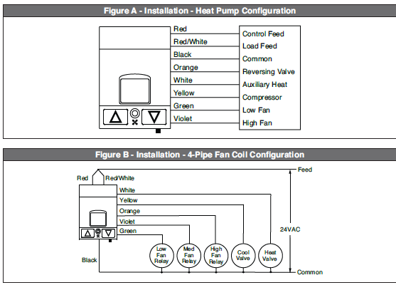
- Wire thermostat according to function as shown in Figure A.
- Push wires into junction box. Rest bottom of thermostat on mounting tabs in mounting plate.
- Push top of thermostat towards wall and secure into place with self-tapping screw.
- Turn power on.
INSTALLATION OPTION B:
4-Pipe Fan Coil Configuration
- To avoid risk of fire, shock, or death, TURN OFF POWER at circuit breaker or fuse and verify that it is OFF before installation begins. Make sure that it remains OFF until installation is complete.
- Read all steps for this option before taking any action to install thermostat.
- If retrofitting old thermostat, remove old thermostat, carefully noting the wire connections on the old unit. Record wire color and terminal legends (Cable wire color for Control Feed, Load Feed, Common, Auxiliary Heat, Compressor, Low Fan, High Fan, and Reversing Valve). Refer to Table A.
- Install mounting bracket to the junction box with provided mounting screws.
- Wire thermostat according to function as shown in Figure B. NOTE: If the mechanical system has only two fan speeds: Green – Low Fan, Violet – High Fan, Orange – Not used.
- Push wires into junction box. Rest bottom of thermostat on mounting tabs in mounting plate. Push top of thermostat towards wall and secure into place with self-tapping screw (included).
- Turn power On.
INSTALLATION OPTION C:
2-Pipe Fan Coil Configuration
NOTE: Continuous fan is not available on 2-Pipe with Aquastat systems. A continuous fan is available on 2-Pipe with electric heat systems.
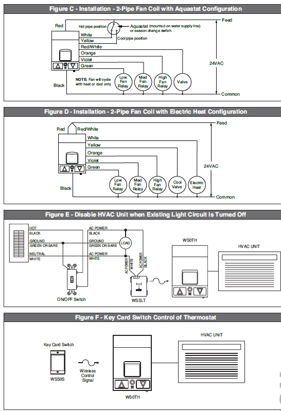
- Follow instructions for a 4-Pipe installation but use Figure C for 2-Pipe Fan Coil with Aquastat or Figure D for 2-Pipe Fan Coil with Electric Heat.
- Push wires into the junction box. Rest bottom of the thermostat on the mounting tabs in the mounting plate.
- Push top of the thermostat towards the wall and secure it into place with a self-tapping screw (included).
- Turn the power On.
PROGRAMMING THE RADIO RECEIVER
The thermostat can be configured to operate with many Leviton transmitters. Depending on the transmitter type and the intended application, the thermostat will need to be programmed to operate in Rocker Mode, Momentary Mode, Toggle Mode, or Scene Mode. Multiple modes can be used with one thermostat. For transmitter installation instructions, see appropriate installation guide. Select the desired Learn Mode below to program the thermostat.
CLEAR MODE:
Clearing the Switch Memory
- In order the clear the switch memory within the thermostat, use the following steps:
- Press and hold the UP and DOWN buttons until CLR appears on the display (approximately 10 seconds).
- This will delete all associated transmitters from the memory.
LEARN MODE 0:
Rocker Mode – Wireless Switch Control of Thermostat
Rocker Mode is usually used with Leviton Wireless Light Switches. The thermostat goes into occupied mode when the top of the rocker switch is pressed and unoccupied mode when the bottom of the rocker switch is pressed.
- Place the thermostat into Learn Mode by pressing and holding the UP and DOWN buttons until LRN appears on the display (approx. 5 seconds). The display will alternate between LRN and 0 indicating that it is in Learn Mode 0 – Rocker Mode.
- Press one of the rockers on the Leviton Wireless Light Switch. The display on the thermostat will briefly display ADD indicating that it has added that transmitter.
- The display will resume alternating between LRN and 0 – add more transmitters as desired for this mode (up to 30). The small digit on the display will indicate the number of receivers in memory for each mode.
- To delete a transmitter from the thermostat, press the wireless light switch again. The display on the thermostat will briefly display DEL indicating that it has deleted that transmitter.
- Exit Learn Mode by pressing and holding the UP and DOWN buttons until LOC appears on the display or wait 30 seconds to normal operating mode. This indicates that all learned transmitters have been locked into memory on the thermostat.
NOTE: These steps are also used for Manual On/Auto Off – when learning a wireless occupancy sensor.
LEARN MODE 1:
Momentary Mode – Keycard Switch Control of Thermostat
Momentary Mode is used with Leviton Wireless Key Card Switches. The thermostat will be in occupied mode when the key card is inserted and unoccupied when the key card is removed.
- Place the thermostat into Learn Mode by pressing and holding the UP and DOWN buttons until LRN appears on the display. The display will alternate between LRN and 0 indicating that it is in Learn Mode 0.
- Press and release the UP button. The display will alternate between LRN and 1, indicating that it is in Learn Mode 1 – Momentary Mode.
- Insert a key card into an Leviton Key Card Access Switch. The display on the thermostat will briefly display ADD indicating that it has added that transmitter.
- The display will resume alternating between LRN and 1 – add more transmitters as desired for this mode.
- To delete a transmitter from the thermostat, remove the key card (if inserted) of a learned switch and insert it again. The display on the thermostat will briefly display DEL indicating that it has deleted that transmitter from memory.
- Exit Learn Mode by pressing and holding the UP and DOWN buttons until LOC appears on the display or wait 30 seconds to normal operating mode. This indicates that all learned transmitters have been locked into memory on the thermostat.
NOTE: These steps are also used for Auto On/Auto Off – Occupancy Sensor Control.
LEARN MODE 2:
Toggle Mode – Toggle Mode is available for future product releases.
- Place the thermostat into Learn Mode by pressing and holding the UP and DOWN buttons until LRN appears on the display.
- The display will alternate between LRN and 0 indicating that it is in Learn Mode 0.
- Press and release the UP button. The display will alternate between LRN and 1, indicating that it is in Learn Mode 1 – Momentary Mode.
- Press and release the UP button. The display will alternate between LRN and 2, indicating that it is in Learn Mode 2 – Toggle Mode.
- Press the transmit button on the desired transmitter. The display on the thermostat will briefly display ADD indicating that it has added that transmitter.
- The display will resume alternating between LRN and 2 – add more transmitters as desired for this mode.
- To delete a transmitter from the thermostat, press the learned transmit button again. The display on the thermostat will briefly display DEL indicating that it has deleted that transmitter.
- Exit Learn Mode by pressing and holding the UP and DOWN buttons until LOC appears on the display or wait 30 seconds to normal operating mode. This indicates that all learned transmitters have been locked into memory on the thermostat.
LEARN MODE 3:
Scene Mode – For Future Product Releases
Specifications
| Specifications | |
| WS0TH | |
| Range | 50-150 feet |
| Frequency | 315 MHz |
| Input Voltage | 24 VAC |
| Max Loads | 1.5 amp/circuit |
| Temperature Monitor Range | 32.0o F to 99.9o F (0o C to 37.7o C) |
| Temperature Set Point Range | 60o F to 85o F (15.5o C to 29.5o C) |
| Operating Temperature | 14o F to 131o F (-10o C to 55o C) |
| Storage Temperature | -4o F to 131o F (-20o C to 55o C) |
| Sampling Rate | Every 5 seconds |
| Display Format | Liquid Crystal Display (LCD) |
| Fan Control | Selectable : Auto Cycle, Low, Medium, High, Economy, Off |
| Memory | Stores up to 30 switch IDs |
| Accuracy | +/- 1o F (0.5o C) |
| Heat/Cool Control | 1 Heat and 1 Cool circuit, Heat pump reversing valve circuit |
| Dimensions | 3.5 x 5.0 x 1.5 inches |
| Radio Certifications | FCC (U.S. SZV-TCM2XXC), IC (Canada 5713A-TCM2XXC) |
TABLES/WIRING DIAGRAMS Table A
NOTE: This table is provided for reference and is not intended to match every situation. Multiple installation options are available. Wiring connections should be made by a qualified HVAC Contractor. If unsure about wire colors or terminal functions, contact a qualified HVAC contractor. If connections are not made properly, damage to equipment or property could result
| Conventional HVAC Systems | |||
| Commonly Used Wiring Terminal Designators | Possible Wire Color | Possible Signal Names/Functions | Comments |
| C | Black | 24VAC Common | From one side of the 24VAC transformer, usually called the common side. |
| R or V | Red | 24VAC Hot | From other side of the 24Vac transformer, usually called the hot side. The thermostat may connect this terminal with W (call for heat) or Y (call for cool), if RH and RC are not used/available. Some thermostats also use this to supply power to themselves. |
| RH or 4 | Red | 24VAC hot usually used for call for heat | Functions as the source of power for the W terminal. The thermostat usually connects this terminal with W when it calls for heat. |
| RC | Red | 24VAC hot usually used for call for cool | Functions as the source of power for the Y terminal. The thermostat usually connects this terminal with Y when it calls for heat. |
| G | Green | Active blower fan | The fan switch on the thermostat usually connects this terminal with R when it is in the ON position. |
| W or W1 or W2 | White | Call for heat | The thermostat usually connects this terminal with R or RH when it calls for heat. The thermostat usually connects this terminal with G when the fan switch is set to AUTO. Some thermostats require a jumper from W to Y if a heat pump is used. Other thermostats might use this as second-stage heating. Sometimes W2 designates auxiliary heating in systems that use heat pumps. |
| Y | Yellow | Call for cool | The thermostat usually connects this terminal with R or RC when it calls for heat. The thermostat usually connects this terminal with G when the fan switch is set to AUTO. Could also be for cooling of first-stage heating on a heat pump. |
| S1 and S2 | Varies | Outside air temperature display | Used to display the outside air temperature on some digital thermostats. |
Systems with Heat Pumps or Staged Heating/Cooling Sub-systems
| Systems with Heat Pumps or Staged Heating/Cooling Sub-systems | |||
| Commonly Used Wiring Terminal Designators | Possible Wire Color | Possible Signal Names/Functions | Comments |
| C | Black | 24VAC Common | From one side of the 24VAC transformer, usually called the common side. |
| R | Red | 24VAC Hot | From other side of the 24Vac transformer, usually called the hot side. The thermostat may connect this terminal with W (call for heat) or Y (call for cool), if RH and RC are not used/available. Some thermostats also use this to supply power to themselves. |
| RH | Red | 24VAC hot usually used for call for heat | Functions as the source of power for the W terminal. The thermostat usually connects this terminal with W when it calls for heat. |
| RC | Red | 24VAC hot usually used for call for cool | Functions as the source of power for the Y terminal. The thermostat usually connects this terminal with Y when it calls for heat. |
| Y | Yellow | Call for cool | The thermostat usually connects this terminal with R or RC when it calls for heat. The thermostat usually connects this terminal with G when the fan switch is set to AUTO. Could also be for cooling of first-stage heating on a heat pump. |
| Y2 | Blue, Orange, Pink | Second-stage cooling | Activates the second stage cooling. |
| W2 or W | Varies | Second-stage heating | Activates first-stage auxiliary heating on a heat pump. |
| G | Green | Active blower fan | The fan switch on the thermostat usually connects this terminal with R when it is in the ON position. |
| E | Varies, blue, pink, gray, tan | Emergency heat relay on a heat pump. Active all the time when selected, usually not used | Disables the heat pump and turns on first-stage auxiliary heating. |
| O | Varies, Orange | Reversing valve | Energize to cool. Switches from heat to cool on heat pumps. |
| B | Varies, blue, black, brown, orange | For GE, York, Trane, and possibly others: 24VAC common | From one side of the 24Vac transformer, usually called the common side. |
| For Rheem, Ruud and Weatherking and possibly others: Activate reversing valve | May be needed on some electronic thermostats or may be needed if you have indicator lamps. | ||
| X | Varies | 24VAC common or emergency heat relay | Check with the manufacturer to be certain. |
| X2 | Varies | Second stage heating or indicator lights on some thermostats | Might be emergency heat relay or miscellaneous contacts. |
| T | Varies, Tan or Gray | Outdoor anticipator reset | Used on GE/Trane/American Standard and some Carrier Products. |
| L | Varies | Service light | |
| S1 and S2 | Varies | Outdoor unit shut-off | Can save energy by disabling the outdoor unit when the outdoor air temperature is such that it would cause the unit to operate inefficiently. |
WARRANTY
LIMITED 2 YEAR WARRANTY AND EXCLUSIONS
Leviton warrants to the original consumer purchaser and not for the benefit of anyone else that this product at the time of its sale by Leviton is free of defects in materials and workmanship under normal and proper use for two years from the purchase date. Leviton’s only obligation is to correct such defects by repair or replacement, at its option, if within such two year period the product is returned prepaid, with proof of purchase date, and a description of the problem to Leviton Manufacturing Co., Inc., Att: Quality Assurance Department, 201 North Service Road, Melville, New York 11747. This warranty excludes and there is disclaimed liability for labor for the removal of this product or reinstallation. This warranty is void if this product is installed improperly or in an improper environment, overloaded, misused, opened, abused, or altered in any manner, or is not used under normal operating conditions or not in accordance with any labels or instructions. There are no other or implied warranties of any kind, including merchantability and fitness for a particular purpose, but if any implied warranty is required by the applicable jurisdiction, the duration of any such implied warranty, including merchantability and fitness for a particular purpose, is limited to two years. Leviton is not liable for incidental, indirect, special, or consequential damages, including without limitation, damage to, or loss of use of, any equipment, lost sales or profits or delay or failure to perform this warranty obligation. The remedies provided herein are the exclusive remedies under this warranty, whether based on contract, tort or otherwise
FCC
FCC COMPLIANCE STATEMENT
Complies with Part 15 of the FCC Rules. Operation is subject to the following two conditions:
- this device may not cause harmful interference and
- this device must accept any interference received, including interference that may cause undesired operation.
Leviton is a registered trademark of Leviton Mfg. Co. in the United States, Canada, Mexico, and other countries. Other trademarks herein are the property of their respective owners.
REFERENCE:
DOWNLOAD MANUALS:
Leviton WS0TH-D00 Programmable Thermostat Installation Instruction
OTHER MANUALS:
Leviton WS0TH-D00 Wireless Thermostat Product Data Sheet

Leviton WS0TH-D00 Programmable Thermostat Installation Instruction