Lennox S30 Smart Thermostat

WARNING
Improper installation, adjustment, alteration, service or maintenance can cause property damage, personal injury or loss of life. Installation and service must be performed by a qualified installer, service agency or the gas supplier
Shipping and Packing List
- 1 – iComfort® S30 Smart Thermostat includes a Smart Hub, HD Display, Mag-Mount and optional use wall plate.
- 4 – Mounting screws (#6 X 1.25” pan head)
- 4 – Wall anchors (alligator flanged solid wall anchors)
- 1 – Installation and setup guide
- 1 – User guide
- 1 – Warranty certificate
General
This iComfort® S30 Smart Thermostat is an electronic communication, color display touchscreen, and 7-day programmable interface which communicates directly with a Smart Hub. The Smart Hub stores system parameters and settings in non-volatile memory (i.e., retains data when electrical power fails or is turned off). After online registration is completed, the system may then be accessed by the homeowner from anywhere using a remote Internet connection via a computer or personal communicating device. The iComfort® S30 Smart Thermostat supports the following equipment and features:
- Wireless bands 802.11b, 802.11g, and 802.11n,
- Three languages are supported (English, Français and Español),
- Air conditioning or heat pump units with up to four stages of heat two stages of compressor operation (two stages of heat pump heating, auxiliary backup heating and emergency heating),
- Variable – capacity / multiple-stage heating and cooling, universal compatibility (gas/electric/heat pump/air conditioner)
- Dual-fuel capable (iComfort® heat pump only) with high and low balance points.
- iComfort Mobile Setup applications are available for IOS 6.0 and higher (App Store) and Android 4.1 and higher (Google Play)
- iHarmony® zoning system (2 – 4 zones),
- Lennox iComfort® Equipment Interface Module (catalog number 10T50) (connects the iComfort® S30 Smart Thermostat to non-communicating indoor and outdoor units.
- Smart Away™ – Uses the iComfort® Thermostat and user mobile device to control the home temperature while unoccupied (geo-fencing).
- Feels Like™ – Control the system using outdoor/indoor temperatures and indoor humidity to create optimal comfort conditions in the home.
- Climate IQ™ – Monitors current climate conditions and automatically removes excess humidity when necessary (requires iComfort® outdoor unit),
- Max Dehumidification – More efficient dehumidification feature for systems with modulating outdoor units (XC/XP20 and XC/XP25), a discharge air temperature (88K38) sensor is used for advanced dehumidification control.
- Perfect Temperature (Single Set Point) – In non-zoning applications this allows a single temperature setting to be used to cool or heat the home.
- Smart Alert Enable – Monitors systems operations such as thermostat set point, temperature reading, climatological design temperatures, system run-times and whether the temperature is going away from set point or towards the set point (system unable to meet demand).
- Humiditrol® Enhanced Dehumidification Accessory (EDA),
- Enhanced defrost control options for Lennox communicating heat pumps using Intellifrost Adaptive Defrost Control, part number 103369-04 or later.
- Performance reports are available through both the dealer and homeowner web portals.
- Installation reports are viewable on the iComfort® S30 Smart Thermostat and dealer web portal. Reports can also be printed or PDF created from the dealer web portal.
NOTE – Due to Lennox’s ongoing commitment to quality, features and options, are subject to change without notice and without incurring liability. Improper installation, adjustment, alteration, service or maintenance can cause property damage or personal injury. Installation and service must be performed by a qualified installer and servicing agency
INSTALLING CONTROL SYSTEM COMPONENTS
Before beginning installation, note the type of equipment, number of stages, and any accessories being installed.
Do
- Read this entire document, noting which procedures pertain to your specific equipment and system requirements.
- Make sure that all wiring conforms to local and national building and electrical codes and ordinances.
Do Not
- Install on voltages higher than 30VAC.
- Short (jumper) across terminals on the gas valve or at the system controls to test installation. This will damage the iComfort® S30 Smart Thermostat and void the warranty.
- Exceed 300 feet (91m) run when using 18 GAUGE thermostat wire or larger.
- Allow load from any thermostat connection to be more than 1 AMP.
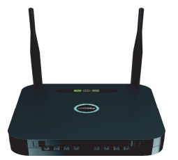
Smart Hub Installation
- Use the following procedure to install the Smart Hub controller.
NOTE – Refer to figures 3 through 11 for making control wiring connections. - Things to consider when installing the Smart Hub:
- Install the Smart Hub near the indoor unit such that there is a direct path to the approximate location of the home Wi-Fi access point (the signal is not blocked by the indoor unit or ductwork, for example).
- The Smart Hub can be attached to a vertical surface such as a wall stud or roof truss web, or to a horizontal surface such as a floor or ceiling joist, or a roof rafter.
- The Smart Hub antennas should be positioned such that they are roughly vertical, no matter the orientation of the Smart Hub, itself.
- Do not install the Smart Hub on the indoor unit, ductwork, or other equipment that could induce vibration in the Smart Hub
- Do not install the Smart Hub on or near large metal objects. This could adversely affect the range and directional coverage of the Smart Hub Wi-Fi signal.
- If the Smart Hub MUST be installed on a metal object, orientate the antennas perpendicular to the metal surface.
- In all cases, the Smart Hub antenna orientation may need to be adjusted to obtain the best Wi-Fi results.

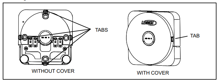
Mag-Mount Installation
- Unpacked the HD Display and Mag-Mount (wall base).
- Install Mag-Mount in the desired location away from direct sunlight or any discharge vents. Use the procedures provided in figure 2, steps A through J.
NOTE – Make sure that Mag-Mount is mounted to a flat surface; if not connection pins to HD Display may not make contact.
Mag-Mount LED
LED: A blue LED is visible on the front of the Mag-Mount when it is connected, powered up, and the HD Display has not been installed (see figure 2, step F) or through the top vent of the mag-mount near the top-left corner. (see figure 2, step J) when the HD Display is installed. The LED has three conditions, steady, flashing and off. Those conditions are:
- Steady – Mag-Mount is receiving power from the Smart Hub.
- Flashing – Mag-Mount is receiving power from the Smart Hub but could be experiencing one of the following conditions:
- The COMM BUS wires are disconnected or are shorted together,
- There has been a software error in the Mag-Mount processor,
- There has been an internal hardware error in the Mag-Mount.
- Off – Mag-Mount is not receiving power from the Smart Hub or there has been a serious Mag-Mount internal hardware/software failure or the blue LED is also off when a HD Display has been installed.

HD Display External Components
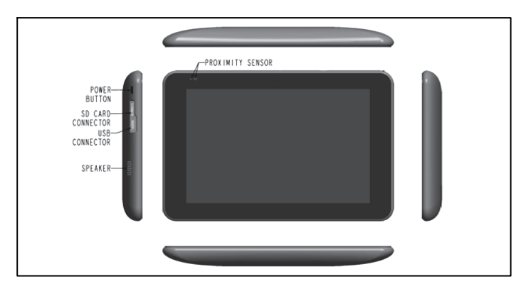
- Proximity Sensor – Detects a person approaching the HD Display. If the HD Display is in Screen Saver mode and the Proximity Detect feature is set to ON, the proximity sensor takes the HD Display out of screen saver mode and returns the home screen when someone approaches.
- Power Button – Resets the HD Display when pressed and held for about 5 seconds.
- SD Card Connector – for future use.
- USB Connector – for future use.
- Speaker – for future use.
HD Display Installation
CAUTION
Magnets located in this product have far-reaching and strong magnetic fields. They could damage TVs and laptops, computer hard drives, credit and ATM cards, data storage media, mechanical watches, hearing aids and speakers. Keep HD Display and Mag-Mount away from devices and objects that could be damaged by strong magnetic fields.
NOTE: Make sure the Mag-Mount cover is reinstalled correctly to the Mag-Mount base. The cover must be flush with the base or could cause power or communication issues. Do not install HD Display/Mag-Mount on outside walls or in direct sunlight.
- Hold the HD Display by the edges, line it up with the Mag-Mount, and move the HD Display toward the Mag-Mount.
- When the magnets in the Mag-Mount attract the HD Display, guide it toward the Mag-Mount and let the magnets pull it into place. Press on the sides of the HD Display to make sure it is completely seated on the Mag-Mount.
- To remove the HD Display from the Mag-Mount, rotate the HD Display right or left (clockwise or counter-clockwise) at least 30 degrees to disengage the plastic hooks and then pull it straight off of the Mag-Mount. Failure to rotate the HD Display before pulling it off of the Mag-Mount may loosen the dry wall anchors or pull the Mag-Mount off of the wall due to the increased forced required to separate the HD Display from the Mag-Mount when it is not rotated.
NOTE – If the HD Display is removed from the Mag-Mount base, the HD Display will shut down and not be able to communicate with the system. System can be controlled from mobile devices or dealer web portal once registration has been completed.- Do not remove the label covering the HD Display screen until after power is applied to the system.
CAUTION - Battery may need to charge before operation. Once the display is connected, instructions may appear within 15 seconds with further detail.
- TO AVOID BREAKING THE GLASS DISPLAY
- Do not apply force directly to the glass display
- Holding the display horizontally
- Center the display cavity on the base
- Press both sides equally until the snaps engage
- AVOID EXCESSIVE FORCE TO THE CLASS DISPLAY
- Do not remove the label covering the HD Display screen until after power is applied to the system.
WIRING FOR CONTROL SYSTEM COMPONENTS
The figure below illustrates the basic Lennox communication control wiring to all system components.

DATS NOTE:
Installation of discharge air temperature sensor (DATS) (88K38) must comply with the following requirements:
- Installed downstream of the heat exchanger or electric heat elements.
- It must be placed in free airflow, where other accessories (such as humidifiers, UV lights, etc.) will not interfere with its accuracy.
- The wiring distance between the IFC, AHC or damper control module and the discharge air sensor should not exceed 10 feet (3 meters) when wired with an 18-gauge thermostat wire. DATS is highly recommended for systems with modulating outdoor units (XC/XP20 and XC/XP25) in order to provide more precise dehumidification operation.
OAS NOTE
The optional outdoor air (temperature) sensor (OAS) (X2658) wiring distance to either the comfort furnace control or comfort air handler control should not exceed 200 feet when wired with an 18-gauge thermostat wire. Installation of OAS must comply with the following requirements:
- Sensor wiring must be run to avoid touching or being close to high-voltage wiring and light ballast.
- Choose a protected outdoor location away from direct sunlight or other heat sources (usually on the north side of the building).
- Ensure that water will neither collect on, nor wash over the sensor.
- Do not locate the sensor near driveways or similar heat‐absorbing masses which may reflect stored heat energy onto the sensor and send inaccurate information to the thermostat.
- Locate the sensor away from attic and soffit vents, or furnace venting pipes.
- Do not locate the sensor directly above an air conditioner or heat pump.
THERMOSTAT WIRING NOTE
Thermostat control wiring runs are as follows:
- The maximum total length of all connections on the system is limited to 1500 feet (450 meters) total.
- The maximum length between comfort controls (indoor to outdoor unit) is 300 feet (90 meters).


CONFIGURATION HEAT SECTIONS ON AIR HANDLER CONTROL
IMPORTANT: PRIOR TO RUNNING THE ICOMFORT S30 SMART THERMOSTAT INSTALLER SETUP, ELECTRIC HEAT MUST BE MANUALLY CONFIGURED!
IMPORTANT: After electric heat strips are installed, the air handler control must be manually configured to detect the number of electric heat sections. (See also 506181-01 for a complete configuration guide.)
This procedure is applicable only to the CBX32MV-XX-230-6-06 and higher and CBX40UHV (all models). To configure the heat strips so that they will be detected by the thermostat:
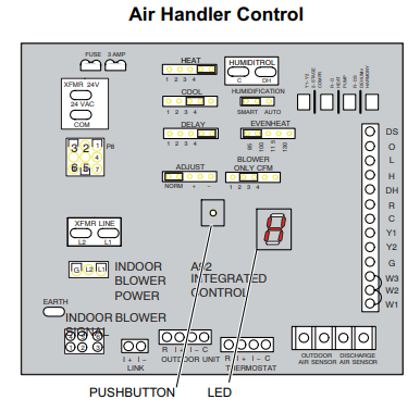
- Power must be applied to the air handler but NOT to the Smart Hub.
Remove all S30 wiring from the indoor unit prior to electric heat discovery. - On the air handler control, the unit should be in idle mode (decimal blinks at 1 Hertz—0.5 second ON, 0.5 seconds OFF.
- Select field test mode—press and hold the push button until solid “–” appears; release button. The display will blink.
- Touch the push button and wait for the display LED to show “H” (capital H), then release the button.
- The air handler control cycles the indoor blower motor “on” to the selected heat speed and stages the electric heat relays “on” and “off” to automatically detect the number of electric heat sections. The air handler control stores the number of electric heat sections, then automatically exits “Field Test Mode”.
- At this point, the iComfort® S30 Smart Thermostat will now detect the heat strip information stored in the air handler control.
- Turn off power and connect all low voltage wiring.
- After commissioning system check to see if you have electric heat or Emergency heat.
SMART HUB OPERATIONS
Lennox-Managed Local Network (Smart Hub Wi-Fi)
A Lennox-managed local network provides a means for a mobile device using the iComfort Mobile Setup application to communicate directly to a Smart Hub. The iComfort Mobile Setup application running on a mobile device cannot reach a Smart Hub through the Internet or through the home Wi-Fi network.
The mobile device must be:
- Wi-Fi-capable,
- Located in the home,
- Use the Smart Hub Wi-Fi to connect to a Smart Hub.
NOTE – A router with Bonjour capabilities is required for this function. Check the router functions if the Smart Hubs does not connect. Apple Bonjour® is an implementation of Zero-configuration networking (Zeroconf), a group of technologies that includes service discovery, address assignment, and host name resolution.
Local Home Wi-Fi Network)
Up to five (5) Smart Hubs, each controlling a separate HVAC system in a home, can be connected together over a local home Wi-Fi network.
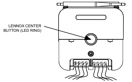
Lennox Center Push Button Switch
The Smart Hub center push button switch:
- Resets the Smart Hub
- Starts the process of creating a special Lennox-managed local network between the Smart Hub and mobile device running the iComfort Mobile Setup application.
NOTE: The only way to add another Smart Hub to the Lennox Manage Network is via the Group ID assignment.
The identity of devices requesting connection to a Smart Hub is rigorously authenticated before connection is allowed to ensure that only iComfort® S30 Smart Thermostat devices connect to a Smart Hub.
Smart Hub Indicators and Connectors

These LEDs have a red LED chip and a green LED chip in the package and can show red, green, or amber colors, steady or flashing.
As a general rule:
- Unlit indicators show there is no power to the Smart Hub or its software has suffered a critical initialization error.
- Steady amber indicators show Smart Hub boot up and self-check processes are in progress or have been completed. Boot up and self checks normally complete rapidly, so amber indicators may appear only briefly (except for the Wi-Fi indicator).
- Flashing amber Wi-Fi indicator shows that the Wi-Fi module check is in progress. Steady amber Wi-Fi indicator shows that the Wi-Fi module has passed its check but is not connected to the home Wi-Fi network.
- Flashing green indicators show acquisition and test of resources across wired interfaces to the Mag-Mount / HD Display and to installed HVAC equipment
- Steady green indicators show that the associated function is connected and operating normally.
- Red indicators show a problem with the associated function.
- Red ALERT indicator shows that a critical alert condition exists. If one of the other indicators is also red, that is the likely source of the alert. If no other indicators are red, the source of the alert is not defined.
Center Push Button Indicator
The center push button has an RGB (red-green-blue) LED backlight that
indicates the Lennox-managed local network communication status of the Smart Hub, and if the Smart Hub is transferring a software image from a flash drive plugged into the USB port. While this LED indicator can show any color, it is currently limited to amber, green, or blue.
When the Smart Hub is in a normal steady state, — when the Smart Hub is in normal day-to-day operation the center push button backlight shows
- Steady blue when there is one or more Smart Hubs in the home and they are not connected to a mobile device running a iComfort Mobile Setup application.
- Steady blue when there is one or more Smart Hubs in the home, but not interconnected.
During various Smart Hub transient states — when the Smart Hub is engaged in a special task that should complete soon — the center push button backlight shows: - Steady amber (briefly) while the Smart Hub conducts self-tests and boots up.
- Flashing amber while software or firmware updates for an iComfort® S30 Smart Thermostat system component or a connected field-upgradable HVAC asset is being transferred from files on a flash drive plugged into the Smart Hub USB port.
- Steady blue while the Smart Hub conducts checks on its internal Wi-Fi module and remote HVAC assets. (Icon indicators show progress.)
- Flashing green when the Smart Hub is attempting a Lennox-managed local network connection with another Smart Hub in the home or with a mobile device running the iComfort® Mobile Setup application.
- Steady green when the Smart Hub is connected to a mobile device running the iComfort Mobile Setup application through a Lennox-managed local network connection. (This is considered a transient state because the mobile device will disconnect from the Lennox-managed network when the task at hand is complete.)
iComfort Mobile Setup Application
This application tool is used by dealers to commission a S30 Smart Thermostat a system using a Wi-Fi-enabled mobile device.
Operating System Requirements
The iComfort Mobile Setup application is available for both IOS 6.0 and higher (App Store) and Android 4.1 and higher (Google Play).
Commissioning
To commission a system using the iComfort Mobile Setup application:
- Download and install the iComfort Mobile Setup application.
NOTE – It is recommended that when using the iComfort Mobile Setup application to commission the system, remove the HD Display from the Mag-Mount before starting. Once commissioning is completed, reattach the HD Display to the Mag-Mount. - Go to the Smart Hub and press the center Lennox button once.
- The center ring LED will start blinking green for two minutes. During that time the Smart Hub will broadcast its Wi-Fi identifier (SSID).
- Go to your mobile device’s Wi-Fi connection tool and locate the Smart Hub Wi-Fi broadcast identifier. The identifier (SSID) is Direct E300-5200 for example.
NOTE – Refer to your mobile device’s owner’s manual on how to use your Wi-Fi Connection tool. - To connect to the Smart Hub use the last eight digits of the Smart Hub SSID as the password (E3005200).
- Once connected to the mobile device the Smart Hub center ring LED turns solid green.
- Start the iComfort Mobile Setup application and make sure you connect to the correct Smart Hub by checking the serial number.
NOTE – The serial number check is only needed if multiple Smart Hubs are shown. For example, if you have three systems and have completed the commissioning of two and while on third unit, the other two Smart Hubs connection data is still listed in the iComfort Mobile Setup application. If you chose the wrong one it will not connect because it would have already stopped broadcasting its connection signal. - Touch the remote in tab on the iComfort Mobile Setup application home screen. This will take you to the commissioning screen.
NOTE – If the system has not been commissioned it will go to the commissioning screen. If the system has already been commissioned it will go to dealer control center. - Once the commissioning is completed, exit the iComfort Mobile Setup application.
- Go to the mobile device’s Wi-Fi tool and manually disconnect from the Smart Hub.
- Once disconnected, the Smart Hub center ring LED turns to a solid blue.
NOTE – If the connection between the iComfort Mobile Setup application and Smart Hub is idle for three (3) minutes, the Smart Hub will auto-disconnect from the mobile device. Repeat procedures to reconnect. - Reinstall the HD Display on the Mag-Mount.
Service
To use the iComfort Mobile Setup application as a service tool, the commissioning of the system must have already been completed.
- Download and install the iComfort Mobile Setup application if not already installed.
- Go to the Smart Hub and press the center Lennox button once.
- The center ring LED will start blinking green for two minutes. During
that time the Smart Hub will broadcast its Wi-Fi identifier (SSID). - If this is the first time connecting to the target Smart Hub then go to your mobile device’s Wi-Fi connection tool and locate the Smart Hub Wi-Fi broadcast identifier. The identifier (SSID) is Direct E300-5200 for example. If your mobile device had already connected previously to the target Smart Hub, then touch the applicable Smart Hub SSID on the list and skip to step F.
NOTE – Refer to your mobile device’s owners manual on how to use your Wi-Fi Connection tool. - To connect to the Smart Hub use the last eight digits of the Smart Hub SSID as the password (E3005200) for example.
- Once connected to the mobile device the Smart Hub center ring LED turns solid green.
- Start the iComfort Mobile Setup application and make sure you are connected to the correct Smart Hub by checking the serial number.
- Touch the remote in the tab on the iComfort Mobile Setup application home screen. This will take you to the dealer control center.
NOTE – If the system has not been commissioned it will go to the commissioning screen. If the system has already been commissioned it will go to the dealer control center. - Once servicing is completed, exit the iComfort Mobile Setup application.
- Go to the mobile device’s Wi-Fi tool and manually disconnect from the Smart Hub.
- Once disconnected the Smart Hub center ring LED turns to a solid blue.
Alternative Method
From the home screen, go to menu > settings > advanced settings > pair Smart Hub to iComfort dealer mobile app selection. It will auto-connect to the dealer app and start you at the dealer control center screen. The following screen will appear and show the status of the connection. Once connected the screen will automatically disappear.
Multiple Smart Hub(s)
When there are multiple Smart Hubs installed in the home, all that are in the same group and are connected to the same home Wi-Fi access point will automatically find and connect to each other through a special Lennox-managed local network running on the home Wi-Fi. Each thermostat can then see and control all the other thermostats in that group.
Restarting Smart Hub
RESETTING SMART HUB – Pressing the center Lennox button for more than five seconds will restart the SMART HUB.
INSTALLER SYSTEM SETUP
IMPORTANT: PRIOR TO RUNNING THE ICOMFORT S30 SMART THERMOSTAT INSTALLER SETUP, AIR HANDLER ELECTRIC HEAT MUST BE MANUALLY CONFIGURED! SEE PAGE 12.
The following procedures are written for the installer setup using the HD Display.
When power is first applied to the system all communicating devices attached to the system (air handler or furnace, outdoor unit or zoning control) will automatically be configured using optimal factory default settings based on system type, capacity and other configuration considerations.
- Boot-up Screen
When power is applied to the system, the HD Display or sometimes referred to as a thermostat will display a welcome screen. For the iComfort Mobile Setup application, refer to page 14 for establishing a wireless connection between the iComfort Mobile Setup application and Smart Hub.
If there is an issue with communication between any component attached to the iComfort® S30 Smart Thermostat, a critical alert message will appear on the screen. The alert message will provide detailed information concerning the possible cause. Once the issue is corrected and power is restored to the system the first screen in the initial setup sequence will appear. Below is an example of a communication error message.
IComfort cannot communicate with the equipment
If the problem persists, please contact your iComfort dealer at 1-800-555-8888 alert
IComfort is unable to connect to the Smart Hub device
For additional support, contact Lennox at 1-800-9-LENNOX or visit www.lennox.com/support - Low Battery Status
If a critically low battery screen is displayed, the system will automatically start charging the HD Display’s internal battery. On the screen, the word “charging” will appear. Once “charging” disappears (typically 3 to 10 minutes) then the display will automatically start-up. - Dealer Info
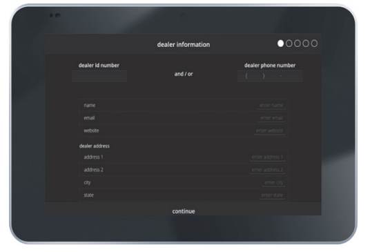
The first screen in the installer system setup sequence is the dealer information screen. Here either the dealer ID and/or phone number can be added. When the system is connected to the Internet, the remaining information is automatically populated by the Lennox server. All information can be entered manually if desired, however.
NOTE – Not all information for this screen is viewable on a single screen. Use a finger to swipe up to access the remaining information on the screen. - Information Required: Dealer ID and/or dealer phone number. Information that can be manually entered is name, email website, and dealer address which includes address 1, address 2, city, state and zip/postal code. Once completed touch continues.
- Warning Screen: If either the Dealer ID or phone number is NOT provided, a warning screen will appear. The warning screen will provide information on the limitation imposed on the system if this information is not provided. Touch no to return to the previous screen to complete the information requested or touch yes to continue.
IMPORTANT: IF THE FOLLOWING INFORMATION IS NOT COMPLETED THE ICOMFORT® S30 Smart Thermostat WILL NOT BE ASSOCIATED TO THE DEALER IN DAVENET. - General Information
On this screen, general information needs to be verified or changed. Touch any item to change its contents. A pop-up screen will appear that will allow the information to be added or changed Information required:- Select desired language (ENGLISH, FRANÇAIS, ESPAÑOL).
- Select country/region.
- Select time and date which includes time, date, time zone and daylight savings time (ON/OFF).
- Temperature unit (Fahrenheit or Celsius). Once completed touch continue.
- Equipment Found Screen
This screen will display any communicating equipment the system has detected (air handler, furnace, outdoor unit, Smart Hub and zoning control) during initial powering up of the system.
NOTE – When a Lennox Equipment Interface Module (EIM) is used and configured either as a furnace or air handler, then the component would appear as either EIM-Furnace or EIM-Air Handler. When using a EIM the outdoor unit may be either a Lennox communicating or any standard 24VAC non-communicating unit.
NOTE – Not all equipment may be visible from the equipment found system screen. Use a finger to swipe up to access additional information (if applicable) listed at the bottom of the system box.
If non-communicating equipment needs to be added, it can be done so from this screen. - Non-Communicating Equipment
When selecting the non-communicating (24VAC) equipment icon a screen will appear listing various equipment that can be added. When selecting an applicable component, a green check will appear next to the item. The capacity selection of the outdoor unit will also be displayed on the screen after selecting the applicable outdoor equipment type.
NOTE – Also a temporary dialog box will appear indicating: Updating – Wait
while we check for dependencies.
NOTE – Selecting an outdoor unit type only appears if a communicating outdoor unit is not detected by the system. Selections are one or two-stage heat pumps or air conditioners. Outdoor unit capacity will also have to be set. Other equipments that can be added are humidifiers and dehumidifiers. Once completed touch done which will display the equipment found screen.
There the additional non-communicating equipment will now be displayed along with the communicating equipment. Once completed touch continues. - Reminders
This screen allows you to set reminders as either disabled or 3, 6, 12, or 24 months and also custom by a specific date. The other option on this screen is to trigger the reminder event either by calendar or actual system run-time. Reminders may be set for replace filter 1, replace filter 2, replace UV blub, replace humidifier pad, PureAir™ maintenance and maintenance reminder. Once a reminder is set for a specific item, touch is done to return to the previous screen. An “expires on a date” will appear next to the item just set. Once completed touch continues. - harmony Zoning
This screen will only appear if the iHarmony® zoning system is detected. This screen allows you to rename each zone using provided preset names or custom names. This screen will not appear if iHarmony® component hardware is not detected by the system.
Touch on any zone to rename it. A screen will display that list several predefined names that can be used which are the master bedroom, guest bedroom, kitchen, living room, media room, dining room, library or custom. When a predefine name is selected, a green check mark will appear next to the selected name. When creating a custom name, touch custom, enter a name and touch back to return to the previous screen. A new unique zone name can be created for all four zones.
Once done, touch done to return to the zoning screen and verify the new name is being used for the specific zone.
Once completed touch continues. - SET UP AIRFLOW PER ZONE
This screen will allow the installer to set up the airflow per zone. The types of circulation per zone are:- Blower Circulation Airflow (gray) which includes total, assigned, minimum and maximum airflow
- Heating Circulation Airflow (red) which includes total, assigned, minimum and maximum airflow
- Cooling Circulation Airflow (blue) which includes total, assigned, minimum and maximum airflow.
Touch on the circled green arrow to touch a specific zone. The zone settings will expand to allow the installer to adjust CFMs for each circulation airflow type. Use the plus and minus buttons to adjust CFMs up and down. Once completed touch continues. The next screen that will appear is the Dealer Control Center.
DEALER CONTROL CENTER
This menu provides access to the dealer for performing various functions as listed below:

Equipment
Selections listed in this section are dependent on system hardware configuration. Not all options will be available.
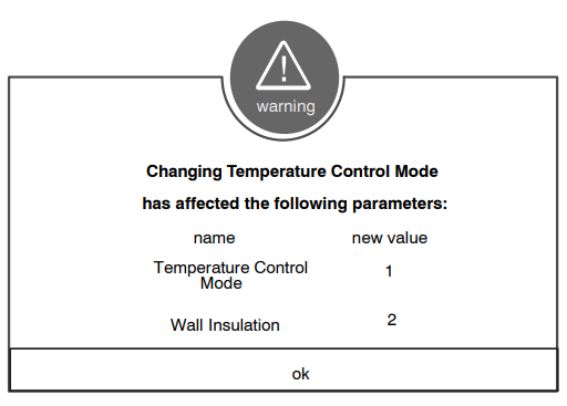
NOTE – When changing the default settings for any parameter, there is a possibility that it will affect the settings for another parameter. If this happens, a pop-up message will be displayed listing the other affected parameters and their new automatically set values.
Smart Hub
The following is a complete list of all possible parameters under the System. Parameters actually available are dependent on the Lennox communicating equipment type detected and non-communicating equipment added.
About
This screen provides information concerning language supported, equipment type name, control software revision, model, control mode number, control serial number, control hardware revision, protocol revision number, device product level, 24VAC average power consumption, 24VAC peak power consumption, compatible devices list, application code memory size and micro-controller part number.
Equipment Name
A unique name can be assigned to this component. The name can be up to 29 characters. A name can consist of letters, numbers, special characters, and spaces. The default name is Subnet Controller.
Temp Reading Calibration
The range is -5.0 to 5.0°F. Default is 0.0°F
If it is determined that the actual temperature being detected at the thermostat is off based on independent readings using other ambient temperature reading devices, the display can be adjusted using this setting.
Humidity Reading Calibration
The range is -10.0 to 10.0%. The default is 0.0%
If it is determined that the actual humidity percentage being detected at the thermostat is off based on independent readings using other humidity reading devices, the display can be adjusted using this setting.
Smooth Setback Recovery (SSR)
When enabled, smooth setback begins recovery up to two hours before the programmed time so that the programmed temperature is reached at the corresponding programmed event time. Assume 12°F per hour for first-stage gas/electric heating and 6°F per hour for first-stage compressor-based heating or cooling. With Smooth Set Back disabled, the system will start recovery at the programmed time. Options are enabled or disabled. Default is enabled.
The SSR set point calculation is as follows:
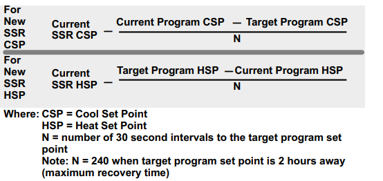
Rules for SSR:
- SSR is enabled when both “Smooth Setback Recovery” is set to enabled (default) and the program schedule is turned on.
- SSR does NOT turn off stage delay timers.
- SSR will NOT change the dead band between heating and cooling modes.
- SSR will not overshoot the target set point.
- SSR will reset if the user updates the program schedule during the active SSR period.
Gas Heating Activation Temp Difference
Range is 0.5 to 10°F. The default is 1.5°F. Adjustments are in increments of 0.5°F. When the system is a dual-fuel and steady-state while operating at full HP demand, this is the amount of °F below the set point that is allowed before allowing to switch to gas heat.
- Electric Heat Control Mode (Single and Two-Stage Lennox iComfort Outdoor Units Only)
In heat pump applications, the electric heat is staged to provide supplemental heat to meet desired comfort levels. When the electric heat section is used in applications that do not have a heat pump, the elements are staged to limit heat so that it meets heating demands only. Options are Standard and EvenHeat. The default is Standard. - even heat Discharge Temp
When in EvenHeat Control Mode, the iComfort® S30 Smart Thermostat will stage the electric heat sections to maintain a constant discharge air temperature. The system must have a discharge sensor connected to the system to show this parameter.
NOTE – Not selectable on Lennox modulating outdoor units. Electric heat elements will be staged on by the demand of the iComfort® S30 Smart Thermostat.
The range is 85 to 130ºF. Default is 85ºF. Adjustments can be made in increments of 15ºF.
Gas Heat Control Mode (SLP98 only)
Options are Staged, Load Tracking Variable Capacity and Variable Capacity. The default is Staged.
Staged
Some furnaces can be configured to provide up to four stages of gas heat operation. When staged heating is chosen, the iComfort® S30 Smart Thermostat allows you to choose between 1, 2, 3 and 4 stages of heat. Single-stage heat: 1st stage provides 100% of full capacity.
- Two-stage heat: 1st stage provides 70% of full capacity; 2nd stage provides 100% of full capacity.
- Three-stage heat: 1st stage provides 60% of full capacity; 2nd stage provides 80% of full capacity; 3rd stage provides 100% of full capacity.
- Four-stage heat: 1st stage provides 35 or 40% of full capacity; 2nd stage provides 60% of full capacity; 3rd stage provides 80% of full capacity; 4th stage provides 100% of full capacity.
Load Tracking Variable Capacity
Load tracking variable capacity will smoothly track the load (sensible temperature changes) up and down and adjust the furnace heating rate both ways.
Variable Capacity
Variable capacity only tracks the load upward (rising temperature). Variable capacity uses the iComfort® S30 Smart Thermostat stage differentials but not stage timers.
Number of Gas Heating Stages
This is applicable to the SLP98V only. Number of selectable stages when Gas Heat Control Mode is set in “Staged” mode. Options are 1 through 4. Default is 4. \
Understanding Modulating Step Change and Steady State PI Gains
Each of these terms has a multiplier (or gain) associated with it called the proportional gain and the integral gain respectively and affect responsiveness and stability
- Standard is a moderate gain suitable for nearly all installations.
- More Aggressive is a set of slightly higher gains that will make the system more responsive to changes, and will try harder to stay on the set point.
This setting may cause some systems to oscillate. - Less Aggressive is a set of slightly lower gains that will make the system less responsive and help to stabilize an oscillating system by sacrificing a small amount of time to set point.
None of the above options will cause the system to end a call if the demand for heating or cooling remains above the minimum capacity of the system since the algorithm is designed to find the demand that allows the system capacity to exactly match the house heating or cooling loss, creating a balance and constant temperature.
Modulating Gas Heating Steady State PI Gain (SLP98V only)
This is applicable to the SLP98V only. Steady-state gain controls the demand when the system is not responding to a sensed temperature change away from the iComfort® S30 Smart Thermostat setting. Options are Less Aggressive, Standard and More Aggressive. Default is Standard. Recommend not changing this setting.
Modulating Gas Heating Step Change PI Gain (SLP98V only)
This is applicable to the SLP98V only. Step change gains to deal with set point changes and affects how fast the system reaches the next set point (Example: Adjustment to the iComfort® S30 Smart Thermostat setting).
Options are Less Aggressive, Standard, and More Aggressive. The default is Standard. Recommend not changing this setting.
Modulating Gas Heating Cycles Per Hour (SLP98V only)
This feature is activated when the structure BTU load is less than the minimum Heat Pump heating capacity of the outdoor unit. The system will be cycled “ON” and “OFF” at the selected cycles per hour to maintain the settings of the iComfort® S30 Smart Thermostat. (This governs how many cycles per hour the system will try to run when it needs to run at less than minimum capacity). Range is 4 to 10 cycles. Default is 6 cycles. Adjustments are in increments of 0.5 cycles.
Modulating HP Heating Steady State PI Gain (Lennox modulating Heat Pumps)
Steady state gain controls the demand when the system is not responding to a sensed temperature change away from the iComfort® S30 Smart Thermostat setting.
Options are Less Aggressive, Standard and More Aggressive. Default is Standard. Recommend not changing this setting.
Modulating HP Heating Step Change PI Gain (Lennox Modulating Heat Pumps)
Step change gains deal with set point changes and affects how fast the system reaches the next set point (Example: Schedule change or adjustment to the iComfort® S30 Smart Thermostat setting). Options are Less Aggressive, Standard and More Aggressive. Default is Standard. Recommend not changing this setting.
Modulating HP Heating Cycles Per Hour(Lennox Modulating Heat Pumps)
This feature is activated when the structure BTU load is less than the minimum Heat Pump heating capacity of the outdoor unit. The system will be cycled “ON” and “OFF” at the selected cycles per hour to maintain the settings of the iComfort® S30 Smart Thermostat. (This governs how many cycles per hour the system will try to run when it needs to run at less than minimum capacity). Range is 3 to 6 cycles. Default is 4 cycles. Adjustments are in increments of 0.5 cycles.
Aux Heating Activation Threshold
This is an adjustment to hasten or delay the aux heat activation. This adjusts how far below the set point the temperature must fall with the HP at 100% before allowing electric heat to come on.
Range is 0 – 10°F with increments of 0.25°F. The default setting is 2.5°F.
Cooling Mode
Options are Normal and Comfort. The default is Normal. When changing to Comfort Mode, several parameters are automatically modified for optimal system operations. The changed parameters are listed on the screen when set to Comfort.
- Normal – This setting cools the home to the desired temperature setting. Once second stage is activated by timer or differential, it will not stage down to first-stage until the next cooling cycle demand.
- Comfort – This is when the system could automatically stage up or down based on the current load demand.
Modulating Cooling Steady State PI Gain (Lennox Modulating Outdoor Units Only)
Steady-state gain controls the demand when the system is not responding to a sensed temperature change away from the iComfort® S30 Smart Thermostatsetting. Options are less aggressive, standard and more aggressive. Default is standard.
Modulating Cooling Step Change PI Gain (Lennox Modulating Outdoor Units)
Step change gains deal with set point changes and affects how fast the system reaches the next set point. Options are less aggressive, standard and more aggressive. Default is standard.
Modulating Cooling Cycles Per Hour (Lennox Modulating Outdoor Units Only)
This feature is activated when the structure BTU load is less than the minimum outdoor unit cooling capacity of the outdoor unit. The system will be cycled “ON” and “OFF” at the selected cycles per hour to maintain the settings of the iComfort® S30 Smart Thermostat. (This governs how many cycles per hour the system will try to run when it needs to run at less than minimum capacity). Range is 3 to 6 cycles hours. Can be adjusted in increments of 0.5. Default is 4.
DAT Offset
(Lennox Modulating Outdoor Units Only and Discharge Air Temperature Sensor Installed)
The default is 0.0°F. The range is -5.0°F to 5.0°F in increments of 0.5°F.
DAT Proportional Gain
(Lennox Modulating Outdoor Units Only)
Default is 10.0. Range is 7.0 to 13.0 in increments of 0.5. This is how the system attempts to reach the discharge air temperature set point. Lennox advises not to make changes to this setting without first contacting Lennox technical support or Lennox field technical consultant.
DAT Integral Gain (Lennox Modulating Outdoor Units Only)
Default is 10.0. Range is 7.0 to 13.0 in increments of 0.5. The indicates how stable the system is attempting to reach the discharge air temperature set point. You may hear the compressor hunting (ramping up and down) adjusting to lower setting will correct.
Lennox advises not to make changes to this setting without first contacting Lennox technical support or Lennox field technical consultant.
Temperature Control Mode
Options are Normal and Comfort. Default is Normal. The Feels-Like feature factors in the outdoor temperature and indoor humidity for a more accurate control of the temperature in the home. Either an outdoor temperature sensor is used or Internet Weather is enabled for this feature to operate. Modifying this setting here will also change the feature status on the user settings screen.
- Normal – This setting cools or heats the home to the desired temperature setting (feels-like) is OFF.
- Comfort – This setting cools or heats the home to the desired temperature setting (Feels Like) is ON. When set to ON, other parameters are modified to optimal settings for this feature. Those setting changes will be listed on-screen when Comfort is enabled.
- Wall Insulation
Options are poor, average and good. Default is average. - Single Setpoint Mode (Non-Zoning System Only)
On the user screens this is referred to as Perfect Temp (Temperature). Options are enabled or disabled. Default is disabled. The Single Set Point (SSP) algorithm allows the user the set only one temperature set point value rather than one value for heating and a different value for cooling. When zoning is present, the following SSP settings are not available. When enabled the following parameters are automatically configured for optimal settings.PARAMETERS DESCRIPTIONS SSP Heating Cancel Coast Counter Increment Slope The range is 0 to 0.75°F. Default is 0.25°F. Adjustments are in increments of 0.125°F SSP Heating Cancel Coast Counter Decrement Slope The range is 0.25 to 2°F. The default is 0.5°F. Adjustments are in increments of 0.125°F SSP Cooling Cancel Coast Counter Increment Slope Range is -0.75 to 0.0°F. Default is -0.25°F. Adjustments are in incre ments of 0.125°F.
SSP Cooling Cancel Coast Counter Decrement Slope Range is -2.0 to -0.25°F. Default is -0.5°F. Adjustments are in incre ments of 0.125°F.
SSP Heating Lockout Outdoor Temp
When the outdoor temperature is above this setting, heating is not al lowed if single set point is running. Range is 50 to 80°F. Default is 70°F. Adjustments are in increments of 1.0°F.
SSP Cooling Lockout Outdoor Temp
When the outdoor temperature is below this setting, cooling is not al lowed if single set point is running. Range is 30 to 60°F. Default is 40°F. Adjustments are in increments of 1.0°F.
- Auto Changeover – Temp Deadband
Prevents the Heating and Cooling from being set closer together than 3ºF or greater than 9ºF (Dead- band).
The range is 3 to 9°F. The default is 3°F. Adjustments are in increments of 1°F. - Max Heat Setpoint
The highest temperature setting that the heat set point can be set on the iComfort® S30 Smart Thermostat.
The range is 60 to 90°F. Default is 90°F. Adjustments are in increments of 1°F. - Min Cool Setpoint
The lowest temperature setting that the cool set point can be set on the iComfort® S30 Smart Thermostat.
Range is 60 to 90°F. Default is 60°F. Adjustments are in increments of 1°F.
Heat Cool Stages Locked In
Heat Cool (H/C) Stages Lock in default is disabled (heat/cool stages are turned off separately). If changed to Enabled, heat/cool stages are turned off together (see figures 13 through 20).
NOTE – For non-variable speed systems only.

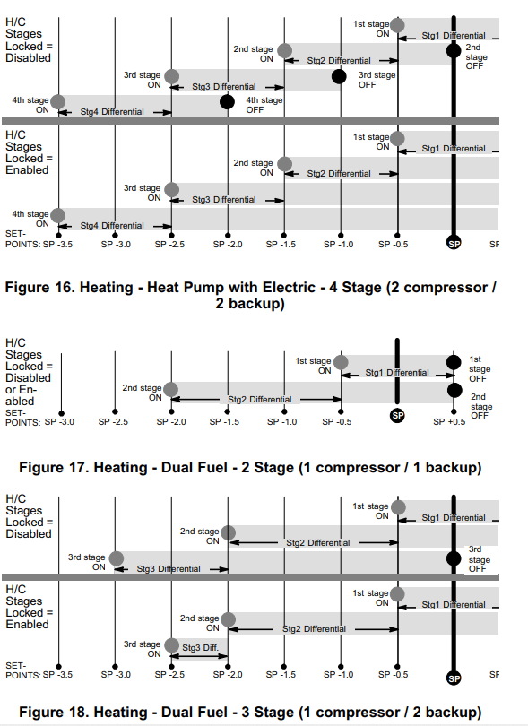
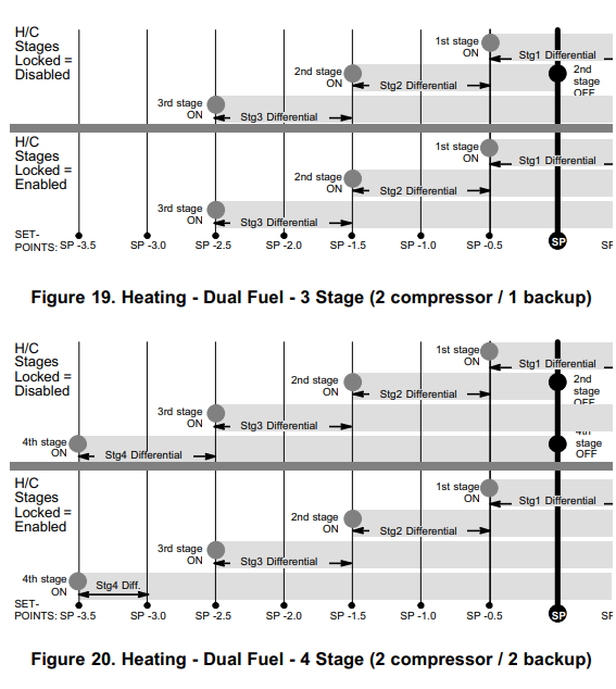
- First through Sixth Stage Differentials
Number of stages in iComfort® S30 Smart Thermostat is dependent on the equipment that is installed.
NOTE: XC/XP25 variable capacity systems will stage electric heat but not on differentials. It will use the iComfort® S30 Smart Thermostat PI logic to stage the electric heat. If the system has a variable capacity furnace or zoning all stage differentials will be ignored. - Stage Delay Timers
- Enabled (default) setting: When enabled all stage delay timers (stages 2 through 6) are enabled and will serve to bring on additional stage(s) of cooling or heating on a timed basis (default 20 minutes)
- Disabled setting: All stages delay timers are disabled. Heat/cool stages are changed based on temperature.
NOTE – The second-stage delay timer (when stage timers is Enabled) is useD for both HEATING and COOLING. However, if the system has a variable capacity furnace, zoning or variable outdoor unit, all stage delay timer will be ignored.
- Second Through Sixth Stage Delays
Second through Sixth Stage Delay timer (where applicable) – If staged delay timers are “Enabled”, the default is 20 minutes but can be programmed from 5 to 120 minutes in 5-minute increments. If the first stage fails to advance the ambient temperature toward the set point by 1.0°F in the programmed delay time, then the second stage is activated. However, if the system has a variable capacity furnace, zoning or variable outdoor unit, all stage delay timer will be ignored. - Lock In 2nd Stage HP by Outdoor Temp (Lennox Two-Stage Heat Pumps Only)
This accessory allows the unit to lock in 2nd stage HP heating when the outdoor temperature goes below the jumper pin setting. Options are off, 40°F (4°C), 45°F (7°C), 50°F (10°C) and 55°F (13°C). Default is off. - Balance Point Control
If system is set up as dual fuel or heat pump and electric heat, the low and high balance point exists. The balance points feature requires that a sensed outdoor temperature is provided to the iComfort® S30 Smart Thermostat.
NOTE – When balance point control is ENABLED, the low and high balance point fields will be turned “ON” and show RED. A message will be displayed asking you to review the low and high balance point settings and save all RED settings. Highlighted fields in RED must be saved to allow exit from that screen. Options are enabled or disabled. Default is disabled. When enabled, both low and high balance points are controlled. - High Balance Point
Setting used to prevent the furnace or electric heat from heating the structure. (Alert 19 – Minor – Notification only – The outdoor temperature is higher than the level where the furnace or electric heat is programmed to heat the home.) Range is -17 to 75°F. Default is 50°F. - Adjustments are in increments of 1°F.
- Low Balance Point
Setting used to prevent the heat pump from heating the structure. (Alert 18 – Minor – Notification only – The outdoor temperature is below the level where the heat pump is programmed to heat the home).
Range is -20 to 72°F. Default is 25°F. Adjustments are in increments of 1°F. - Electric Heat Stages During Defrost
Can increase or decrease the number of electric elements to come on during a call for defrost. (iComfort® S30 Smart Thermostat will have a demand for heat.) Range is 0 to 5 electric heat stages. Default is 2. Adjustments are in increments of 1. - Min Dehumidification Setpoint
Adjustable minimum dehumidification setting.
Range is 40 to 60%. Default is 40%. Adjustments are in increments of 1%. - Humiditrol Comfort Adjust
Options are Maximum Overcooling, Midpoint Overcooling and Minimum Overcooling. Default is Maximum Overcooling.- Maximum Overcooling: Indoor temperature > (greater than) 2°F above heating setpoint.
- Midpoint Overcooling: Indoor temperature > (greater than) HEAT setpoint + COOL setpoint / 2.
- Minimum Overcooling: Indoor temperature > (greater than) 2°F below cooling setpoint.
NOTE – XP25 is not compatible with Humiditrol (EDA).
- Max Humidification Setpoint
Maximum allowed set point for humidification.
Range is 15 to 45%. Default is 45%. Adjustments are in increments of 1%. - Dew Point Adjustment
Range is -15 to 15°F. Default is 0°F. Adjustments are in increments of 1°F. The Dew Point Adjustment can be set from -15% to +15%. These settings allow adjustments to the Dew Point setting for the home. Some homes may require an adjustment to help maintain comfort. If condensation is present on windows, set the adjustment lower, between -15% to -5%. If the home feels dry, set the adjustment upwards, between +5 to +15%. - Auto Changeover – Humidif. Deadband
Prevents the Humidification and Dehumidification settings from being closer together than 5% or greater than 10% (Dead-band). Range is 5 to 10%. Default is 5%. Adjustments are in increments of 1%. - Outdoor Temperature Reading Calibration
Range is -10 to 10°F. Default is 0°F. Adjustments are in increments of 1°F. This will allow for adjustment to the outdoor temperature display when the display temperature is off. Outdoor sensor is required. - Auto Dehumidification Overcooling Threshold
Range is 0 – 10%. Default is 4%. Adjustments are in increments of 1%. This value can automatically be affected by adjusting other parameters. One example would be when enabling Max Dehumidification Overcooling. - Severe Weather Protection (high and low temperature notification)
Options are enabled or disabled. Default is disabled. When enabled either the heat or freezing alert temperature setting will automatically generate a email notification to the homeowner that the applicable condition exist and homeowner interaction is required.
NOTE: Notification is dependent on the thermostat having a active Wi-Fi connection and the user account has been setup and includes a valid email address.- Heat Alert Temperature (high room temperature): This will notified the homeowner when the indoor temperature reaches the setting defined for this parameter. Range is 80°F to 100°F with a factory default of 90°F.
- Freezing Alert Temperature (low room temperature): This will notified the homeowner when the indoor temperature reaches the setting defined for this parameter. Range is 30°F to 50°F with a factory default of 40°F.
- HP Heating Mode (Lennox Modulating Heat Pumps Only)
Options are Normal and Comfort. Default is Normal. The normal setting heats the home to the desired temperature setting. Modify the heating comfort mode to limit minimum compressor speed to 60 – 70 percent range and/or adjust comfort mode CFM.- Normal is when the heat pump will heat the home will providing the highest
efficiency. - Comfort is when the heat pump will deliver warmer air for comfort, but sacrifices on efficiency.
- Normal is when the heat pump will heat the home will providing the highest
- Zoning Gas Heating DAT Cooldown Target
At the end of a gas cycle, the Heat Blower Off-Delay may not be long enough to
completely cool the heat exchanger. This may result in a primary limit trip then,
or at the beginning of the next heat demand. This parameter allows the blower
to run after a gas heat call ends until the discharge air temperature sensor
(DATS) cools to the temperature set in the parameter. If the temperature is set
too low this will cause the temperature in the room to overshoot.
Range is 80 to 90°F. Default is 85°F. Adjustments are in increments of 1°F.
Zoning Anticipated Discharge Air Temperature Adjustment
This parameter setting compensates for a rapid change of the discharge air temperature due to fast changing conditions. It examines the change in the discharge air temperature for the previous 2 minutes and extrapolates or looks forward by the number of seconds set in the parameter and uses this as the DATS value for staging. This parameter setting helps prevent limit trip/frozen coil from occurring.
Range is 0 to 120 seconds. Default is 30 seconds. Adjustments are in increments of 5 seconds. - Zoning Target Supply Air Temp for Cooling
In cooling mode, this setting sets the target discharge air temperature. Range is 40 to 60°F. Default is 45°F. Adjustments are in increments of 1°F. - Zoning Target Supply Air Temp for HP Heating
In heat pump heating mode, this setting sets the target discharge air temperature.
Range is 85 to 110°F. Default is 90°F. Adjustments are in increments of 1°F. - Zoning Supply Air Temp Limit for Cooling
In cooling mode, this setting sets the discharge air temperature low limit. Below this temperature, the cooling is turned off.
Range is 35 to 45°F. Default is 40°F. Adjustments are in increments of 1°F. - Zoning Supply Air Temp Limit for Gas / Electric Heating
In heating mode, this setting sets the target discharge air temperature.
Range is 100 to 160°F. Default is 140°F. Adjustments are in increments of 5°F. - HP Heating Lockout Time
The HP could not get a zone to progress 0.5°F towards the set point in 120 minutes (Code 40 – Minor alert). System will switch to secondary heat source. (Electric heat or furnace in dual fuel applications). Transition back to Heat Pump normal operation when termination setting times out. Range is 60 to 240 minutes. Default is 120 minutes. Adjustments are in increments of 30 minutes.
Zoning Minimum Zone Run-Time
Range is 90 to 600 seconds. Default is 120 seconds. Adjustments are in increments of 30 seconds. - Zone 1 through 4 First Stage Differential
Differential is the temperature between when first stage will cycle ON and cycle OFF. (Example: Zone 1 HD Display is set at 70°F with a 1.0°F differential.
Cooling Demand – cooling will cycle ON when the room temperature reaches 70.5°F and cycle OFF when the room temperature is 69.5°F)
Range is 0.5 to 3°F. Default is 1°F. Adjustments are in increments of 1°F.
NOTE – For Lennox Modulating Outdoor Units differentials are ignored. - Zone 1 through 4 Continuous Blower CFM
Minimum and maximum CFM will be dependent on system component configurations. These parameter values are automatically adjusted to the specific hardware configuration. See iHarmony® zoning system installation instruction for minimum CFMs for specific indoor units.
Zones requesting the fan ON are only allowed while no other zone demand is present. The iComfort® S30 Smart Thermostat will sum all the zone continuous blower CFM requirements and send the command only after positioning the dampers and waiting for the damper close delay period to expire (30 seconds) Continuous blower demands are the lowest priority demands, all other conditioning demands will over-ride the continuous blower demand. Range is 5 to maximum of indoor unit. Default is dependent on tonnage of indoor unit. Adjustments are in increments of 5 CFM. - Zone 1 through 4 Cooling CFM
Minimum and maximum CFM will be dependent on system component configurations. These parameter values are automatically adjusted to the specific hardware configuration. See iHarmony® zoning system installation instruction for minimum CFMs for specific indoor units. Target cooling CFM for a specific zone. Range is 5 to maximum of indoor unit. Default is dependent on tonnage of indoor unit. Adjustments are in increments of 5 CFM. - Zone 1 through 4 Heating CFM
Minimum and maximum CFM will be dependent on system component configurations. These parameter values are automatically adjusted to the specific hardware configuration (See table 9 in iHarmony installation instruction for minimum CFMs for specific indoor units). Target heating CFM for a specific zone. The range is 5 to a maximum of the indoor unit. Default is dependent on the tonnage of indoor unit. Adjustments are in increments of 5 CFM. Adjustments are in increments of 5 CFM. - Reset Smart Hub
Reset Smart Hub (erases Smart Hub settings and restarts installer setup). - Smart Alert Enable
Options are disabled, conservative, medium and aggressive. Default is disabled.- Disable – There is no monitoring of Smart Alert Enable.
- Conservative – The system will wait longer to display any Smart Alert
Enable alarms. These options allow for a minimum chance for false alarms being shown. - Medium (default) – Extensive testing by the Lennox development team to minimize the number of false alarms.
- Aggressive – Will shorten time to display any Smart Alert Enable alarms.
- Smart Alert Enable function monitors:
- Thermostat set point setting
- Temperature reading
- Determine whether the system moving towards the desired temperature setting or is unable to achieve the desired temperature setting.
- Uses local climate design temperatures
- System run times.
NOTE – Smart Alert Enable feature is disabled in a zoning system.
NOTE – Depending on type of system (conventional heating/cooling or heat pump system) and optional equipment not all system settings will be displayed.
Cooling Prognostics
This algorithm will determine whether the unit will run out of capacity during the hottest time of summer. It will look back every day a minimum of three days to see if there is a pattern and compare it to the hottest day on record for that zip code before triggering a notification. It must see a pattern before it will trigger the notification. There may be a component or components that will require attention. The sensitivity (threshold) selection options are OFF, LOW, MEDIUM, and HIGH. The default is HIGH. The alert code notification is 65545.
Group ID
Default is Group ID is 1. Range is 0 to 9. When there are multiple Smart Hubs installed in a home, each can be assigned to a group. Each group can contain up to eight Smart Hubs. All Smart Hubs within a particular group can communicate with all other Smart Hubs in that group over the home Wi-Fi network. Smart Hubs in one group cannot see or interact with Smart Hubs in another group, however.
For example, seven Smart Hubs in a home can be divided up as one in Group 1 and six in Group 2, four in Group 1 and three in Group 2, and so on. Smart Hubs in Group 1 will not be able to see or interact with the Smart Hubs in Group This allows the intentional isolation of the Smart Hub for the master bedroom from the Smart Hub for the children’s area, for example.
If a Smart Hub is set to Group 0, there will be no connectivity with another Smart Hub.
Heat Pump
The following is information on all possible available parameters. Parameters listed are dependent on actual type of heat pump installed.
About
This screen provides information concerning language supported, equipment type name, unit model number, unit serial number, unit nominal capacity, number of heating states, number of cooling stages, heating capacity by stage, cooling capacity by stage, control software revision, control model number, control serial number, control hardware revision, outdoor air temp sensor, protocol revision number, device product level, 24VAC average power consumption, 24VAC peak power consumption, line voltage average power consumption, line voltage peak power consumption, outdoor inverter model number, outdoor inverter firmware version, outdoor fan RPM profile, unit code, compatible devices list, application code memory size and micro-controller part number.
Equipment Name
A unique name can be assigned to this component. Name can be up to 29 characters. Name can consist of letters, numbers, special characters and spaces.
Compressor Short Cycle Delay
(Single and Two-Stage iComfort Outdoor Units)
The range is 60 – 300 seconds. Default is 300 seconds and with an incremental adjustment of 60 seconds.
This feature prevents the compressor from being short cycled any time the compressor is turned “OFF”
Defrost Termination Temp
(Single and Two-Stage iComfort Heat Pumps)
The range is 50 – 100°F. Default is 50°F and with an incremental adjustment of 10°F.
This is the temperature that defrost mode will be terminated. In dual fuel applications (furnace and heat pump), defrost tempering is automatically enabled and operates as follows:
- Furnace will run for 75 seconds ON then after 90 seconds OFF for two cycles.
- After the first two cycles, the furnace will run for 60 seconds ON then cycle OFF for 90 seconds.
- This cycle will be repeated unit the room thermostat is informed by the outdoor control that defrost has terminated.
NOTE -: During the defrost mode, modulating furnaces will operate at their minimum firing rate and staged furnaces will operate on first stage.
Compressor Shift Delay ON / OFF
(Single and Two-Stage iComfort Outdoor Units)
The options are ON or OFF. By default it is set to ON.
- Shift Delay “OFF” – Compressor will not be cycled “OFF” going in and out of defrost.
- Shift Delay “ON” – Compressor will be cycled “OFF” going in and out of defrost.
- High Normal Cooling Airflow (Lennox Modulating Heat Pumps Only)
The range is 450 – 2150 CFM. Default is dependent on unit capacity with an incremental adjustment of 25 CFM.
iComfort® S30 Smart Thermostat values shown are defaults. This value can be adjusted up or down to meet each application’s requirements. - Low Normal Cooling Airflow (Lennox Modulating Heat Pumps Only)
The range is 450 – 2150 CFM. Default is dependent on unit capacity with an incremental adjustment of 25 CFM.
iComfort® S30 Smart Thermostat values shown are defaults. This value can be adjusted up or down to meet each application’s requirements. - High Normal HP Heating Airflow (Lennox Modulating Heat Pumps Only)
The range is 450 – 2150 CFM. Default is dependent on unit capacity with an incremental adjustment of 25 CFM.
iComfort® S30 Smart Thermostat values shown are defaults. This value can be adjusted up or down to meet each application’s requirements. - Low Normal HP Heating Airflow (Lennox Modulating Heat Pumps Only)
The range is 450 – 2150 CFM. Default is dependent on unit capacity with incremental adjustment of 25 CFM. iComfort® S30 Smart Thermostat values shown are defaults. This value can be adjusted up or down to meet each application requirements. - Dehum Airflow Adjustment Adder (Lennox Modulating Heat Pumps Only)
Dehumidification airflow = HUMID Mode CFM table value for a given iComfort® S30 Smart Thermostat demand + dehumidification adjustment adder (High Normal Cooling Airflow CFM x Dehumidification Airflow Adjustment Adder in percentage.
Both these values are in the installer set up under dealer control center > equipment > heat pump. Range is 0 to 30%. Default is 28%.
NOTE – Deactivated in auxiliary dehumidification and Enhanced Dehumidification Accessory (Humiditrol) - Automatic Max Defrost (Single and Two-Stage iComfort Heat Pumps)
This option has two settings, either ON or OFF. Default is OFF. When set to ON, the system will always run at MAX DEFROST when accumulated compressor off time is longer than 30 minutes and ambient temperature is less than 35°F. When ambient sensor temperature is higher than 40°F then defrost termination will be 90°F. - Max Defrost by Weather
(Single and Two-Stage iComfort Heat Pumps)
Options are off and on. Default is off. When set to on, information from the default Internet weather source is used to determine when Max Defrost is used. - Fan Cycling
(Single and Two-Stage iComfort Heat Pumps)
Options are ON or OFF. Default OFF. - Reset Heat Pump
Any installer modifications under the heat pump tab will be reset back to the factory defaults if the reset heat pump option is used.
Air Conditioner
The following is information on all possible available parameters. Parameters listed are dependent on actual type of air conditioner installed.
About
This screen provides information concerning language supported, equipment type name, unit model number, unit serial number, unit nominal capacity, number of cooling stages, cooling capacity by stage, control software revision, control model number, control serial number, control hardware revision, outdoor air temp sensor, protocol revision number, device product level, 24VAC average power consumption, 24VAC peak power consumption, line voltage average power consumption, line voltage peak power consumption, outdoor inverter model number, outdoor inverter firmware version, outdoor fan RPM profile, unit code, compatible devices list, application code memory size and micro-controller part number.
- Equipment Name
A unique name can be assigned to this component. Name can be up to 29 characters. Name can consist of letters, numbers, special characters and spaces. - Compressor Short Cycle Delay
(Single and Two-Stage iComfort Outdoor Units)
The range is 60 – 300 seconds. Default is 300 seconds and with an incremental adjustment of 60 seconds.
This feature prevents the compressor from being short cycled any time the compressor is turned “OFF” - High Normal Cooling Airflow
(Lennox Modulating Air Conditioners Only)
The range is 450 – 2150 CFM. Default is dependent on unit capacity with an incremental adjustment of 25 CFM.
iComfort® S30 Smart Thermostat values shown are defaults. This value can be adjusted up or down to meet each application requirements. - Low Normal Cooling Airflow
(Lennox Modulating Air Conditioners Only)
The range is 450 – 2150 CFM. Default is dependent on unit capacity with an incremental adjustment of 25 CFM. iComfort® S30 Smart Thermostat values shown are defaults. This value can be adjusted up or down to meet each application requirements. - Dehum Airflow Adjustment Adder
(Lennox Modulating Air Conditioners Only)
Dehumidification airflow = “HUMID” Mode CFM table value for a given iComfort® S30 Smart Thermostat demand + dehumidification adjustment adder (High Normal Cooling Airflow CFM x Dehumidification Airflow Adjustment Adder in percentage. Both these values are in the installer set up under System Device/Air Conditioner/High Normal Cooling Airflow).
NOTE – Deactivated in auxiliary dehumidification and Enhanced
Dehumidification Accessory (Humiditrol) - Reset Air Conditioner
Any installer modifications under the air conditioner tab will be reset back to the factory defaults if the reset air conditioner option is used.
Air Handler
The following is information on all possible available parameters for Lennox communicating air handlers.
About
Provides information concerning unit code, language support, equipment type name, unit model number, unit serial number, unit nominal capacity, number of heating states, heating capacity by stage, indoor blower CFM range, control software revision, control model number, control serial number, control hardware revision, discharge air temp sensor, outdoor air temp sensor, protocol revision number, device product level, factory installed transformer, 24VAC average power consumption, 24VAC peak power consumption, line voltage average power consumption, line voltage peak power consumption, compatible devices list, applicable code memory size, and micro-controller part number.
- Equipment Name
A unique name can be assigned to this component. Name can be up to 29 characters. Name can consist of letters, numbers, special characters and spaces. - Electric Heating Airflow
The range is 1560 to 2150 CFM. Default is dependent on unit capacity with an incremental adjustment of 5 CFM.
Range of operation of the indoor blower during electric heat operation. - Low Cooling Airflow
The range is 450.0 to 2150 CFM. The default is based on cooling demand with incremental adjustments of 25 CFM.
Range of operation of the indoor blower during low cooling operation. - High Cooling Airflow
The range is 1560 to 2150 CFM. Default is based on cooling demand with an incremental adjustments of 25 CFM.
Range of operation of the indoor blower during high cooling operation. - Airflow Profile – Cooling
Options are:- 1 – No delays.
- 2 – ON: No delays; OFF: 45 sec delay.
- 3 – ON: 82% – 7-1/2 minutes; OFF: No delays.
- 4 – ON: 50% – 30 seconds at 82% – 7-1/2 minutes at 100% and finish cycle 50% / 30 seconds off.
- Low HP Airflow
Information below is example only and exact air flow range is dependent on equipment tonnage. Use your example and add adjustment increments of +/-25 CFM.
Example: The range is 450 – 600 CFM. Default setting is depending on unit tonnage. Can be incrementally adjusted by 25 CFM.
Range of operation of the indoor blower during low heat pump operation. - High HP Airflow
The information below is example only and exact airflow range is dependent on equipment tonnage. Use your example and add adjustment increments of +/-25 CFM
Example: The range is 800 -1100 CFM. Default setting is depending on unit tonnage. Can be incrementally adjusted by 25 CFM.
Range of operation of the indoor blower during high heat pump operation. - Continuous Indoor Blower Airflow
The range is 450 to 2150 CFM. Default is dependent on component match-up.
Incremental adjustments are made in 5 CFM.
Range of operation of the indoor blower during continuous blower operation.
NOTE – All iComfort parameter default CFM values are based on Air Handler
Control (AHC) DIP switch setting (non-communicating value) prior to power up.
This dip switch settings are use and calculated using CFM conversion tables. They are then rounded up to closest number on 25 CFM resolution. Any DIP switch changes made after power up are ignore. - Heating Indoor Blower Off Delay
The range is 0 – 10 seconds. Default is 10 seconds with an incremental adjustment of 1 second.
Heating Indoor Blower OFF Delay (Electric Heat only -Blower runs at continuous air CFM setting during delay timing period) - Heating Indoor Blower On Delay
The range is 0 – 5 seconds. Default is 0 seconds with an incremental adjustment of 1 second. - Cooling Indoor Blower Off Delay
The range is 0 – 30 seconds. Default is 0 seconds with an incremental adjustment of 2 seconds. - Cooling Indoor Blower On Delay
The range is 0 – 10 seconds. Default is 2 seconds with an incremental adjustment of 1 second. - HP Indoor Blower Off Delay
The range is 0 – 60 seconds. Default is 45 seconds with an incremental adjustment of 5 seconds.
Heat Pump Indoor Blower OFF Delay (Heat Pump only – Blower runs at continuous air CFM setting during delay timing period) - HP Indoor Blower On Delay
The range is 0 – 30 seconds. Default is 0 seconds with an incremental adjustment of 5 seconds. - Reset Air Handler
Any installer modifications under the air handler tab will be reset back to the factory defaults if the reset air handler option is used.
Furnace
About
This screen provides information on unit code, language supported, equipment type name, unit model number, unit serial number, unit nominal capacity, number of heating stages, heating capacity by stage, indoor blower CFM range, control software revision, control model number, control serial number, control hardware revision, discharge air temp sensor, outdoor air temp sensor, protocol revision number, device product level, factory installed transformer, 24VAC average power consumption, 24VAC peak power consumption, line voltage average power consumption, line voltage peak power consumption, compatible devices list, application code memory size and micro-controller part number.
- Equipment Name
A unique name can be assigned to this component. Name can be up to 29 characters. Name can consist of letters, numbers, special characters and spaces. - Low Cooling Airflow
The range is dependent of indoor unit model and size. Default is based on cooling demand with Incremental adjustments of 25 CFM.
Range of operation of the indoor blower during low cooling operation. - High Cooling Airflow
The range is dependent of indoor unit model and size. Default is based on cooling demand with an Incremental adjustments of 25 CFM.
Range of operation of the indoor blower during high cooling operation. - Airflow Profile – Cooling
Options are:- A – ON: 50% – 30 seconds at 82% – 7-1/2 minutes at 100% and finish cycle 50% / 30 seconds off.
- B – ON: 82% – 7-1/2 minutes at 100% and finish cycle off.
- C – ON: 100% – No delays; OFF: 45 seconds.
- D – no delays.
- High HP Airflow
Range is 800.0 to 1100.0 CFM. Default is 967.0 CFM. - Continuous Indoor Blower Airflow
The range is 450 – 2000 CFM with a default setting based on equipment type match-up. Adjustments are in increments of 5 CFM.
NOTE – All iComfort parameter default CFM values are based on Furnace Control (IFC) DIP switch setting (non-communicating value) prior to power up. This dip switch settings are use and calculated using CFM conversion tables. They are then rounded up to closest number on 25 CFM resolution. Any DIP switch changes made after power up are ignore. - Dehumidification Airflow %
Range is 60.0 to 80.0%. Default is 70.0% - Heating Indoor Blower Off Delay
The range is 60 – 180 seconds with a default setting base on equipment type match-up. Adjustment are increments of 10 seconds. - Heating Indoor Blower On Delay
The range is 15 – 45 seconds with a default setting base on equipment type match-up. Adjustment are increments of 5 seconds. - Cooling Indoor Blower Off Delay
The range is 0.0 – 30.0 seconds with a default setting base on equipment type match-up. Adjustment are increments of 10 seconds. Default is 0.0 seconds. - Cooling Indoor Blower On Delay
The range is 0.0 – 10.0 seconds with a default setting base on equipment type match-up. Adjustment are increments of 1 second. Default is 2.0 seconds. - HP Indoor Blower Off Delay
The range is 0.0 – 60.0 seconds with a default setting base on equipment type match-up. Adjustment are increments of 5 seconds. Default is 45.0 seconds. - HP Blower On Delay
The range is 0.0 – 30.0 seconds with a default setting base on equipment type match-up. Adjustment are increments of 5 seconds. Default is 0.0 seconds. - Heating Airflow Control Type
Options for this setting are fixed CFM or fixed DAT (discharge air temperature).
Default is dependent on equipment type match-up.
Fixed CFM is selected as the Heating Airflow Control Type (parameter default selection), the circulator will operate at a CFM that is linearly interpolated between Low Heating Airflow and High Heating Airflow based on the current IFC firing rate. For example, if the firing rate is 60% and Low Heating Airflow and High Heating Airflow were set to 500 CFM and 900 CFM respectively (both parameter values are set during the IFC commission), the circulator will run at 297 CFM (= 500+ (900-500) *(60-40)/(100-40)) – assuming 40% minimum fire rate - Fixed Discharge Air Temperature (DAT) control when selected as Heating Airflow Control Type, the IFC will vary circulator at a CFM to maintain a set Discharge Air Temperature (DAT). For example if the firing rate is 60% and Low Heating DAT and High Heating DAT were set to 115°F and 130°F respectively (both parameter values are set during the IFC commission), the IFC
When Fix DAT is enabled, the following parameters are available:Parameter Name Description Low Heating Discharge Temp
Range is 105 to 135°F. Adjustable in increments of 5F. Default is 120°F. High Heating Discharge Temp Range is 115 to 145°F. Adjustable in increments of 5F. Default is 130°F. - Low Heating Airflow
Both range and default setting is based on equipment type match-up.
Adjustments are in increments of 25 CFM. This value is automatically adjusted by the system based on heating airflow control type used. - High Heating Airflow
Both range and default setting is based on equipment type match-up. Adjustments are in increments of 25 CFM. This value is automatically adjusted by the system based on heating airflow control type used. - Reset Furnace
Any installer modifications under the furnace tab will be reset back to the factory defaults if the reset furnace option is used.
Zoning Control
About
This provides information on unit code, language supported, equipment type name, control software revision, control model number, control serial number, control hardware revision, protocol revision number, device product level, 24VAC average power consumption, 24VAC peak power consumption, compatible devices list, application code memory size, micro-controller part number, max number of zones, supported damper types, number of damper positions, zone temp sensor 1, zone temp sensor 2, zone temp sensor 3 and zone temp sensor 4.
- Equipment Name
A unique name can be assigned to this component. Name can be up to 29 characters. Name can consist of letters, numbers, special characters and spaces.
Zones 1 through 4 Temp Reading Calibration
Allows adjustment to temperature reading displayed on zone thermostat. - Reset Zoning Control
Any installer modifications under the zoning control tab will be reset back to the factory defaults if the reset zoning control option is used.
Thermostat (HD Display)
About
This screen provides information concerning model number, serial number, hardware revision, software revision, language support and equipment type name.
Screen Locked
Options are unlocked, partially locked and locked. Default is unlocked.
- Display Outdoor Weather
Options are on and off. Default is off. - Display Air Quality
Options are on and off. Default is off. Air Quality is displayed under the weather display. Touch the Weather icon on the home page to see the current air quality. - Outdoor Temperature Source
Options are off, Internet (AccuWeather) or sensor. Default is Internet (AccuWeather). - Display Indoor Humidity
Options are on and off. Default is off. - Screen Saver
Options are off, weather, power save and logo. Default is off. - Auto Brightness
Options are on and off. Default is off. - Brightness Value
The brightness range is 0 – 100. Default 80. Touch either the + or – button to increase or decrease the setting. - Proximity Control
Options are ON and OFF. Default is OFF. Is used to wake-up the display from screen saver mode when motion near the HD Display is detected. - Wide Setpoint
Options are ON and OFF. Default is OFF. This allows a wider low and high temperature. Normal range is 60 to to 90°F. When this parameter is set to ON, the range is 40 to 100°F. This feature can also be set through the user interface setting screen. From the home screen go to menu > settings > heat & cool (or it may be just heat or cool) > wider set-point range. - Reset thermostat
Resets the thermostat settings to factory default.
Mag-Mount
About
This provides information on equipment type name, control hardware revision, control software revision, control serial number and control model number.
Add / Remove Equipment
This selection allows the installer to add or remove non-communicating 24VAC
controlled equipment such as outdoor units, humidifiers and dehumidifiers.
Reset
Selections on this screen allow S30 iComfort and HVAC equipment to be restarted, reconfigured, or reset to factory defaults.
- Restart Smart Hub
Restarts the Smart Hub. - Re-configure System
Re-configure HVAC system. - Reset HVAC Equipment
Resets all HVAC equipment. - Factory Reset Thermostat
Resets thermostat to factory default settings. - Factory Reset Smart Hub
Resets Smart Hub parameters back to factory default.
Notifications
See table on page 48 for a complete list of all alert codes.
Tests
Verify Airflow Per Zone is the first screen to appear under this selection. If no zoning is installed, zone airflow settings will be for zone 1 only. If zoning equipment is detected by the system then zones 1 through 4 will be listed. These screens allow for verification and modification of CFMs for blower, heating and cooling circulation. Touch continue to proceed to the next screen. Select Test to Run is the next screen to appear. Depending on hardware present, various tests are available. By default all items to be tested are enabled. Selecting a specific test will un-check the item. When a specific set of tests are completed the results will be displayed on the screen next to the tested item. Touch continue to proceed to the next set of test items. Once all tests are completed press done to return to the touch tests to run screen. Touch the left arrow at the top left side of screen to return to the Dealer Control Center.
![]() Diagnostics
Diagnostics
This screen allows the installer to test all major communicating components of the system indoor unit (air handler or furnace), outdoor unit (air conditioner or heat pump) and zoning control (if applicable). Pressing the stop diagnostics button will pause the diagnostic function. Touch the left arrow at the top left side of screen to return to the Dealer Control Center.
 Installation Report
The overview screen provides information on dealer and customer information. Also included under day of install section is information on conditions at the time of installation. Information includes date, time indoor and outdoor temperatures and indoor humidity. Under equipment, system, indoor/outdoor and zoning model number, serial number and firmware information is displayed.
Other menus items include system indoor and outdoor units and zoning control parameter settings.
NOTE – Installation Report is not available until after exiting the dealer control center following commissioning. Return to the dealer control center from the home screen to view the installation report.
Information
- Dealer — Information
The dealer information screen will appear. The next screen will be for dealer information. Here either the dealer ID or phone number can be added. Once the system is connected to the Internet, the remaining information is automatically populated. Not all information for this screen will be viewable. Touch and hold and then drag up to access the remaining information on the screen. Information Required: Dealer ID and / or dealer phone number. Information that can be manually entered is name, email website, dealer address which includes address 1, address 2, city state and zip/postal code. Once completed, Touch the left arrow at the top left side of screen to return to the Dealer Control Center.
IMPORTANT: ADDING DEALER INFORMATION WILL ENSURE THE ICOMFORT® S30 SMART THERMOSTAT IS ASSOCIATED WITH YOUR DAVENET ACCOUNT WHEN CONNECTING TO THE LENNOX SERVER. Warning Screen: If the dealer ID or phone number is not provided, a warning screen will appear. The warning screen will provided information on the limitation imposed on the system if this information is missing. Touch no to return to the above screen to complete the information requested or press yes to continue. - General Information
On this screen general information needs to be verified or changed. Touch any item to change its contents. A pop-up screen will appear that will allow the information to be added or changed. - Information Required:
- Select desired language (ENGLISH, FRANÇAIS, ESPAÑOL).
- Select country / region.
- Select time and date which includes time, date, time zone, daylight savings time (ON/OFF)
- Temperature unit (Fahrenheit or Celsius). Once completed press continue.
Home Address
On this screen general information needs to be verified or changed. Touch any line item to change its contents. Information to be added is address 1, address 2, state, city and zip/postal code.
Complete the requested information and press the continue button.
Dehumidification
For firmware version 3.15 and later, all controls for dehumidification under menu > settings > humidity. Under Humidity Control, select dehumidify to enable dehumidification. By default it is disabled.
When dehumidify is enabled, the options are as follows and are dependent on equipment type and accessory installed.
Dehumidification Setting Options
- Normal — Recommend when the air outside is not too humid.
- Max —
- Single and Two-Stage Outdoor Units or Modulating outdoor units without a Discharge Air Temperature Sensor (DATS) Installed. Recommend when outdoor air is excessively humid. May cool your home below the set temperature.
NOTE – Recommend use of discharge air temperature sensor (DATS) catalog number 88K38 when modulating outdoor units are used. - Modulating Outdoor Units with DATS installed. Recommended when outdoor air is excessively humid. Adjusts cooling based on duct sensor data. May cool your home below the set temperature.
- Climate IQ (Auto) — Automatically adjusts fan speeds and cooling power based on local climate conditions, using Climate IQ technology. May cool your home below the set temperature.
- Single and Two-Stage Outdoor Units or Modulating outdoor units without a Discharge Air Temperature Sensor (DATS) Installed. Recommend when outdoor air is excessively humid. May cool your home below the set temperature.
- Overcooling
Slide bar adjust with a range of 0°F to 4°F. Only available when Max or Climate IQ is selected. - Dehumidification Set Point
Slide bar adjust with a range of 40% to 60%. - Advanced Dehumidification Descriptions
See table 1 for detail information concerning system operations when using normal, Max or Climate IQ settings.
Table 1. Dehumidification Control Modes of Operations
| Normal | √ Both Staged and Modulating Outdoor Units: Dehumidifies while servicing a cooling demand and will not overcool. The overcool slider is hidden from the user. Modulating units use the “comfort” table to run the system, regardless of the presence of a discharge air temperature sensor (DATS). | |||
|
Max |
√ Staged Outdoor Unit: If at the start or during a cooling call, the humidity is above the relative humidity set point then the unit dehumidifies during the cooling demand. If at the time the cooling call terminates, the humidity demand is not satisfied, overcooling will occur up to the overcooling slider setting in an attempt to satisfy the dehumidification demand. Once the room temperature reaches the overcooling set point. If the system still has a dehumidification demand, the system keeps using the overcooling set point as its operating cooling set point (will not wait for the tempera ture to rise to the normal cooling set point to run again) until the dehumidification demand is satisfied
√ Modulating Outdoor Unit: |
|||
| ˃ Modulating units work as described as staged outdoor units and if a discharge air temperature sensor (DATS) sensor is installed, the DAT PI is used to control the compressor speed to maintain a cold coil for optimized dehumidification. | ||||
| ˃ If a DATS is not installed, the system runs using the outdoor unit’s “comfort” tables during dehumidification. | ||||
| √ Staged Outdoor Unit: At the end of a cooling call, if the humidity is above the set point by a certain amount (Basic to Precision Threshold parame ter), then overcooling to the overcooling slider setting occurs to satisfy the dehumidification demand. Once the room temperature reaches the overcooling set point, if the system still has a dehumidification demand, the system keeps using the overcool set point as its operating cooling set point (will not wait for the temperature to rise to the normal cooling set point to run again) until the dehumidification demand is satisfied. | ||||
| √ Modulating Outdoor Unit: | ||||
| ˃ If at the start or during a cooling call, the humidity level is below the relative humidity set point by more than 10%, then the mode becomes “Dry” such that the blower CFM is increased to the “Dry” table setting. | ||||
|
Dehumidification Only |
Climate IQ (Auto) |
˃ If a cooling call starts with the humidity level below the relative humidity setpoint, or if during a cooling call, the humidity level is between the dehumidify off relative humidity point and the relative humidity set point -10, then standard cooling runs to satisfy the cooling demand, without any added dehumidification. | ||
| ˃ If at the start or during a cooling call, the humidity is above the relative humidity set point then the unit dehumidifies during the cooling demand. If at the time the cooling call terminates, the humidity is above the Basic to Precision Threshold then then overcooling will occur up to the slider setting in an attempt to satisfy the dehumidification demand. Once the room temperature reaches the overcool set point, if the system still has a dehumidification demand, the system keeps using the overcool set point as its operating cooling set point (does not wait for the tempera ture to rise to the normal cooling set point to run again) until the dehumidification demand is satisfied. | ||||
| ˃ The Basic to Precision Threshold is a parameter with the following properties: Definition: Relative humidity amount above the relative humidity setpoint where overcooling will occur to dehumidify. Default: 4, Min: 0, Max: 10, Inc: 1 | ||||
| ˃ Modulating units use the “comfort” table to run the system, regardless of the presence of a DATS. | ||||
| overcooling | ||||
| Available only with Max and Climate IQ (Auto) |  |
|||
 |
||||
| 1 Modulating outdoor units are XC20, XP20, XC25 and XP25. NOTE – The above information is applicable only for non-zoning systems. For the iComfort S30 Smart Thermostat using firmware version 3.15 or later. There is no dehumidification capacity in zoning systems. | ||||
SYSTEM CONFIGURATIONS
Complete iComfort® Systems — Furnace and Air Conditioner
An iComfort® gas furnace (G71MPP, EL296V, SLP98, SL280) with an iComfort® air conditioner (SL18XC, XC17, XC20, XC21 or XC25 only) unit.
- Wiring—See Communicating System and optional accessories Wiring diagrams.
- 4-conductor thermostat wire between the HD Display, Smart-Hub and gas furnace (R, i+, i-, C)
- 4-conductor thermostat wire from the integrated furnace control (IFC) terminal strip to the iComfort® air conditioner unit (R, i+, i-, C)
- Wiring as required for accessories.
- DO NOT cut any option links on furnace control.
- After the entire system is wired, power up the system; the iComfort® S30 Smart Thermostat will check the system for installed communication devices.
- During the Installer System Setup (see page 16) you will end that process with the dealer control center. From there touch equipment to modified any system or equipment settings.
- From the equipment list, press Furnace. From this furnace screen you will have access to the various airflow settings. Set the system air volumes according to the needs of the home.
- When all CFM settings are complete, press the back arrow (<) at the top left-hand of the screen to return to the dealer control center. Touch tests to access the test section.
- Here you will have another opportunity to adjust blower circulation, heating and cooling circulation air flows. Use the plus or minus buttons to adjust up or down the CFM settings. Once adjustments are completed, press continue.
- Under the touch test to run, you may un-check any test not required, or run all tests. Touch start tests to proceed. Once each test section is completed, press continue to proceed to the next group of tests.
- Once all tests are completed, press done which will return you to the touch test to run screen. If finish, press the back arrow (<) at the top left-hand of the screen to return to the dealer control center.
- Touch exit to return to the home screen.
TIPS
An outdoor temperature sensor is provided in all iComfort® outdoor units. To display the outdoor temperature on the home screen of the HD Display, you can enable this feature under the dealer control center. Use the following procedure to enable the outdoor temperature sensor display.
![]()
- Touch Menu and then press settings.
- Touch advanced settings and then press view dealer control center.
- Touch equipment and then press thermostat.
- Touch Outdoor Temperature and touch sensor. Touch the back arrow (<) at the top left-hand of the screen to return to the dealer control center.
- Touch exit.
- From the Home screen, press menu and then press settings.
- Touch display and press outdoor temperature.
- Touch sensor to touch the outdoor sensor. Touch < display to return to display screen. There under outdoor temperature it will indicate sensor.
- Touch the Home icon at the top left-hand corner of the screen to return to the home screen.
To enable the Indoor Humidity Display on the Home screen use the following procedure:
- Touch Menu and then press settings.
- Touch advanced settings and then press view dealer control center.
- Touch equipment and then press thermostat.
- Touch Display Indoor Humidity and press the toggle switch to turn on.
Touch the back arrow (<) at the top left-hand of the screen to return to the dealer control center. - Touch exit to return to the home screen
Complete iComfort® Systems — Furnace and HP Unit (Dual-fuel)
Dual fuel system using an iComfort® gas furnace (G71MPP, EL296V, SLP98, SL280) with an iComfort® heat pump (SL18XP, XP17, XP17N, XP21, XP21N, XP20 and XP25 only).
- Wiring—See Communicating System and optional accessories Wiring diagrams.
- 4-conductor thermostat wire between the HD Display, Smart-Hub and gas furnace (R, i+, i-, C).
- 4-conductor thermostat wire from the furnace terminal strip to the iComfort® heat pump (R, i+, i-, C).
- Wiring as required for accessories.
- DO NOT cut any option link on furnace control.
- After the entire system is wired, power up the system; the iComfort® S30 Smart Thermostat will check the system for installed communication devices.
- During the Installer System Setup (see page 16) you will end that process with the dealer control center. From there touch equipment to modify any system or equipment settings.
- Select Balance Point Control and press edit. Use the down arrow to touch Enabled. A pop-up warning screen indicating that due to enabling Balance Point Control other related parameter values were automatically changed.
- Complete Balance Point Control by editing the High and Low Balance Points. It is not necessary to change the defaults.
- From the equipment list, press Furnace. From this furnace screen you will have access to the various airflow settings. Set the system air volumes according the needs of the home.
- When all CFM settings are complete, press the back arrow (<) at the top left-hand of the screen to return to the dealer control center. Touch tests to access the test section.
- Here you will have another opportunity to adjust blower circulation, heating and cooling circulation air flows. Use the plus or minus buttons to adjust up or down the CFM settings. Once adjustments are completed, press continue.
- Under the touch test to run, you may un-check any test not required, or run all tests. Touch start tests to proceed. Once each test section is completed, press continue to proceed to the next group of tests.
- Once all tests are completed, press done. This will return you to the touch tests to run screen. If finish, press the back arrow (<) at the top left-hand of the screen to return to the dealer control center.
- Touch exit to return to the home screen
TIPS
An outdoor temperature sensor is provided in all iComfort® outdoor. To display the outdoor temperature on the home screen of the HD Display, you can enable this feature under the dealer control center. Use the following procedure to enable the outdoor temperature sensor display.
![]()
- Touch the Menu icon on the Home screen and then press settings.
- Touch advanced settings and then press view dealer control center.
- Touch equipment and then press thermostat.
- Touch Outdoor Temperature and touch sensor.
- Touch the back arrow (<) at the top left-hand of the screen to return to the dealer control center.
- Touch exit to return to the home screen.
- From the home screen, press menu and then press settings.
- Touch display and press outdoor temperature display.
- Touch sensor to touch the outdoor sensor.
- Touch < display to return to display screen. Then under outdoor temperature display it will indicate sensor.
- Touch the Home icon at the top left-hand corner of the screen to return to Home screen.
To enable the Indoor Humidity Display on the Home screen use the following procedure:
- Touch the Menu icon on the Home screen and then press settings.
- Touch advanced settings and then press view dealer control center.
- Touch equipment and then press thermostat.
- Touch Display Indoor Humidity and press the toggle switch to turn on.
Touch the back arrow (<) at the top left-hand of the screen to return to The dealer control center. - Touch exit to return to the home screen.
Complete iComfort® Systems — Air Handler and Air Conditioner
An iComfort® air handler (CBX32MV or CBX40UHV) with an iComfort® air conditioner (SL18XC, XC17, XC20, XC21 or XC25).
IMPORTANT! Be sure to configure the air handler control so that heat strips (if used) information will be detected by the iComfort® S30 Smart Thermostat. This must be done prior to powering up the system and control system.
- Configure air handler control (AHC) for auxiliary heat strips if used.
- Wiring—See Communicating System and optional accessories Wiring diagrams.
- 4-conductor thermostat wire between the HD Display, Smart-Hub and air handler (R, i+, i-, C).
- 4-conductor thermostat wire from the air handler terminal strip to the iComfort® air conditioner (R, i+, i-, C).
- Wiring as required for accessories.
- DO NOT cut any option link on air handler control.
- After the entire system is wired, power up the system; the iComfort® S30 Smart Thermostat will check the system for installed communication devices.
- During the Installer System Setup (see page 16) you will end that process with the dealer control center screen. From there touch equipment to modify any system or equipment settings.
- From the equipment list, press air handler. From this air handler screen you will have access to the various airflow settings. Set the system air volumes according to the needs of the home.
- When all CFM settings are complete, press the back arrow (<) at the top left-hand of the screen to return to the dealer control center.
- Touch tests to access the test section.
- Here you will have another opportunity to adjust blower circulation, heating and cooling circulation air flows. Use the plus or minus buttons to adjust up or down the CFM settings. Once adjustments are completed, press continue.
- Under the touch test to run, you may un-check any test not required, or run all tests. Touch start tests to proceed. Once each test section is completed, press continue to proceed to the next group of tests.
- Once all tests are completed, press done. This will return you to the touch tests to run screen. If finish, press the back arrow (<) at the top left-hand of the screen to return to the dealer control center.
- Touch exit to return to the home screen.
TIPS
If the HD Display “System Setting” does not offer a choice for “emerg. heat” or the electric heat will not function; the electric heat has not been configured. Configure the electric heat as described on page 12, or for complete detail, see the air handler installation instructions. Reconfigure the iComfort® system by entering the installer program and selecting the setup button and following the prompts. An outdoor temperature sensor is provided in all iComfort® outdoor. To display the outdoor temperature on the home screen of the HD Display, you can enable this feature under the dealer control center. Use the following procedure to enable the outdoor temperature sensor display.
![]()
- Touch the Menu icon on the Home screen and then press settings.
- Touch advanced settings and then press view dealer control center.
- Touch equipment and then press thermostat.
- Touch Outdoor Temperature and touch sensor. Touch the back arrow (<) at the top left-hand of the screen to return to the dealer control center.
- Touch exit.
To enable the Indoor Humidity Display on the home screen use the following procedure:
- Touch the Menu icon on the Home screen and then press settings.
- Touch advanced settings and then press view dealer control center.
- Touch equipment and then press thermostat.
- Touch Display Indoor Humidity and press the toggle switch to turn on.
Touch the back arrow (<) at the top left-hand of the screen to return to the dealer control center. - Touch exit to return to the home screen.
Complete iComfort® Systems — Air Handler and Heat Pump Unit
An iComfort® air handler (CBX32MV or CBX40UHV) with an iComfort® heat pump (SL18XP, XP17, XP17N, XP20, XP21, XP21N or XP25) unit.
IMPORTANT! Be sure to set up the air handler control for heat strips (if used) prior to powering up the system and thermostat.
- Configure air handler control (AHC) for auxiliary heat strips if used.
- Wiring—See Communicating System and optional accessories Wiring diagrams.
- 4-conductor thermostat wire between the HD Display, Smart-Hub and air handler (R, i+, i-, C).
- 4-conductor thermostat wire from the air handler terminal strip to the iComfort® heat pump (R, i+, i-, C).
- Wiring as required for accessories.
- DO NOT cut any option link on air handler control.
- After the entire system is wired, power up the system; the iComfort® S30 Smart Thermostat will check the system for installed communication devices.
- During the Installer System Setup (see page 16) you will end that process with the dealer control center screen. From there touch equipment to modified any system or equipment settings.
- Select Balance Point Control and press edit. Use the down arrow to touch Enabled. A pop-up warning screen indicating that due to enabling Balance Point Control other related parameter values were automatically changed.
- Complete Balance Point Control by editing the High and Low Balance Points. It is not necessary to change the defaults.
- From the equipment list, press air handler. From this air handler screen you will have access to the various airflow settings. Set the system air volumes according to the needs of the home.
- When all CFM settings are complete, press the back arrow (<) at the top left-hand of the screen to return to the dealer control center. Touch tests to access the test section.
- Here you will have the opportunity to adjust blower circulation, heating, and cooling circulation air flows. Use the plus or minus buttons to adjust up or down the CFM settings. Once adjustments are completed, press continue.
- Under the touch test to run, you may un-check any test not required, or run all tests. Touch start tests to proceed. Once each test section is completed, press continue to proceed to the next group of tests.
- Once all tests are completed, press done. This will return you to the touch tests to run screen. If finish, press the back arrow (<) at the top left-hand of the screen to return to the dealer control center.
- Touch exit to return to the home screen.
TIPS
If the HD Display “System Setting” does not offer a choice for emerg. heat or the electric heat will not function; the electric heat has not been configured. Configure the electric heat as described on page 12, or for complete detail, see the Air Handler installation instructions. Reconfigure the iComfort® system by entering the installer program and selecting the setup button and following the prompts. An outdoor temperature sensor is provided in all iComfort® outdoor units. To display the outdoor temperature on the home screen of the HD Display, you can enable this feature under the dealer control center. Use the following procedure to enable the outdoor temperature sensor display.
![]()
- Touch the Menu icon on the Home screen and then press settings.
- Touch advanced settings and then press view dealer control center.
- Touch equipment and then press thermostat.
- Touch Display Indoor Humidity and press the toggle switch to turn on.
Touch the back arrow (<) at the top left-hand of the screen to return to the dealer control center. - Touch exit to return to the home screen.
Partial iComfort® System — iComfort® Furnace and Non-Communicating Lennox Brand (conventional) Air Conditioner
An iComfort® as furnace (G71MPP, EL296V, SLP98 and SL280) with a conventional non-communicating Lennox brand air conditioner.
- Wiring—See Communicating System and optional accessories Wiring diagrams.
- 4-conductor thermostat wire between the HD Display, Smart-Hub and gas furnace (R, i+, i-, C).
- Conventional thermostat wire with 2 to 4 conductors from the furnace terminal strip to the air conditioner unit (Y1, C, & on some models, R & Y2).
- Wiring as required for accessories.
- Cut option link 2-stage compr (Y1 to Y2, W915) on furnace control on two-stage Lennox brand conventional air conditioner units only.
- After the entire system is wired, power up the system; the iComfort® S30 Smart Thermostat will check the system for installed communication devices.
- During the Installer System Setup (see page 16) you will arrive at the equipment found screen. From there touch non-communicating equipment to add non-communicating equipment.
- From the add/remove equipment screen, touch either 1 Stage A/C unit or 2 Stage A/C unit.
- Touch done to return to the equipment found screen.
- Touch continue to proceed to the next screen.
- From the equipment list, press Furnace. From this furnace screen you will have access to the various airflow settings. Set the system air volumes according to the needs of the home.
- Continue with the installer setup sequence. When the set up airflow per zone screen appears here you can adjust blower, heating and cooling circulation air flows. When done, press continue to proceed.
- The dealer control center will appear. Touch tests to access the test section.
- Here you will have the opportunity to adjust blower circulation, heating and cooling circulation air flows. Use the plus or minus buttons to adjust up or down the CFM settings. Once adjustments are completed, press continue.
- Under the touch test to run, you may un-check any test not required, or run all tests. Touch start tests to proceed. Once each test section is completed, press continue to proceed to the next group of tests.
- Once all tests are completed, press done. This will return you to the touch tests to run screen. If finish, press the back arrow (<) at the top left-hand of the screen to return to the dealer control center.
- Touch exit to return to the home screen.
TIPS
If the HD Display home screen mode touch only lists heat only or off choices and does not offer a choice for cooling or heat/cool you must add the non-communicating air conditioning unit. Use the following procedures from the Home screen to add a non-communicating air conditioner.
![]()
- Select Menu > settings > advance settings > view dealer control center > equipment.
- Select either 1 Stage A/C or 2 Stage A/C. Touch the back arrow (<) at the top left-hand of the screen to return to the dealer control center.
- Touch exit to return to the home screen.
On two-stage air conditioners you must cut the “W915 2 Stage Compr” link on the furnace control.
Partial iComfort® System — iComfort® Furnace and Non-Communicating Lennox Brand (Conventional) Heat Pump Unit (Dual-Fuel)
If using a conventional non-communicating heat pump unit in an iComfort® dual-fuel system then a iComfort® Equipment Interface Module must be used and set up as a communicating heat pump.
Partial iComfort® System — iComfort® Air Handler and Non-Communicating Lennox Brand (conventional) Heat Pump Unit
An iComfort® air handler (CBX32MV or CBX40UHV) with a conventional non-communicating Lennox brand heat pump unit.
IMPORTANT! Be sure to set up the air handler control for heat strips (if used) prior to powering up the system and iComfort® S30 Smart Thermostat.
- Configure air handler control (AHC) for auxiliary heat strips if used.
- Wiring—See Communicating System and optional accessories Wiring diagrams.
- 4-conductor thermostat wire between the HD Display, Smart-Hub and gas air handler (R, i+, i-, C).
- Conventional thermostat wire with 5 to 6 conductors from iComfort air handler to conventional HP (5 – 8 wires). (Y1, C, R, W1, O, and on some models Y2).
- Wiring as required for accessories.
- On air handler control:
- When matched with conventional Lennox brand 2stage heat pump, cut the Y1Y2
- stage comp onboard clippable link.
- Remove jumper between W1 and W2 for two-stage electric heat only.
- Cut on-board R-O clippable link.
- After the entire system is wired, power up the system and the iComfort® S30 Smart Thermostat will check the system for installed communication devices.
- During the Installer System Setup (see page 16) you will arrive at the
equipment found screen. From there touch non-communicating
equipment to add non-communicating equipment. - From the add/remove equipment screen touch the Outdoor Unit Type from the device list (1-stage HP or 2-stage HP) and press the done to return to the equipment found screen.
- Touch continue to proceed to the next screen.
- Continue with the installer setup sequence until you reach the dealer control center. Touch equipment to continue.
- Select air handler from the list. From this air handler screen you will have access to the various airflow settings. Set the system air volumes according to the needs of the home. When all CFM settings are complete, press the back button.
- Test the system operation and confirm the system is electrically energized and operational. Test the heat strips (when used) to insure the auxiliary stages operates as designed.
- Touch done.
- Exit the dealer control center by pressing exit to return to the home screen.
TIPS
If the HD Display “System Setting” does not offer a choice for emerg. heat or the electric heat will not function; the electric heat has not been configured. Configure the electric heat as described on page 12, or for complete detail, see the air handler installer program. To start the reconfiguration option: HOME screen menu icon
- From the Home screen, press menu and then settings.
- Touch advanced settings and press view dealer control center.
- Touch equipment and press reset all equipment. This will restore all settings to the factory default and start the installer setup sequence.
An outdoor temperature sensor is provided in all iComfort® outdoor units. To display the outdoor temperature on the home screen of the HD Display, you can enable this feature under the dealer control center. Use the following procedure to enable the outdoor temperature sensor display.
- Touch Menu and then press settings.
- Touch advanced settings and then press view dealer control center.
- Touch equipment and then press thermostat.
- Touch Outdoor Temperature and touch sensor. Touch the back arrow (<) at the top left-hand of the screen to return to the dealer control center.
- Touch exit to return to the home screen
Partial iComfort® System — iComfort® Equipment Interface Module
The iComfort® Equipment Interface Module (EIM) can be configured in the following setups:
- iComfort Wi-Fi®, iComfort® Equipment Interface Module with either a non-communicating (conventional) indoor unit and iComfort® outdoor unit.
- Comfort Wi-Fi®, iComfort® Equipment Interface Module with either a non-communicating (conventional) indoor unit and outdoor unit.
- iComfort Wi-Fi®, iComfort® furnace, iComfort® Equipment Interface and a non-communicating heat pump
- Wiring—See Communicating System and Optional Accessories Wiring diagrams.
- 4-conductor thermostat wire between the HD Display, Smart-Hub and equipment interface module (R, i+, i-, C).
- 4-conductor thermostat wire from the iComfort® S30 Smart
Thermostat to the iComfort heat pump (R, i+, i-, C). - p to 8-conductor thermostat wire from the non-communicating furnace terminal strip to the equipment interface module (R, C, O, Y1, Y2, G, W1, W2 and W3).
- Wiring as required for accessories
- DO NOT cut any option link on furnace control.
- After the entire system is wired, power up the system; the iComfort® S30 Smart Thermostat will check the system for installed communication devices.
- During the Installer System Setup (see page 16) you will arrive at the equipment found screen. From there touch non-communicating equipment to add non-communicating equipment.
- From the add/remove equipment screen, touch either 1 Stage A/C unit or 2 Stage A/C unit.
- Touch the done to return to the equipment found screen. Touch continue to proceed to the next screen.
- Continue with the installer setup sequence. When the set up airflow per zone screen appears here you can adjust blower, heating and cooling circulation air flows. When done, press continue to proceed.
- The dealer control center will appear. Touch tests to access the test section
- Here you will have another opportunity to adjust blower circulation, heating and cooling circulation air flows. Use the plus or minus buttons to adjust up or down the CFM settings. Once adjustments are completed, press continue.
- Under the touch test to run, you may un-check any test not required, or run all tests. Touch start tests to proceed. Once each test section is completed, press continue to proceed to the next group of tests.
- Once all test are completed, press done. This will return you to the touch tests to run screen. If finish, press the back arrow (<) at the top left-hand of the screen to return to the dealer control center.
- Touch exit to return to the home screen.
TIPS
An outdoor temperature sensor is provided in all iComfort® outdoor units. To display the outdoor temperature on the home screen of the HD Display, you can enable this feature under the dealer control center. Use the following procedure to enable the outdoor temperature sensor display.
![]()
- Touch Menu and then press settings.
- Touch advanced settings and then press view dealer control center.
- Touch equipment and then press thermostat.
- Touch Outdoor Temperature and touch sensor. Touch the back arrow (<) at the top left-hand of the screen to return to the dealer control center.
- Touch exit to return the home screen.
To enable the Indoor Humidity Display on the Home screen use the following procedure
- Touch Menu and then press settings.
- Touch advanced settings and then press view dealer control center.
- Touch equipment and then press thermostat.
- Touch Display Indoor Humidity and press the toggle switch to turn on. Touch the back arrow (<) at the top left-hand of the screen to return to the dealer control center.
- Touch exit to return the home screen.
Turn the Indoor humidity display on and off in a similar manner as above.
G71MPP or SLP98 Furnace Setting Adjustment
If your iComfort® S30 Smart Thermostat is being used with either a G71MPP or SLP98 furnace and is set to variable-capacity mode of operation (the iComfort® default with these units), the system’s settings for stage timers are ignored (even if shown enabled in the S30 Smart Thermostat Control System). The stage timer will be used on the cooling side for other cooling units except the XC20, SL18XC1/XP1 and XC/XP25 where they are not used. The furnace software sets and controls the firing rates. The only other controlling factor is the stage temperature differentials. In Load-Tracking Variable Capacity (default for these furnaces), both stage timers and temperature differentials are ignored.
FCC Compliance Statement — Part 15.19
This device complies with Part 15 of the FCC Rules.
Operation is subject to the following two conditions:
- This device may not cause harmful interference, and
- This device must accept any interference received, including interference that may cause undesired operation.
FCC Interference Statement — Part 15.105 (b)
This equipment has been tested and found to comply with the limits for a Class B digital device, pursuant to Part 15 of the FCC Rules. These limits are designed to provide reasonable protection against harmful interference in a residential installation. This equipment generates, uses and can radiate radio frequency energy and, if not installed and used in accordance with the instructions, may cause harmful interference to radio communications. However, there is no guarantee that interference will not occur in a particular installation. If this equipment does cause harmful interference to radio or television reception, which can be determined by turning the equipment off and on, the user is encouraged to try to correct the interference by one of the following measures:
- Reorient or relocate the receiving antenna.
- Increase the separation between the equipment and receiver.
- Connect the equipment into an outlet on a circuit different from that to which the receiver is connected.
- Consult the dealer or an experienced radio/TV technician for help.
RF Exposure Information
This equipment complies with FCC radiation exposure limits set forth for an uncontrolled environment. In order to avoid the possibility of exceeding the FCC radio frequency exposure limits, human proximity to the antenna shall not be less than 20cm during normal operation.
Replacement Parts
The following iComfort® S30 Smart Thermostat component parts can be ordered:
Table 2. S30 Replacement Components
| Catalog # | Component | Remarks |
| 12X97 | HD Display | Thermostat interface |
| 12X98 | Smart Hub | Control base |
| 12X99 | Mag-Mount | Wall mount for HD Display |
| 13X01 | Wall plate | Wall plate for Mag-Mount (use is optional) |
| X5393 | Temporary Wall plate | For electrical J box installation |
Replacement iComfort Component Controls
These kits have been set up for replacement of the iComfort® controls. Please note that control kits are unit-specific.
Table 3. Replacement Controls
| iComfort® Unit | Replacement Kit Catalog # | Control Part # |
| G71MPP (rev. 03 or later) | 65W69 | 605341-01 |
| SLP98 (rev. 01 or later) | 10G43 | 102813-03 |
| SL280 (rev. 02 or later) | 83W88 | 103130-04 |
| EL296 (rev. 01 or later) | 83W88 | 103130-04 |
| CBX40UHV (rev. 02 or later) and CBX32MV (rev. 06 or later) | 65W70 | 605341-02 |
| XC17 | 11H36 | 103369-04 |
| XP17 and XP17N | 11H36 | 103369-04 |
| XP19 (rev. 06 or later) | 11H36 | 103369-04 |
| XC21 (rev. 04 or later) and SL18XC | 11H36 | 103369-04 |
| SL18XP, XP21 and XP21N | 11H36 | 103369-04 |
| XP20 and XP25 | 13U31 | 103686-06 |
| XC20 and XC25 | 13U31 | 103686-06 |
GLOSSARY
- AC – air conditioner
- AHC – Air Handler Control
- CEHB – Cold end header box
- CFA – Comfort fault alarm
- CFM – Short for cubic feet per minute, a measurement of the velocity at which air flows into or out of a space.
- Coasting – When the system experiences a step change, it is beneficial to make a determination regarding whether to allow the system to coast to the new set point without activating conditioning, or allow conditioning to drive the air temperature to the new set point. This determination is made by comparing the total error immediately prior to the set point change to magnitude of the set point change minus a constant. To exit a coast, the system maintains a counter that decrements when the slope is favorable to reaching the next set point and increments when the slope is unfavorable. When the counter reaches a predetermined limit, the coast is cancelled.
- DATS – Discharge air temperature Sensor
- DCM – Damper Control Module
- Deadband – Is an interval of a signal domain or band where no action occurs (the system is dead).
- Dual-Fuel – Refers to a system having the option of two fuel sources to maximize efficiency. Dual-fuel systems optimize energy use by selecting the best source of fuel, like Lennox systems that combine an electric heat pump with a high-efficiency gas or oil furnace.
- EIM – Equipment Interface module
- HEPA – is an acronym for “High Efficiency Particulate Air” or “High Efficiency Particulate Arrestance.” This acronym refers to a filter that is manufactured, tested, certified, and labeled in accordance with current HEPA filter standards.
- HP – Heat pump
- IFC – Integrated Furnace Control
- LED – A light-emitting diode (LED) is a two-lead semiconductor light source.
It is a pn-junction diode, which emits light when activated. When a suitable voltage is applied to the leads, electrons are able to recombine with electron holes within the device, releasing energy in the form of photons. - LVCS – Lennox Ventilation Control System
- Mag-Mount – A wall base that has inter-connects between the HD Display and the Smart Hub.
- MAX – Maximum
- Modulating – The process of varying one or more properties of a high-frequency periodic waveform.
- OAS – Outdoor air sensor
- PCB – Printed circuit board Perfect Temp – see SSA.
- PFC – In electrical engineering, the power factor of an AC electrical power system is defined as the ratio of the real power flowing to the load, to the apparent power in the circuit and is a dimensionless number in the closed interval of -1 to 1.
- PureAir – A system uses exclusive UVA-light technology to attack all three classes of indoor air contaminants–particles, mold/mildew/bacteria and odors/chemical vapors. It not only reduces, but also destroys ozone, a known lung irritant.
- RPM – Number of times the shaft of a motor, rotates in one minute. RPM is a function of the design of the equipment and the power supply.
- RSBus – Residential Serial Bus is the means for transmitting data within the communicating system.
- Set point – It is the temperature the control system aims to maintain.
- Smart Away – This algorithm utilizes mobile device geo-fencing, local sensors, and other optional parameters to determine if the home is occupied in real time for the purpose of temperature set point setback.
- Smart Hub – System and network controller
- SSA – Single set point (Perfect Temp). When in one set point mode, the set point used must be a valid set point for both heating and cooling modes. For example, if the allowed cooling set point range is 60°F to 90°F, and the allowed heating set point range is 65°F to 95°F, then the set point range for use in single set point operation is 65°F to 90°F. If the set point is outside this range when entering the once set point mode, then the nearest valid set point is used.
- SSID – Is a case sensitive, 32 alphanumeric character unique identifier attached to the header of packets sent over a wireless local-area network (WLAN) that acts as a password when a mobile device tries to connect to the basic service set (BSS) — a component of the IEEE 802.11 WLAN architecture.
- TEMP – Temperature
- VAC – Volts alternate current
- VDC – Volts direct current
- Wi-Fi – A facility allowing computers, smartphones, or other devices to connect to the Internet or communicate with one another wirelessly within a particular area.
MOBILE APPLICATIONS
iComfort® Thermostat App (Homeowner)
The free iComfort® Thermostat app is available for use on iPhone® and iPad®, Android™ devices.
Control cooling/heating temperatures, fan operation, set programs and set Away mode for multiple locations.

Also controls individual zone settings if system is equipped with the optional iHarmony® Zoning System.
iComfort® Mobile Setup App (Installer)
Allows the installer to commission the system and remotely turn the system on and off during setup on any iPhone®,
iPad® and Android™ device.
App Store (iPhone, iPad)
Google play (Android)
Apple, the Apple logo, iPhone and iPad are trademarks of Apple Inc. registered in the US and other countries.
Android is a trademark of Google Inc. Use of this trademark is subject to Google permission

Notifications
These screens provide information on active notifications and previously cleared notifications. When selecting either a cleared or active notification a brief description and alert code will be displayed.
Notifications are categorized by system, indoor unit (air handler or furnace), outdoor unit (air conditioner or heat pump), zoning control (if installed) and iComfort® S30.
To expand a specification notification to access a more detail description of the alert code, press the down arrow to expand the description. See table 1 for details on alert codes and troubleshooting advice.
- Critical alerts are displayed on Home (user) screen, in the Homeowner alert button, and in the Installer alert button. Critical means that a service call is needed to get the system running.
- Minor and Moderate alerts are found only in the Installer alert button.
- moderate means that the system will likely recover on its own, no action necessary.
- Minor is information only, helps Lennox interpret test results, understand complicated behavior.
Communication System: When communication controls are operating in a communication system, all jumper and link setting on controls are ignored. Jumpers and link setting are treated as defaults and would only be active if the system was converted to a non-communicating system.
|
Alert Codes and Troubleshooting |
Initial notification of critical alerts will pop up on the home screen and will be listed under notification menu. Minor and moderate alerts are found only under the notification menu.
* Current Lennox modulating outdoor units are XC/XP20 and XC/XP25. |
||||
| Alert Code | Priority Condition | Applicable System Component(s) | Actual Displayed Alert Text |
Component or System Operational State and Troubleshooting Tip |
How to clear alert code |
|
10 |
Critical |
Thermostat |
Unknown Device Detected – DEVICE2 |
The iComfort® S30 when NOT in configuration mode has detected an unknown device. Typically the thermostat will send a command to the unknown device and place the device into a soft disable state. The soft disable control will indicate so as follows:
√ On air handler, furnace and outdoor controls, the soft-disabled state is displayed by double horizontal lines on seven-segment display. √ On the damper control module, the green LED will blink 3 seconds on and 1 second off. √ On the equipment interface module, the green LED will blink 3 seconds on and 1 second off. √ A new communicating device has been added to the system since the original configuration setup was completed. √ Go to menu > advance settings > view dealer control center > equipment and press reset all equipment. This will allow the system to auto-detect any iComfort® components attached. |
Clear alert code by reconfiguring the system. |
|
11 |
Critical |
Thermostat |
Missing DEVICE2 |
The thermostat cannot find a previously installed system component.
√ Check all system components (devices) connections to make sure they are iComfort®-compatible. √ Cycle system power. √ If problem persists, then check all system components (devices) connections to make sure they are iComfort®-compatible. √ Go to menu > advance settings > view dealer control center > equipment and press reset all equipment. This will allow the system to auto-detect any iComfort® components attached. |
Cycle system power, and If prob lem persists then clear by recon figuring the system. |
|
Alert Codes and Troubleshooting |
Initial notification of critical alerts will pop up on the home screen and will be listed under notification menu. Minor and moderate alerts are found only under the notification menu.
* Current Lennox modulating outdoor units are XC/XP20 and XC/XP25. |
||||
| Alert Code | Priority Condition | Applicable System Component(s) | Actual Displayed Alert Text |
Component or System Operational State and Troubleshooting Tip |
How to clear alert code |
|
12 |
Critical |
Thermostat |
Incomplete System |
Thermostat did not find an indoor unit. Make sure there is an iComfort® indoor unit on the system.
√ Check for voltage and missing component. √ Check R, i+, i- and C connections. √ Ohm wires for electrical continuity. √ Cycle power to both indoor unit first and then thermostat. √ Verify that equipment interface module (if applicable) is configured as either an air handler or furnace when used with a non-communicating indoor unit. √ Go to menu > advance settings > view dealer control center > equip ment and press reset all equipment. This will allow the system to auto-de tect any iComfort® components attached. √ Replace indoor unit control if there is no response. |
Automatically clears when the system detects that the issue no longer exists. |
|
13 |
Critical |
Thermostat |
Duplicate Comfort Sensor ID |
S30 Control System found more than one outdoor unit, or more than one indoor unit, or more than one thermostat connected to the system. S30 Con trol System will display the message “Too Many Devices of the Same Type”.
√ Check wiring and remove duplicate equipment. √ Go to menu > advance settings > view dealer control center > equip ment and press reset all equipment. This will allow the system to auto-de tect any iComfort® components attached. |
Automatically clears when the system detects that the issue no longer exists. |
|
14 |
Critical |
Thermostat |
Too Many Devices of the Same Type |
The thermostat found more than one thermostat, indoor or outdoor unit on the system.
√ Check wiring and remove duplicate equipment. √ Go to menu > advance settings > view dealer control center > equip ment and press reset all equipment. This will allow the system to auto-de tect any iComfort® components attached. |
Automatically clears when the system detects that the issue no longer exists. |
|
18 |
Minor |
Thermostat |
Low Ambient HP Heat Lockout |
The outside temperature is below the level where the heat pump is pro grammed to heat the home. The system will not use the heat pump to warm your home.
√ Outdoor temperature is below the low balance point. √ Heat pump will not be used to service a heating demand. |
This is a notification only alert code. Will automatically clear once the outdoor temperature rises above the low balance point. |
|
19 |
Minor |
Thermostat |
High Ambient Auxiliary Heat Lockout |
The outside temperature is higher than the level where the furnace or elec tric heat is programmed to work. The system will only use the heat pump to warm your home.
√ This is a notification only alert code. √ Outdoor temperature is above the low balance point. √ Indoor unit (furnace or air handler) will not be used to service a heating de mand. |
Automatically clears when the system detects that the issue no longer exists. |
|
29 |
Critical |
Thermostat |
Over Temperature Protection |
The thermostat is reading an indoor temperature that is higher than 90ºF (factory default). The thermostat will not allow any heating operation to begin until it senses an indoor temperature lower than 90ºF. Indoor temperature rose above 90ºF during a heating or cooling demand.
√ Heating operation is not allowed. √ Check to ensure that heating equipment is not stuck ON (reversing valve, etc.) √ Check the accuracy of the thermostat temperature sensor. √ Select cooling system mode to cool the indoor space below 90ºF. |
Automatically clears when the system detects that the issue no longer exists. |
|
Alert Codes and Troubleshooting |
Initial notification of critical alerts will pop up on the home screen and will be listed under notification menu. Minor and moderate alerts are found only under the notification menu.
* Current Lennox modulating outdoor units are XC/XP20 and XC/XP25. |
||||
| Alert Code | Priority Condition | Applicable System Component(s) | Actual Displayed Alert Text |
Component or System Operational State and Troubleshooting Tip |
How to clear alert code |
|
30 |
Moderate |
Thermostat |
Low Temperature Protection |
The thermostat will not allow any cooling operation to begin until it senses a temperature higher than 40ºF.
√ Cooling operation is not allowed. √ Check to ensure that cooling equipment is not stuck ON. √ Check accuracy of the thermostat temperature sensor. √ Select heating system mode to heat the indoor space to above 40ºF. |
Automatically clears when the system detects that the issue no longer exists. |
|
31 |
Critical |
S30 Smart Hub |
Lost Communication with DEVICE2 |
The applicable system component (indoor, equipment interface or damper control module or outdoor unit) has not communicated with thermostat for more than three minutes.
√ Check connections and voltages. √ Ohm wires for electrical continuity. √ If float switch is installed on air handler drain pain, check condensate line to ensure it is not clogged and tripping the float switch connected in series with R terminal. |
√ If fault persists, then cycle pow er. √ Fault clears after communica tion is restored. |
|
32 |
Moderate |
S30, furnace, air handler or outdoor unit |
Asynchronous Reset DEVICE2 |
The applicable system component (device) is resetting itself. This issue may occur during a power outage or power fluctuation in the system. If persistent or if it coincides with the system operations then proceed with the following troubleshooting steps.
√ Check the power connections. √ Check the amp draw at the transformer (the transformer maybe overload ed). √ Check 24VAC voltage at the system component (device). √ If the fault persists after checking the connections, replace the applicable control. |
To clear the alert code, go to menu > settings > advanced settings > view dealer control center > notifications and select the alert code and press the clear button. |
|
34 |
Critical |
Indoor or outdoor unit |
Must Program Unit Capacity for DEVICE2 |
The thermostat does not know the capacity (tonnage) of the indoor or out door unit. The applicable system component is missing the programmed unit capacity.
√ Remove power to thermostat before programming the unit control. √ Go to applicable unit control and program the unit capacity manually (see the unit installation instruction for configuration instructions). √ Once configuration is complete then reconnect thermostat wires. √ Go to menu > advance settings > view dealer control center > equip ment and press reset all equipment. This will allow the system to auto-de tect any iComfort® components attached and their capacities. |
Automatically clears when the system detects that the issue no longer exists. |
|
36 |
Critical |
Thermostat |
Heating when Not Requested DEVICE2 |
The system has been heating for at least 15 minutes without a demand for heating.
√ Run the system in diagnostic mode and verify that it matches actual equip ment operation. Go to menu > settings > advance settings > dealer con trol center > diagnostics and press the start diagnostics button. √ Check for other alert codes that may be preventing the system from operat ing as expected. √ Check all heating equipment to determine cause of heating demand. √ Recycle power. |
Automatically clears when the system detects that the issue no longer exists. |
|
Alert Codes and Troubleshooting |
Initial notification of critical alerts will pop up on the home screen and will be listed under notification menu. Minor and moderate alerts are found only under the notification menu.
* Current Lennox modulating outdoor units are XC/XP20 and XC/XP25. |
||||
| Alert Code | Priority Condition | Applicable System Component(s) | Actual Displayed Alert Text |
Component or System Operational State and Troubleshooting Tip |
How to clear alert code |
|
37 |
Critical |
Thermostat |
Cooling when not Requested DEVICE2 |
The system has been cooling for at least 15 minutes, without a demand for cooling.
√ Run the system in diagnostic mode and verify that it matches actual equip ment operation. Go to menu > settings > advance settings > dealer con trol center > diagnostics and press the start diagnostics button. √ Check for other alert codes that may be preventing the system from operat ing as expected. √ Check all cooling equipment to determine cause of cooling demand. √ Recycle power. |
Automatically clears when the system detects that the issue no longer exists. |
|
38 |
Critical |
Thermostat |
Not Heating when Requested DEVICE2 |
The system has not been able to turn on the heating for more than 45 min utes.
√ The system will go offline for 60 minutes and will attempt to restart itself. √ Run the system in diagnostic mode and verify that it matches actual equip ment operation. Go to menu > settings > advance settings > dealer con trol center > diagnostics and press the start diagnostics button. √ Check for other alert codes that may be preventing the system from operat ing as expected. √ Check all heating equipment to determine cause. √ Recycle power. |
Automatically clears when the system detects that the issue no longer exists. |
|
39 |
Critical |
Thermostat |
No Cooling when Requested DEVICE2 |
The system has not been able to turn on the cooling for more than 45 min utes.
√ The system will go offline for 60 minutes and will attempt to restart itself. √ Run the system in diagnostic mode and verify that it matches actual equip ment operation. Go to menu > settings > advance settings > dealer con trol center > diagnostics and press the start diagnostics button. √ Check for other alert codes that may be preventing the system from operat ing as expected. √ Check all cooling equipment to determine cause. √ Recycle power. |
This alert code will automatically clear when the system detects the issue no longer exists. |
|
Alert Codes and Troubleshooting |
Initial notification of critical alerts will pop up on the home screen and will be listed under notification menu. Minor and moderate alerts are found only under the notification menu.
* Current Lennox modulating outdoor units are XC/XP20 and XC/XP25. |
||||
| Alert Code | Priority Condition | Applicable System Component(s) | Actual Displayed Alert Text |
Component or System Operational State and Troubleshooting Tip |
How to clear alert code |
|
40 |
Minor |
Heat pump, furnace, and iHarmony |
HP Heating Lockout. |
The heat pump could not increase the room temperature 0.5°F towards the set point in 30 minutes.
In order to use the gas furnace as a primary heating source (not defrost tempering) when the outdoor temperature is between the high and low bal ance points, the heat pump: √ Must be used for a minimum of 30 minutes and the temperature in the zone not increase by more than 0.5°F √ Has not gone into defrost in the 30 minute period. The default for HP Heating Lockout Time default is 120 minutes and will lock the heat pump off when the outdoor temperature is above the high balance point. Selectable range is 60 to 240 minutes. √ Go to menu > settings > advance settings > dealer control center > equipment > Smart Hub and located HP Heating Lockout Time to verify the lockout time setting. NOTE – HP Heating Lockout Time is only available in a zoning system. If any single zone satisfies the aforementioned conditions, the heat pump is stopped and the gas furnace is used to satisfy all heat calls for the next duration of the parameter heat pump lockout time. After the heat pump lock out is expired, the heat pump is once again used as the primary heat source. √ Run system and verify that the heat pump cannot raise the room tempera ture 0.5F in 30 minutes on the zone or zones. √ Check air flow to the zones or zones. √ Check discharge air temperatures. √ Check calibration of room thermostat. √ Set the low balance point and high balance point as close together as possi ble. (This is 3°F difference – Example: Set high balance point at 40°F and low balance point would set at 37°F). Go to menu > settings > advance settings > dealer control center > equipment > Smart Hub and located Low and High Balance Points. √ When below the low balance point, the indoor unit will heat the home be tween the low and high balance point, the heat pump and furnace will heat the home. When the outdoor temperature is above the high balance point, the gas furnace is locked out and all the heat is provided by the heat pump. |
Clears when heat pump comes out of HP Heating Lockout Time. |
|
41 |
Moderate |
Furnace, air handler or outdoor control | Component control has been replaced. | This alert code will appear anytime a component control [Furnace, air han dler, air conditioner or heat pump] is replaced in the system. |
Must be cleared manually. |
|
105 |
Critical |
Thermostat, furnace, air handler, outdoor unit, equipment interface or IHarmony |
Communication Problem |
A system component has lost communication with the system. System com ponent (device) is unable to communicate.
√ This may indicate the existence of other active alert codes. √ In most cases errors are related to electrical noise. Verify that high voltage power is separated from the low voltage communication wires. √ Check for incorrectly wired or loose connections between system compo nents (devices). √ Check for a high voltage source of noise close to the system. |
Automatically clears when the system detects the issue no longer exists. |
|
110 |
Critical |
Furnace |
Low AC Line Voltage |
The component AC line voltage is too low. This alert code may appear dur ing a brownout. Or when line voltage is below its designed operating value.
√ Check and correct the power line voltage. |
Automatically clears when the system detects the issue no longer exists. |
|
Alert Codes and Troubleshooting |
Initial notification of critical alerts will pop up on the home screen and will be listed under notification menu. Minor and moderate alerts are found only under the notification menu.
* Current Lennox modulating outdoor units are XC/XP20 and XC/XP25. |
||||
| Alert Code | Priority Condition | Applicable System Component(s) | Actual Displayed Alert Text |
Component or System Operational State and Troubleshooting Tip |
How to clear alert code |
|
111 |
Critical |
Furnace |
Line Polarity Reversed |
The unit is reporting that its power and neutral lines are reversed.
√ Turn off the power to the system and correct the line power voltage wiring. √ System resumes normal operation five seconds after critical condition is re covered. |
Automatically clears when the system detects the issue no longer exists. |
|
112 |
Critical |
Furnace |
No Ground Connection |
The reporting component cannot find earth ground. The thermostat will shut down the system.
√ Provide proper earth ground to the equipment. √ System resumes normal operation five seconds after critical condition is re covered. |
Automatically clears when the system detects the issue no longer exists. |
|
113 |
Critical |
Furnace |
High AC Line Voltage |
Line voltage high (voltage higher than nameplate rating).
√ Provide power voltage within proper range. √ System resumes normal operation five seconds after critical condition is re covered. |
Automatically clears when the system detects the issue no longer exists. |
|
114 |
Moderate / Critical |
Furnace, air handler, equipment interface or IHarmony |
AC Line Frequency / Distortion Prob |
There is a frequency / distortion problem with the power to a specific system component. There is a frequency / distortion problem with the power to a specific system component.
√ This alert code may indicate transformer overloading. √ Check the voltage and line power frequency. √ Check the generator operating frequency, if the system is running on back- up power. √ Correct voltage and frequency problems. √ System will resume normal operation five seconds after fault recovered. √ All applicable system component outputs are disabled – moderate condi tion. √ After 10 minutes, the priority condition is escalated – critical condition. √ Damper control module will operate in central mode only until proper volt age is restored or frequency distortion is resolved – moderate condition. |
Automatically clears when the system detects the issue no longer exists. |
|
115 |
Critical |
Furnace, air han dler, equipment in terface module and IHarmony |
Low Secondary (24VAC) Voltage |
24VAC power to a system component control is lower than the required range of 18 to 30VAC.
√ Check and correct voltage. √ Check for additional power-robbing system components (devices) con nected to system. √ This alert code may require the installation of an additional or larger VA transformer. √ Damper control module will operate in non-zone mode until proper voltage is restored. |
Automatically clears when the system detects the issue no longer exists. |
|
116 |
Critical |
Furnace or Air Handler |
High Secondary (24VAC) voltage |
√ IComfort® S30 Control system will display this code when 24VAC power is high (18 to 30 VAC).
√ Will display Furnace or Air Handler High Secondary (24VAC) voltage. |
Check and correct voltage. Check for proper line voltage (120V, 240V, etc.) to equipment. Clears when control senses proper volt age. |
|
117 |
Minor |
Furnace |
Poor Ground |
The reporting unit has poor earth grounding.
√ Provide proper grounding for the system component (device). √ Check for proper earth ground to the system. |
Automatically clears 30 seconds after the issue is corrected. |
|
Alert Codes and Troubleshooting |
Initial notification of critical alerts will pop up on the home screen and will be listed under notification menu. Minor and moderate alerts are found only under the notification menu.
* Current Lennox modulating outdoor units are XC/XP20 and XC/XP25. |
||||
| Alert Code | Priority Condition | Applicable System Component(s) | Actual Displayed Alert Text |
Component or System Operational State and Troubleshooting Tip |
How to clear alert code |
|
120 |
Moderate |
Thermostat, furnace, air handler, outdoor unit, equipment interface or IHarmony |
Unresponsive DEVICE2. |
There is a delay in the system component responding to the system. Typi cally this alert code does not cause any operational issues and will clear on its own.
√ This alert code is usually caused by a delay in the outdoor unit responding to the thermostat. √ Check all wiring connections. |
Automatically clears after an unre sponsive system component (de vice) responds to any inquiry. |
|
124 |
Critical |
Thermostat, furnace, air handler, outdoor unit, equipment interface or IHarmony |
Active Subnet Controller Missing |
The thermostat has lost communication with a system component for more than three minutes. System component has lost communication with the thermostat.
√ Check the wiring connections. √ Ohm wires. √ Cycle power. √ Check voltage at component. This alert code stops all associated system operations and waits for a heart beat message from the system component that is not communicating. |
Automatically clears after commu nication is re-established with ap plicable system component (de vice). |
|
125 |
Critical |
Thermostat, furnace, air handler, outdoor unit, equipment interface or IHarmony |
Control Hardware Problem |
There is a hardware problem on a system component control. There is a control hardware problem.
√ Replace the control if the problem prevents operation and is persistent. √ Damper control module will remain in non-zone mode (all dampers open) for five minutes after priority condition no longer exist. √ Remove jumper if present on indoor unit between R and W2 if equipment interface module is in use. |
Automatically clears 300 seconds after the issue no longer exists. |
|
126 |
Critical |
Furnace, air handler or outdoor unit |
Control Internal Communication Prob |
There is an internal hardware problem on the system component control.
√ Typically the system component control will reset itself. √ Replace the system component (device) control if the problem prevents op eration and is persistent. |
Automatically clears 300 seconds after the issue no longer exists. |
|
130 |
Moderate |
Equipment interface module |
Configuration Jumper Missing |
√ Configuration jumper missing on equipment interface module.
√ Install the missing jumper. NOTE: This is applicable in non-communicating applications only). |
Automatically clears after the missing or incorrectly installed jumper is installed or corrected. |
|
131 |
Critical |
Thermostat, furnace, air handler, outdoor unit, equipment interface or IHarmony |
Corrupted Control Param eters |
System component control parameters are corrupted.
√ Replace the system component control if heating or cooling is not available. √ Go to menu > advance settings > view dealer control center > equip ment and press reset all equipment. This will allow the system to auto-de tect any iComfort® components attached. |
Will automatically clear when sys tem component (device) passes memory self-test or system com ponent control is replaced. |
|
132 |
Critical |
Air handler, equipment interface module or IHarmony |
Failed Flash CRC Check |
System component control software is corrupted.
√ Recycle power. √ If failure re-occurs, replace the system component control. |
Manual system power reset is re quired to recover from this alert code. |
|
Alert Codes and Troubleshooting |
Initial notification of critical alerts will pop up on the home screen and will be listed under notification menu. Minor and moderate alerts are found only under the notification menu.
* Current Lennox modulating outdoor units are XC/XP20 and XC/XP25. |
||||
| Alert Code | Priority Condition | Applicable System Component(s) | Actual Displayed Alert Text |
Component or System Operational State and Troubleshooting Tip |
How to clear alert code |
|
180 |
Critical |
Furnace, air handler or equipment interface module |
Outdoor Temperature Sensor Problem |
The thermostat has found a problem with a system component’s outdoor temperature sensor. In normal operation after system component control recognizes sensors, the alarm will be sent if valid temperature reading is lost.
√ Compare outdoor sensor resistance to temperature / resistance charts in unit installation instructions. √ Replace sensors pack if necessary. √ At the beginning of (any) configuration, furnace, air-handler control or equipment interface module will detect the presence of the sensor(s). √ If detected (reading in range), appropriate feature will be set as ‘installed’ and shown in the ‘About’ screen. |
Automatically clears upon configu ration, or sensing normal values. |
|
200 |
Critical |
Furnace |
Rollout Limit Switch Open |
The furnace roll out limit switch is open. Correct the cause of roll out trip.
√ Reset roll out switch. √ Test the furnace operation. |
Automatically clears after the fur nace roll out switch is closed. |
|
201 |
Critical |
Furnace or air handler |
Indoor Blower Motor Problem |
Lost communication with indoor blower motor.
√ Possible causes include power outage, brown-out, motor not powered, loose wiring, condensation on system component control without cover on breaker. √ Problem may be on system component control or motor side. |
Automatically clears after commu nication is restored. |
|
202 |
Critical |
Furnace or air handler |
ID Blower Motor & Unit Size Mismatch |
The unit size code for the indoor unit and the size of blower motor do not match. Incorrect appliance unit size code selected.
√ Remove the thermostat from the system while applying power and repro gramming. √ Check for proper configuring under unit size codes for furnace/air handler in configuration guide or in installation instructions. |
Automatically clears after the cor rect match is detected following a reset. |
|
203 |
Critical |
Furnace or air handler |
Invalid Unit Code |
The unit size code for the indoor unit has not been selected.
√ Remove the thermostat from the system while applying power and repro gramming. √ Check for correct configuration. Unit size codes for furnace and air handler are listed in the system component configuration guide or installation in struction. |
Automatically clears after the cor rect match is detected following a reset. |
| 204 | Critical | Furnace | Gas Valve Problem | There is an issue with the furnace gas valve.
√ Check gas valve operation and wiring. |
Automatically clears after the is sue is corrected. |
| 205 | Critical | Furnace | Gas Valve relay Contact Closed | The furnace gas valve relay contact is closed.
√ Check wiring on control and gas valve. |
Automatically clears after the is sue is corrected. |
|
206 |
Critical |
Furnace |
Gas Valve 2nd Stage Relay Failure | The furnace gas valve second-stage relay is faulty.
√ Furnace will operate on first-stage for the remainder of the heating demand √ If unable to operate second-stage, replace furnace control. |
Automatically clears after the is sue is corrected. |
|
207 |
Critical |
Furnace |
HIS Sensed Open |
The furnace hot surface igniter is open.
√ Measure the resistance of hot surface igniter. √ Replace the igniter if it is not within the specified range found in furnace in stallation instruction. |
Automatically clears after the is sue is corrected. |
|
Alert Codes and Troubleshooting |
Initial notification of critical alerts will pop up on the home screen and will be listed under notification menu. Minor and moderate alerts are found only under the notification menu.
* Current Lennox modulating outdoor units are XC/XP20 and XC/XP25. |
||||
| Alert Code | Priority Condition | Applicable System Component(s) | Actual Displayed Alert Text |
Component or System Operational State and Troubleshooting Tip |
How to clear alert code |
|
223 |
Critical |
Furnace |
Low Pressure Switch Open |
The furnace low pressure switch is open.
√ Check pressure (inches w. c.) of the low pressure switch closing during a heat call. √ Measure operating pressure (inches w. c.). √ Inspect vent and combustion air inducer for correct operation and restric tion. √ Check for blocked CEHB or condensate drain and cracked hoses. |
Automatically clears after the is sue is corrected. |
|
224 |
Critical |
Furnace |
Low Pressure Switch Stuck Closed |
The furnace low pressure switch is stuck closed.
√ Check operation of low pressure switch to see if it is stuck closed for longer than 150 seconds during a heat call. √ Measure operating pressure (inches w. c.). √ Inspect vent and combustion air inducer for correct operation and restric tion. |
Automatically clears after the is sue is corrected. |
|
225 |
Critical |
Furnace |
High Press. Switch Failed to Close |
The furnace high pressure switch will not close.
√ Check pressure (inches w. c.) of high pressure switch closing during a heat call. √ Measure operating pressure (inches w. c.). √ Inspect vent and combustion air inducer for correct operation and restric tion. √ Check for blocked CEHB or condensate drain and cracked hoses. |
Automatically clears after the is sue is corrected. |
|
226 |
Critical |
Furnace |
High Pressure Switch Stuck Closed |
The furnace high pressure switch will not open.
√ Check operation of high pressure switch closing during a heat call. √ Measure operating pressure (inches w. c.). √ Inspect vent and combustion air inducer for correct operation and restric tion. |
Automatically clears after the is sue is corrected. |
|
227 |
Moderate |
Furnace |
Lo Pressure Switch Open in Run Mode |
The furnace low pressure switch is open while in run mode.
√ Check pressure (inches w. c.) of low pressure switch closing during a heat call. √ Measure operating pressure (inches w.c.). √ Inspect vent and combustion air inducer for correct operation and restric tion. √ Check for blocked CEHB or condensate drain and cracked hoses. |
Automatically clears after the is sue is corrected. |
|
228 |
Moderate |
Furnace |
Inducer / Press. Switch Calib. Failure |
The furnace control is not able to calibrate the pressure switch. Unable to perform pressure switch calibration.
√ Check vent system and pressure switch wiring connections. √ Check the drain trap for blockage. √ Check for blocked CEHB or condensate drain and cracked hoses. |
Automatically clears after a suc cessful calibration. |
| 229 | Minor | Furnace | Ignition on High Fire | Furnace control switched to high fire ignition because low fire pressure switch did not close in allowed time. | No action is required. |
|
Alert Codes and Troubleshooting |
Initial notification of critical alerts will pop up on the home screen and will be listed under notification menu. Minor and moderate alerts are found only under the notification menu.
* Current Lennox modulating outdoor units are XC/XP20 and XC/XP25. |
||||
| Alert Code | Priority Condition | Applicable System Component(s) | Actual Displayed Alert Text |
Component or System Operational State and Troubleshooting Tip |
How to clear alert code |
|
240 |
Moderate |
Furnace |
Low Flame Current – Run Mode |
The furnace flame current is low.
√ Check micro-amperes of the flame sensor using thermostat diagnostics. √ Clean or replace the flame sensor. √ Measure voltage of neutral to ground to ensure good unit ground. √ Clean face of burner assembly. √ Check for AC voltage from flame sensor electrode to ground. |
Automatically clears after a proper micro-amp reading has been sensed. |
|
241 |
Critical |
Furnace |
Flame Out of Sequence – Still Present |
The furnace flame is going out while the furnace is heating.
√ Shut off gas. √ Check for a gas valve leak. √ Replace the gas valve if needed. √ Check for low flame signal. |
Automatically clears when a heat call ends successfully. |
|
250 |
Moderate |
Furnace and iHarmony |
Primary Limit Switch Open |
The furnace primary limit switch is open.
√ If limit switch is not closed withing three minutes, the unit will go into a 60 minute soft lockout (WatchGuard mode). √ Check for high gas pressure. √ Low supply air due to being plugged or restriction in system (example: dirty air filter or blockage in duct work). √ Limit trips will place the iHarmony® zoning system into non-zone mode. √ Check for proper firing rate on furnace. √ Check for non-functioning zone dampers. NOTE: Refer to S&A Note ACC-14-01 – iHarmony® and SLP98 – Insufficient Zone Heating and Alarm Code 250 Issues for corrective actions. |
Automatically clears when a heat call ends successfully. NOTE: If this issue occurred on an iHarmony® zoning system, the field will need to manually activate the zoning. |
|
252 |
Moderate |
Furnace |
Discharge Air Temperature High |
The furnace discharge air-temperature is high.
√ Check temperature rise, air flow and input rate. √ Check for dirty air filter(s). |
Automatically clears when a heat call ends successfully. |
|
270 |
Critical |
Furnace |
WatchGuard – Flame Failure on Ignite |
The furnace is in WatchGuard mode. The furnace igniter cannot turn on the flame. This is a five strike condition during a single demand.
√ Check for proper gas flow. √ Ensure that igniter is lighting burner. √ Check flame sensor current. √ Check for dirty filters. √ Check for blocked CEHB or condensate drain and cracked hoses. |
Automatically clears on successful ignition. |
|
271 |
Critical |
Furnace |
WatchGuard – Low Press Switch Open |
The furnace is in WatchGuard mode. The furnace low pressure switch is open. This is a five strike condition during a single demand.
√ Check pressure (inches w. c.) of low pressure switch closing during a heat call. √ Measure operating pressure (inches w. c.). √ Inspect vent and combustion air inducer for correct operation and restric tion. |
Automatically clears on successful ignition. |
|
Alert Codes and Troubleshooting |
Initial notification of critical alerts will pop up on the home screen and will be listed under notification menu. Minor and moderate alerts are found only under the notification menu.
* Current Lennox modulating outdoor units are XC/XP20 and XC/XP25. |
||||
| Alert Code | Priority Condition | Applicable System Component(s) | Actual Displayed Alert Text |
Component or System Operational State and Troubleshooting Tip |
How to clear alert code |
|
272 |
Critical |
Furnace |
WatchGuard – Lo Press Switch Open Run Mode |
The furnace low pressure switch is open during run mode. The system will go into WatchGuard mode.
√ Check operation of low pressure switch to see if it is stuck open during a heat call. √ Measure operating pressure (inches w. c.). √ Inspect vent and combustion air inducer for correct operation and restric tion. √ Check for blocked CEHB or condensate drain and cracked hoses. |
Automatically clears when a heat call ends successfully. |
|
273 |
Critical |
Furnace |
WatchGuard – Flame fail in Run Mode |
The furnace flame is going off during a heating cycle. The system will go into WatchGuard mode.
√ Check micro-amperes of flame sensor using thermostat diagnostics. √ Clean or replace sensor. √ Measure voltage of neutral to ground to ensure good unit ground. √ Clean face of burner assembly. |
Automatically clears when a heat call ends successfully. |
|
274 |
Critical |
Furnace |
WatchGuard – Primary Limit Switch Open |
The furnace limit switch has been open for more than three minutes. The system will go into WatchGuard mode.
√ Check firing rate and air flow. √ Check for air blockage. |
Automatically clears when a heat call ends successfully. |
|
275 |
Critical |
Furnace |
WatchGuard – Flame Out of Seq. No Flame |
The furnace flame is out of sequence. The system will go into WatchGuard mode.
√ Shut off gas. √ Check for gas valve leak. |
Automatically clears on successful ignition. |
|
276 |
Critical |
Furnace |
WatchGuard – Calibration Failure |
The furnace is not able to calibrate or the high pressure switch opened or failed to close in run mode. The system will go into WatchGuard mode.
√ Check vent system √ Check pressure switch wiring connections. |
Automatically clears when the fur nace calibrates itself successfully. |
|
290 |
Critical |
Furnace |
Ignition Circuit Problem |
There is a problem with the furnace ignition circuit. The system will go into WatchGuard mode.
√ Measure resistance of hot surface igniter. √ Replace the hot surface igniter; it is not within specifications. √ Measure voltage to igniter. |
Automatically clears on successful ignition |
|
291 |
Critical |
Furnace |
Heat Airflow Restricted Below Min |
The heating airflow is below the minimum required level. The system will go into WatchGuard mode.
√ Check for dirty air filter(s) and other air flow restrictions. √ Check blower performance. |
Automatically clears when a heat call ends successfully. |
|
292 |
Critical |
Furnace or air handler |
Indoor Blower Motor Start Problem |
The indoor unit blower motor will not start. The system will go into WatchGuard mode.
√ Indoor blower motor unable to start. √ This could be due to seized bearing, stuck wheel, and obstructions. √ Replace motor, motor module or wheel if assembly does not operate or meet performance standards. |
Automatically clears after the in door blower motor starts success fully. |
|
Alert Codes and Troubleshooting |
Initial notification of critical alerts will pop up on the home screen and will be listed under notification menu. Minor and moderate alerts are found only under the notification menu.
* Current Lennox modulating outdoor units are XC/XP20 and XC/XP25. |
||||
| Alert Code | Priority Condition | Applicable System Component(s) | Actual Displayed Alert Text |
Component or System Operational State and Troubleshooting Tip |
How to clear alert code |
|
294 |
Critical |
Furnace |
Inducer Motor Overcurrent |
There is over current in the furnace inducer motor. The system will go into WatchGuard mode.
√ Check combustion blower bearings, wiring and amps. √ Replace furnace inducer motor if it does not operate or does not meet per formance standards. |
Automatically clears after inducer motor current is sensed to be in- range after the ignition following either WatchGuard mode or unit reset. |
|
295 |
Minor |
Furnace |
Indoor Blower Over Temperature |
The indoor blower motor is overheating. Indoor blower motor over tempera ture (motor tripped on internal protector).
√ Check motor bearings and amps. √ Replace indoor blower motor if necessary. √ Check for high duct static. |
Automatically clears after blower demand is satisfied. |
|
310 |
Moderate |
Furnace and air handler only
NOTE: Issues with a DATS connected to a DCM or EIM will not generate an alert code. |
Discharge Air Temp Sensor Problem |
There is a discharge air temperature sensor issue.
√ Compare discharge temperature sensor resistance to temperature / resis tance charts in system component installation instruction. √ Replace discharge air sensor if necessary. NOTE: Confirm there is no short or open circuits in the iComfort thermostat connections to any of the other components in the communication system. |
Automatically clears 30 seconds after condition is detected as re covered or after system restart. |
|
311 |
Minor |
Furnace |
Heat Rate Reduced to Match Airflow |
The heat firing rate has been reduced to match available airflow (cutback mode). This is a warning only alert code.
√ Furnace blower in cutback mode due to restricted airflow. √ Reduce firing rate every 60 seconds to match available CFM. √ Check air filter and duct system. √ To clear, replace air filter if needed or repair or add additional ducting. √ Two-stage controls will reduce firing rate to first stage. |
Automatically clears when a heat ing call finishes successfully. |
|
312 |
Minor |
Furnace or air handler |
Reduced/Airflow-Indoor Blower Cutback |
The indoor blower cannot provide the requested CFM due to high static pressure. This is a warning only alert code.
√ Possible restricted airflow – Indoor blower is running at a reduced CFM (Cutback Mode). √ The variable speed motor has pre-set speed and torque limiters to protect the motor from damage caused by operating outside of design parameters (0 to 0.8” e.g. total external static pressure). √ Check air filter and duct system. √ To clear, replace air filter if needed or repair or add additional ducting. |
Automatically clears after the cur rent service demand is satisfied. |
|
313 |
Minor |
Furnace, air handler and outdoor unit |
Indoor/Outdoor Unit Capacity Mismatch |
The indoor and outdoor unit capacities do not match. This is a warning only alert code.
√ Check for proper system component configuring in installation instructions. √ The system will operate, but might not meet efficiency and capacity param eters. |
Automatically clears after commis sioning is complete. |
|
344 |
Critical |
Furnace |
Relay Y1 Stuck |
Link Relay Problem. Relay Y1 Failure
√ Possible Y1 relay failure. √ All system operations will stop. |
Automatically clears 300 seconds after Y1 input sensed OFF. |
|
Alert Codes and Troubleshooting |
Initial notification of critical alerts will pop up on the home screen and will be listed under notification menu. Minor and moderate alerts are found only under the notification menu.
* Current Lennox modulating outdoor units are XC/XP20 and XC/XP25. |
||||
| Alert Code | Priority Condition | Applicable System Component(s) | Actual Displayed Alert Text |
Component or System Operational State and Troubleshooting Tip |
How to clear alert code |
|
345 |
Critical |
Air handler, equipment interface module or heat pump |
Relay O Failure |
The O relay on the system component has failed. Either the pilot relay con tacts did not close or the relay coil did not energize.
√ Possible O relay / stage 1 failure. √ Pilot relay contacts did not close or the relay coil did not energize. √ Replace system component (device) control. √ If error is applicable to the XC/XP 25, the outdoor control will need to be re placed. |
Automatically clears after the fault recovered following reset. |
|
346 |
Critical |
Air handler |
HP Jumper Not Removed |
The heat pump configuration link is not cut on the air handler control.
√ Configuration link not cut on air handler control. √ Cut O to R. √ This is only applicable with non-communicating heat pump with communi cating indoor unit. |
Automatically clears when the system detects that the issue no longer exists. |
|
347 |
Critical |
Furnace, air handler or equipment interface module |
Relay Y1 Failure |
The Y1 relay on the applicable system component has failed. Either the pilot relay contacts did not close or the relay coil did not energize.
√ System operation will stop. √ Possible Y1 relay / stage 1 failure. √ Pilot relay contacts did not close or the relay coil did not energize; √ There is no input back to the applicable system component control. |
Automatically clears after reset and Y1 input sensed. |
|
348 |
Critical |
Furnace or air handler |
Relay Y2 Failure |
The Y2 relay on the applicable system component has failed. Either the pilot relay contacts did not close or the relay coil did not energize.
√ Possible Y2 relay / stage 2 failure. √ Furnace pilot relay contacts did not close or the relay coil did not energize √ No input back to furnace or air handler control. |
Automatically clears when the system detects that the issue no longer exists. |
|
349 |
Critical |
Furnace |
IFC Error Check Jumper O to R |
The O to R link on the furnace needs to be restored.
√ Configuration link R to O needs to be restored. √ Repair cut link by hard-wiring the R to O terminals on the terminal strip. √ Only applicable in non-communicating mode. |
Automatically clears when the system detects that the issue no longer exists. |
|
350 |
Critical |
Air handler |
Electric Heat Not Configured |
The air handler’s electric heat is not configured or incorrectly configured.
√ Heat call with no configured or incorrectly configured electric heat. √ Check for proper configuring under Configuring Electric Heat Stages in the air handler installation instructions. Smart Hub MUST be removed from the system before configuring electric heat. |
Automatically clears after electri cal heat detection is successful. |
|
351 |
Critical |
Air handler |
Electric Heat Stage 1 Problem |
There is an issue with the air handler’s first stage electric heat.
√ Either the pilot relay contacts did not close or the relay coil in the electric heat section did not energize. √ Possible heat section / stage 1 failure. √ Air handler will operate on HP first stage for reminder of the heat call. |
Automatically clears after fault re covered. |
|
352 |
Critical |
Air handler |
Electric Heat Stage 2 Problem |
There is a issue with the air handler’s second stage electric heat.
√ Either the pilot relay contacts did not close or the relay coil in the electric heat section did not energize. √ The air-handler will operate on first stage electric heat until the issue is re solved. |
Automatically clears after fault re covered. |
|
Alert Codes and Troubleshooting |
Initial notification of critical alerts will pop up on the home screen and will be listed under notification menu. Minor and moderate alerts are found only under the notification menu.
* Current Lennox modulating outdoor units are XC/XP20 and XC/XP25. |
||||
| Alert Code | Priority Condition | Applicable System Component(s) | Actual Displayed Alert Text |
Component or System Operational State and Troubleshooting Tip |
How to clear alert code |
|
353 |
Critical |
Air handler |
Electric Heat Stage 3 Problem |
There is a issue with the air handler’s third stage electric heat.
√ Either the pilot relay contacts did not close or the relay coil in the electric heat section did not energize. √ The air-handler will operate on first stage electric heat until the issue is re solved. |
Automatically clears after fault re covered. |
|
354 |
Critical |
Air handler |
Electric Heat Stage 4 Problem |
There is a issue with the air handler’s fourth stage electric heat.
√ Either the pilot relay contacts did not close or the relay coil in the electric heat section did not energize. √ The air-handler will operate on first stage electric heat until the issue is re solved. |
Automatically clears after fault re covered. |
|
355 |
Critical |
Air handler |
Electric Heat Stage 5 Problem |
There is an issue with the air handler’s fifth stage electric heat.
√ Either the pilot relay contacts did not close or the relay coil in the electric heat section did not energize. √ The air-handler will operate on first stage electric heat until the issue is re solved. |
Automatically clears after fault re covered. |
|
370 |
Critical |
Furnace |
Interlock Switch Open |
The furnace control has not received 24VAC power for two minutes or more on the DS terminal
√ The system will not operate. √ Dealer has cut the W914 jumper (Dehum, Harmony III) √ The thermostat monitors the DS terminal in the furnace for power and if the link has been cut then power will be lost to DS. |
This alert code will clear when 24VAC is continuously sensed on DS terminal for a minimum of 10 seconds or on a power reset. |
|
380 |
Moderate / Critical |
Equipment interface module |
Interlock Relay Failure |
Interlock relay failure (furnace or air handler modes only).
√ Interlock relay is energized, but input is not sensed after three seconds. √ There will be no heating or cooling due to this alert code – moderate condi tion. √ De-energize interlock relay and energize after five minutes if demand is still present – critical condition. |
Automatically clears after fault re covered. |
|
381 |
Moderate / Critical |
Equipment interface module |
Interlock Relay Stuck |
Interlock relay stuck (furnace or air handler modes only).
√ Interlock relay continuously sensed (with relay off). √ There is no heating and cooling operation – moderation condition. √ After 10 minutes if event still exist it will be escalated – critical condition. |
Automatically clears 30 seconds after fault clears. |
| 382 | Moderate | Equipment interface module | Relay W1 Failure | Relay W1 failure (furnace or air handler modes only).
√ W1 relay is energized but input is not sensed after three seconds. |
Automatically clears when W1 re lay input is sensed. |
|
400 |
Critical |
Outdoor unit |
LSOM Comp. Internal Overload Tripped |
The compressor internal overload has tripped.
√ Thermostat demand Y1 is present; however compressor is not running. √ Check power to unit. √ This alert code is automatically cleared after current is sensed in both RUN and START sensors for at least two seconds or after service is removed, or after power reset. |
Automatically clears when the system detects that the issue no longer exists. |
|
Alert Codes and Troubleshooting |
Initial notification of critical alerts will pop up on the home screen and will be listed under notification menu. Minor and moderate alerts are found only under the notification menu.
* Current Lennox modulating outdoor units are XC/XP20 and XC/XP25. |
||||
| Alert Code | Priority Condition | Applicable System Component(s) | Actual Displayed Alert Text |
Component or System Operational State and Troubleshooting Tip |
How to clear alert code |
|
401 |
Moderate |
Outdoor unit |
Compressor Long Run Cycle |
Either the compressor ran for more than 18 hours continuously while at tempting to cool the home during a single demand or the system refrigerant pressure is low.
√ Alert code will not lockout system. √ If the two-stage outdoor unit has: √ An outdoor control with blinking LED lights then the unit will run in low speed; √ An outdoor control with a 7-segment display, the outdoor control will display alert code 401, but continue to run in high speed. √ If the outdoor unit is a heat pump, and the outdoor temperature is less than 65°F, alert code 401 is ignored. √ Also monitors low pressure switch trips. |
Automatically clears after 30 con secutive normal run cycles or power reset. |
|
402 |
Critical |
Outdoor unit |
Outdoor Unit System Pressure Trip | √ Either the discharge or suction pressure level is out-of-limits, or the com pressor has overloaded.
√ Check discharge or suction pressure. |
Automatically clears after four consecutive normal compressor run cycles. |
|
403 |
Moderate |
Outdoor unit |
Compressor Short-Cycling | The compressor ran for less than three minutes to satisfy a thermostat de mand. | Automatically clears after four consecutive normal compressor run cycles. |
|
404 |
Critical |
Outdoor unit |
Compressor Rotor Locked |
The compressor rotor is locked up.
√ Compressor rotor locked up due to run capacitor short. √ Bearings are seized. √ Excessive liquid refrigerant, etc. (NOTE: May need to install hard start kit). |
Automatically clears after four consecutive normal run cycles or after power reset. |
| 405 | Critical | Outdoor Unit | Compressor Open Circuit | The compressor circuit is open.
√ Compressor circuit open (due to power disconnection – open fuse, etc.) |
Automatically clears after one nor mal compressor run cycle. |
|
406 |
Critical |
Outdoor unit |
Compressor Open Start Circuit | The required amount of current is not passing through the START current transformer. | Automatically clears after current is sensed in START sensor, or af ter power reset. |
|
407 |
Critical |
Outdoor unit |
Compressor Open Run Circuit |
The required amount of current is not passing through RUN current trans former. |
Automatically clears after current is sensed in RUN sensor, one nor mal compressor run cycle, or after power reset |
|
408 |
Critical |
Outdoor unit |
Compressor Contactor Welded |
The compressor is running continuously. |
Automatically clears one normal compressor run cycle or after power reset. |
|
409 |
Moderate |
Furnace, air handler or outdoor unit |
Compressor Voltage Low |
The secondary voltage for the applicable system component has fallen be low 18VAC.
√ Secondary voltage is below 18VAC. √ If this continues for 10 minutes, the thermostat will turn off the applicable system component. |
Automatically clears after voltage is detected as higher than 20VAC for two seconds or after power re set. |
|
410 |
Moderate |
Outdoor unit |
Open Low Pressure Switch |
Unit low pressure is below the required limit.
√ Check operating pressures. √ Low pressure switch opens at a specific pressure (system shuts down) and closes at a specific pressure (system restarts). |
Automatically clears when the system detects that the issue no longer exists. |
|
Alert Codes and Troubleshooting |
Initial notification of critical alerts will pop up on the home screen and will be listed under notification menu. Minor and moderate alerts are found only under the notification menu.
* Current Lennox modulating outdoor units are XC/XP20 and XC/XP25. |
||||
| Alert Code | Priority Condition | Applicable System Component(s) | Actual Displayed Alert Text |
Component or System Operational State and Troubleshooting Tip |
How to clear alert code |
|
411 |
Critical |
Outdoor unit |
Low Pressure Switch Strikes Lockout |
The low pressure switch has opened five times during one cooling or heat ing demand.
√ Thermostat will shut down the outdoor unit. √ Open low pressure switch error count reached five strikes. √ Check system charge using both approach and sub-cooling methods. √ Reset by putting outdoor unit control in test mode or resetting low voltage power. |
Automatically clears when the system detects that the issue no longer exists. |
|
412 |
Moderate |
Outdoor unit |
Open High Pressure Switch |
The unit high pressure is above the upper limit.
√ System will shut down. √ Confirm that the system is properly charged with refrigerant. √ Check condenser fan motor, expansion valve (if installed), indoor unit blow er motor, stuck reversing valve or clogged refrigerant filter. √ Confirm that the outdoor unit is clean. |
Automatically clears after the high pressure switch closes or a power reset |
|
413 |
Critical |
Outdoor unit |
Hi Pressure Switch Strikes Lockout |
The high pressure switch has opened five times during one cooling demand.
√ Thermostat will shut down the outdoor unit. √ Open high pressure switch error count reached five strikes. √ Check system charge using superheat and sub-cooling temperatures. √ Check outdoor fan operation. √ Check for dirt or debris blocking air flow to outdoor unit. √ Reset by putting outdoor unit control in test mode or resetting low voltage power. |
Automatically clears when the system detects that the issue no longer exists. |
|
414 |
Moderate |
Outdoor unit |
High Discharge Line Temperature |
The discharge line temperature is higher than the recommended upper limit of 279ºF.
√ Discharge line temperature is greater than 279ºF. √ Make sure coil is clean and airflow unobstructed in and out of condenser. √ Check system operating pressures and compare to unit charging charts in installation manual. |
Automatically clears after dis charge temperature is less than 225ºF. |
|
415 |
Critical |
Outdoor unit |
Hi Disch. Line Temp Strikes Lockout |
The discharge line temperature has been consistently higher than the rec ommended upper limit of 279ºF.
√ Discharge line high temperature error count reached five strikes during a single demand. √ Make sure coil is clean and airflow unobstructed in and out of condenser. √ Check system charge using superheat and sub cooling temperatures. √ Reset by putting outdoor control in test mode or resetting low voltage pow er. |
Correct issue and cycle power to the system. |
|
Alert Codes and Troubleshooting |
Initial notification of critical alerts will pop up on the home screen and will be listed under notification menu. Minor and moderate alerts are found only under the notification menu.
* Current Lennox modulating outdoor units are XC/XP20 and XC/XP25. |
||||
| Alert Code | Priority Condition | Applicable System Component(s) | Actual Displayed Alert Text |
Component or System Operational State and Troubleshooting Tip |
How to clear alert code |
|
416 |
Moderate / Critical |
Outdoor unit |
Outdoor Coil Sensor Faulty |
The outdoor coil sensor is either open, short-circuited or the temperature is out of sensor range.
√ Outdoor unit control will not perform demand or time / temperature defrost operation. (System will still heat or cool.) √ This fault is detected by allowing the unit to run for 90 seconds before checking sensor resistance. If the sensor resistance is not within range af ter 90 seconds, the control will display a moderate code. √ Advances from moderate to critical after ten (10) minutes. √ Plug-in sensor harness correctly. (Refer to Service and Application Note C-18-08) √ Check resistance of sensor to determine if it is open, shorted, out of temper ature calibration or out of ambient temperature range. Replace if out-of- specifications. |
Automatically clears when outdoor unit control detects proper sensor readings. If sensor is faulty and the system is reporting the condition as criti cal, replaced sensor. Reset power to clear alert code. |
|
417 |
Moderate / Critical |
Outdoor unit |
Discharge Sensor Faulty |
SYSTEM DETECTION AND OPERATION:
The outdoor unit discharge line temperature sensor is either open, short- circuited or the temperature is out of sensor range. √ This fault is detected by allowing the unit to run for 90 seconds before checking discharge line sensor resistance. √ If the discharge sensor resistance is not within range after 90 second peri od, the control will display the priority condition as moderate. √ If the moderate condition continues for 10 minutes, the system changes the priority condition to critical. POSSIBLE CAUSES: √ The applicable system component detects either an open, shorted or tem perature out of range condition. √ Discharge sensor leads located in wrong pin positions in harness plug-in connector. Refer to the applicable unit installation and service procedure and locate the terminal descriptions table to verify cable harness assembly wiring pin positions are correct. POSSIBLE SOLUTIONS: √ Check the resistance of the discharge sensor and compare to temperature resistance chart located in the applicable unit installation and service pro cedure. If sensor resistance is out of range then replace the discharge line temperature sensor. √ If discharge sensor wring leads are located in the wrong connector pin-out then order a replacement cable assembly. |
Moderate – Automatically clears after fault signal condition is no longer present. Critical – Power down the system component and either replace faulty sensor or cable assembly (whichever is applicable). Power up system component after re placing the applicable part which will clear the alert code / priority condition. |
|
418 |
Moderate |
Equipment interface module and outdoor unit |
W Output Hardware Fault |
There is a faulty W output circuit.
√ W terminal is energized while in cooling mode. √ Possible cause may be a stuck closed relay on the control, or something external to the control that is energizing W terminal when it should not be energized. √ Disconnect any wiring from the W terminal. √ If 24VAC is still present on the terminal, then it is a stuck relay. √ If 24VAC disappears, then there is a need to check any of the wires hooked up to the W terminal. |
Automatically clears after fault sig nal is removed. |
|
Alert Codes and Troubleshooting |
Initial notification of critical alerts will pop up on the home screen and will be listed under notification menu. Minor and moderate alerts are found only under the notification menu.
* Current Lennox modulating outdoor units are XC/XP20 and XC/XP25. |
||||
| Alert Code | Priority Condition | Applicable System Component(s) | Actual Displayed Alert Text |
Component or System Operational State and Troubleshooting Tip |
How to clear alert code |
|
419 |
Critical |
Equipment interface module and outdoor unit |
W Output hardware Fault Lockout |
The W output has reported more than five errors.
√ The system will shut down the outdoor unit. √ The W output (code E418) on the outdoor unit has reported more than five strikes. √ Disconnect thermostat wire from W and verify there is no 24VAC on the W. √ If 24VAC is present, replace the outdoor control. |
Automatically clears after power recycled. |
|
420 |
Critical |
Air handler or equipment interface module |
Defrost Out of Control |
The heat pump defrost cycle has taken more than 20 minutes to complete.
√ Defrost cycle lasts longer than 20 minutes. √ Check heat pump operation. √ This is applicable only in communicating indoor unit with non-communicat ing heat pump. |
Automatically clears when W1 sig nal is removed. |
|
421 |
Critical |
Equipment interface module and outdoor unit |
W External Miswire Fault |
The W output terminal on the outdoor unit is not wired correctly.
√ Voltage sensed on W output terminal when Y1 out is deactivated. |
Automatically clears once voltage is not sensed on output or power is cycled. |
|
422 |
Moderate |
Outdoor unit |
Compressor Top Cap Switch Open |
Compressor top cap switch exceeding thermal limit.
√ Check condenser fan motor, TXV and indoor unit blower motor. √ Check for stuck reversing valve or clogged refrigerant filter. √ XC/XP25: Check to ensure that one of the wires from the top cap switch has not been disconnected from one of the TP terminals on the outdoor control. Reconnect wire if disconnected. √ Check superheat and sub-cooling. |
Automatically clears when error is corrected. |
|
423 |
Moderate / Critical |
Inverter based outdoor unit* |
OD Inverter CT Circuit Problem |
The inverter has detected a circuit issue.
√ When this condition is detected the outdoor control will stop outdoor unit op erations and start the anti-short cycle timer – moderate condition. √ Outdoor control will lockout unit after 10 strikes within an hour – critical condition. √ Inverter LEDs will blink code 40 √ Refer to the unit service documentation for troubleshooting procedures. |
A moderate alarm will clear auto matically when the inverter detects the condition no longer exist and will send a clear alarm message. To clear critical alarm disconnect power to outdoor unit and restart. |
|
424 |
Moderate |
Outdoor unit |
OD Liquid Line Sensor Faulty |
The liquid line temperature sensor has malfunctioned.
√ In normal operation after outdoor control recognizes sensors, the alert code will be sent if a valid temperature reading is lost. √ Compare liquid line sensor resistance to temperature / resistance charts in unit installation instructions. √ Replace sensor pack if necessary. √ At the beginning of (any) configuration, furnace or air handler control will detect the presence of the sensor(s). √ If detected (reading in range), appropriate feature will be set as ‘installed’ and shown in the iComfort Wi-Fi® thermostat ‘About’ screen. |
Automatically clears upon configu ration, or sensing normal values. |
|
Alert Codes and Troubleshooting |
Initial notification of critical alerts will pop up on the home screen and will be listed under notification menu. Minor and moderate alerts are found only under the notification menu.
* Current Lennox modulating outdoor units are XC/XP20 and XC/XP25. |
||||
| Alert Code | Priority Condition | Applicable System Component(s) | Actual Displayed Alert Text |
Component or System Operational State and Troubleshooting Tip |
How to clear alert code |
|
425 |
Minor |
Inverter based outdoor unit* |
Compressor Speed Limited by OD Temperature |
Outdoor control has increased minimum compressor speed to allow for proper oil return due to low ambient temperature.
√ Outdoor ambient temperature is below system limit. √ Control will attempt to run at lowest allowed compressor speed to allow for proper oil return. NOTE: Minimum speed adjustments start at 45°F and go up to 100% mini mum at 17°F |
Automatically clears when outdoor ambient temperature rises above limit for more than five minutes. |
|
426 |
Critical |
Inverter based outdoor unit* |
Excessive Inverter Alarms |
After 10 faults within 60 minutes rolling time period, the control will lockout. In verter will blink codes 12 to 14 and 53. These inverter codes do not count to wards this lockout condition. | To clear disconnect power to out door control and restart |
|
427 |
Moderate / Critical |
Inverter based outdoor unit* |
OD Inverter DC Peak Fault |
The inverter has detected a DC peak fault condition.
√ If condition (55A or higher) is detected, outdoor unit will stop (compressor and fan) – moderate condition. √ Anti-short cycle is initiated. √ If peak current (55A or higher) occurs 10 times within an hour, system will lockout – critical condition. √ Inverter LEDs will blink code 21. √ Refer to the unit service documentation for detailed troubleshooting proce dures. |
To clear, disconnect and recon nect power to outdoor control. |
|
428 |
Moderate / Critical |
Inverter based outdoor unit* |
OD Inverter High Main Input Current |
The inverter has detected a high main input current condition.
√ If condition is detected, outdoor unit will stop (compressor and fan) – mod erate condition. √ Anti-short cycle is initiated. √ If condition occurs 10 times within an hour, system will lockout – critical condition. √ Inverter LEDs will blink code 22. √ Refer to the unit service documentation for detailed troubleshooting proce dures. |
To clear, disconnect power to out door unit and restart. |
|
429 |
Moderate / Critical |
Inverter based outdoor unit* |
OD Inverter DC Link Low Voltage |
The inverter has detected a DC link low voltage condition.
√ On a call for compressor operation, if DC link power in inverter does not rise above 180 VDC for 2- and 3 -ton models, 250 VDC for 4- and 5-ton models within 30 seconds, the control will display a moderate code. √ If condition is detected, outdoor unit will stop (compressor and fan) – mod erate condition. √ An anti-short cycle timer is initiated. If condition occurs 10 times within a 60 minute rolling time period, system will lock out and display alert code 429 – critical condition. √ The outdoor control anti-short cycle timer will time out and the unit will recy cle the demand. √ Replace outdoor inverter. √ Inverter LEDs will blink code 23. √ Refer to the unit service documentation for detailed troubleshooting proce dures. |
Automatically clears when the system detects that the issue no longer exists. |
|
Alert Codes and Troubleshooting |
Initial notification of critical alerts will pop up on the home screen and will be listed under notification menu. Minor and moderate alerts are found only under the notification menu.
* Current Lennox modulating outdoor units are XC/XP20 and XC/XP25. |
||||
| Alert Code | Priority Condition | Applicable System Component(s) | Actual Displayed Alert Text |
Component or System Operational State and Troubleshooting Tip |
How to clear alert code |
|
430 |
Moderate / Critical |
Inverter based outdoor unit* |
OD Inverter Compressor Startup Fail |
Compressor start-up failure.
√ If condition is detected, outdoor unit will stop (compressor and fan) – mod erate condition. √ Anti-short cycle is initiated. √ If condition occurs 10 times within an hour, system will lockout – critical condition. √ Inverter LEDs will blink code 26. √ Refer to the unit service documentation for detailed troubleshooting proce dures. |
To clear, disconnect power to out door unit and restart. |
|
431 |
Moderate / Critical |
Inverter based outdoor unit* |
OD Inverter PFC Fault |
The inverter has detected a PFC circuit over-current condition.
√ Error occurs when PFC detects an over current condition of 100A peak. √ If condition is detected, outdoor unit will stop (compressor and fan) – mod erate condition. √ Anti-short cycle timer is initiated. √ If condition occurs 10 times within an hour, system will lockout – critical condition. √ Inverter LEDs will blink code 27. √ Refer to the unit service documentation for detailed troubleshooting proce dures. |
To clear, disconnect power to out door unit and restart. |
|
432 |
Moderate / Critical |
Inverter based outdoor unit* |
OD Inverter DC Link High Voltage |
The inverter has detected a DC link high voltage condition.
√ Error occurs when the DC link capacitor voltage is greater than 480VDC. √ If condition is detected, outdoor unit will stop (compressor and fan) – mod erate condition. √ Anti-short cycle timer is initiated. √ If condition occurs 10 times within an hour, system will lockout – critical condition. √ Inverter LEDs will blink code 28. √ Refer to the unit service documentation for detailed troubleshooting proce dures. |
To clear, disconnect power to out door unit and restart. |
|
433 |
Moderate / Critical |
Inverter based outdoor unit* |
OD Inverter Compressor Overcurrent |
Compressor phase current is too high.
√ Error occurs when compressor peak phase current is greater than 28A. √ Inverter will issue code 14 first and slow down to try to reduce the current. √ If the current remains high, outdoor unit will stop (compressor and fan) – moderate condition. √ Antishort cycle timer is initiated. √ If condition occurs five times within an hour, system will lockout – critical condition. √ Inverter LEDs will blink code 29. √ Refer to the unit service documentation for detailed troubleshooting proce dures. |
To clear alert code disconnect power to outdoor unit and restart. |
|
Alert Codes and Troubleshooting |
Initial notification of critical alerts will pop up on the home screen and will be listed under notification menu. Minor and moderate alerts are found only under the notification menu.
* Current Lennox modulating outdoor units are XC/XP20 and XC/XP25. |
||||
| Alert Code | Priority Condition | Applicable System Component(s) | Actual Displayed Alert Text |
Component or System Operational State and Troubleshooting Tip |
How to clear alert code |
|
434 |
Moderate / Critical |
Inverter based outdoor unit* |
OD Inverter Comm Error to Main Control |
Outdoor control has lost communications with the inverter for greater than three minutes.
√ Outdoor control has lost communications with the inverter for greater than three minutes. √ Outdoor control will stop all compressor demands – moderate condition. √ Recycle power to the inverter by de-energizing the contactor for two min utes. √ If this occurs three times in one thermostat call, the outdoor unit will lock out and display alert code 434 – critical condition. √ Check for loose or disconnected electrical connections. √ Interruption of main power to inverter. √ Inverter LEDs will blink code 53. √ Refer to the unit service documentation for detailed troubleshooting proce dures. |
Automatically clears when the system detects that the issue no longer exists. |
|
435 |
Moderate / Critical |
Inverter based outdoor unit* |
OD Inverter EEPROM Checksum fault |
Inverter internal error.
√ When this error occurs, the outdoor control will cycle power to the inverter by opening the contactor for two minutes – moderate condition. √ Outdoor control will cycle power to the inverter three times and then outdoor unit is locked out – critical condition. √ Inverter LEDs will blink code 60. √ Refer to the unit service documentation for detailed troubleshooting proce dures. |
To clear alert code disconnect power to outdoor unit and restart. |
|
436 |
Moderate / Critical |
Inverter based outdoor unit* |
OD Inverter High Heat-Sink Temperature |
Inverter heat sink temperature exceeded limit.
√ This occurs when the heat sink temperature exceeds the inverter limit. In verter will issue inverter alert code 13 first and slow down to try to cool the heat sink. √ If temperature remains high, outdoor unit will stop both compressor and fan – moderate condition. √ Antishort cycle is initiated. √ If condition occurs five times within an hour, system will lockout – critical condition. √ The screws that hold the inverter to the inverter board were loose causing poor contact between these two components. √ Tighten screws that hold the heat sink to the inverter control board. NOTE: Wait five minutes for all capacitors to discharge before checking screws. √ Inverter LEDs will blink code 62. √ Refer to the unit service documentation for detailed troubleshooting proce dures. |
Moderate condition will automati cally clear when the inverter sends an alarm clear message. Critical condition is cleared by dis connecting power to the outdoor unit and restart. |
|
Alert Codes and Troubleshooting |
Initial notification of critical alerts will pop up on the home screen and will be listed under notification menu. Minor and moderate alerts are found only under the notification menu.
* Current Lennox modulating outdoor units are XC/XP20 and XC/XP25. |
||||
| Alert Code | Priority Condition | Applicable System Component(s) | Actual Displayed Alert Text |
Component or System Operational State and Troubleshooting Tip |
How to clear alert code |
|
437 |
Moderate / Critical |
Inverter based outdoor unit* |
OD Inverter Heat-Sink temp Sensor Fault |
Heat sink temperature sensor fault has occurred (temperature less than 4ºF or greater than 264ºF after 10 minutes of operation).
√ When the temperature sensor detects a temperature less than 4ºF or greater than 264ºF after 10 minutes of operation. √ Outdoor unit will stop both compressor and fan – moderate condition. √ Antishort cycle is initiated. √ If condition occurs five times within an hour, system will lockout – critical condition. √ Inverter LEDs will blink code 65. √ Refer to the unit service documentation for detailed troubleshooting proce dures. |
Moderate priority condition will au tomatically clear when the inverter sends an alarm clear message. Critical priority condition can be cleared by disconnecting and re connecting power to outdoor unit to restart. |
|
438 |
Moderate / Critical |
Inverter based outdoor unit* |
OD Inverter PFC Input Overcurrent |
The inverter has detected a PFC circuit over-current condition.
√ The inverter has detected a power factor correction (PFC) over current condition. This may be caused by a high load condition, high pressure, or outdoor fan failure. √ Outdoor control will display the code when the inverter has detected the er ror – moderate condition. √ After three minutes, the inverter will reset and the compressor will resume operation. √ If the error condition occurs 10 times within a 60 minute rolling time period, the outdoor unit control will lock out operation of the outdoor unit – critical condition. √ Possible issue is system running at high pressures. √ Check for high pressure trips or other alert codes in iComfort® S30 and out door control. √ Inverter LEDs will blink code 73. √ Refer to the unit service documentation for detailed troubleshooting proce dures. |
Moderate priority condition is auto matically cleared when the inverter sends a clear message. Critical priority condition will auto matically clear when inverter is power cycled. |
|
439 |
Moderate |
Inverter based outdoor unit* |
OD Inverter Compressor Slowdown – High Input Current |
Compressor slowdown due to high input current.
√ Input current is approaching a high limit. √ Compressor speed will automatically slow down. The outdoor control will continue sending the inverter speed demanded by the thermostat. √ The outdoor control will set indoor CFM and outdoor RPM to values accord ing to demand percentage rather than the actual Hz. √ Inverter LEDs will blink code 12. √ Refer to the unit service documentation for detailed troubleshooting proce dures. |
Automatically clears when the condition no longer exists. |
|
Alert Codes and Troubleshooting |
Initial notification of critical alerts will pop up on the home screen and will be listed under notification menu. Minor and moderate alerts are found only under the notification menu.
* Current Lennox modulating outdoor units are XC/XP20 and XC/XP25. |
||||
| Alert Code | Priority Condition | Applicable System Component(s) | Actual Displayed Alert Text |
Component or System Operational State and Troubleshooting Tip |
How to clear alert code |
|
440 |
Moderate |
Inverter based outdoor unit* |
OD Inverter Compressor Slowdown – High Heat-Sink temperature |
Compressor slowdown due to high heat sink temperature.
√ Heat sink temperature is approaching limit. √ The compressor speed automatically slows to reduce heat sink tempera ture. √ The control sets indoor CFM and outdoor RPM to values according to de mand percentage rather than the actual Hz. √ Feedback from supplier tear down of inverter indicates that the screws that hold the inverter to the inverter board were loose causing poor contact be tween these two components. √ Tighten screws that hold the heat sink to the inverter control board. NOTE: Wait five minutes for all capacitors to discharge before checking screws. √ Inverter LEDs will blink code 13. √ Refer to the unit service documentation for detailed troubleshooting proce dures. |
Automatically clears when the condition no longer exists. |
|
441 |
Moderate |
Inverter based outdoor unit* |
OD Inverter Compressor Slowdown – High Compressor Current |
Compressor slowdown due to high compressor current.
√ Compressor slowdown due to high compressor current. √ Compressor current is approaching limit. √ The compressor speed automatically slows. √ The control sets indoor CFM and outdoor RPM to values according to de mand percentage rather than the actual Hz. √ Possible issue is system running at high pressures. √ Check for high pressure trips or other alert codes in iComfort® S30 and out door control. √ Inverter LEDs will blink code 14. √ Refer to the unit service documentation for detailed troubleshooting proce dures. |
Automatically clears when the condition no longer exists. |
|
442 |
Critical |
Outdoor unit |
Compressor Top Cap Switch Strike Lockout |
The top cap switch has opened five times within one hour. As a result, the outdoor unit is locked out.
√ This condition occurs when compressor thermal protection sensor opens five times within one hour. √ Outdoor unit will stop. |
To clear, disconnect power to out door unit and restart. |
|
443 |
Critical |
Outdoor unit |
MUC Unit Code to Inverter Model Mismatch |
Incorrect appliance unit size code selected.
√ Check for proper configuring under unit size code used for outdoor unit (see unit configuration guide or in installation instructions). √ If replacing inverter, verify inverter model matches unit size. √ Remove the thermostat from the system while applying power and repro gramming. |
Automatically clears after the cor rect match is detected following a power reset. |
|
530 |
Moderate / Critical |
IHarmony |
Low Damper 24VAC Volt age |
Low Damper 24VAC Voltage
√ Damper supply voltage is less than 18VAC. √ Maintain non-zone mode for five minutes after alarm clears. |
Automatically clears when the condition no longer exists. |
|
Alert Codes and Troubleshooting |
Initial notification of critical alerts will pop up on the home screen and will be listed under notification menu. Minor and moderate alerts are found only under the notification menu.
* Current Lennox modulating outdoor units are XC/XP20 and XC/XP25. |
||||
| Alert Code | Priority Condition | Applicable System Component(s) | Actual Displayed Alert Text |
Component or System Operational State and Troubleshooting Tip |
How to clear alert code |
|
532 |
Moderate |
IHarmony |
Zoning Pressure Switch Opened (High Pressure) |
Zoning Pressure Switch Opened (high pressure)
√ Compressor pressure is above the specified limit. √ Compressor is turned off. √ Zoning will be restored once the high pressure switch closes. |
Automatically clears after com pressor pressure is within limits. |
| 542 | Moderate/ Critical | IHarmony | Zone 1 Temperature Sensor Problem |
√ Zone temperature sensor reading out of range. √ Open or short zone temperature sensor detected for more than five sec ond. √ Damper control module will operate in non-zone mode (all dampers open) – moderate condition. √ If after 10 minutes the condition does not change, the priority code is change to critical. System will continue to operate in non-zone mode. |
Automatically clears 30 seconds after condition no longer exist. |
| 543 | Moderate/ Critical | IHarmony | Zone 2 Temperature Sensor Problem | ||
| 544 | Moderate/ Critical | IHarmony | Zone 3 Temperature Sensor Problem | ||
| 545 | Moderate/ Critical | IHarmony | Zone 4 Temperature Sensor Problem | ||
|
594 |
Moderate / Critical |
Equipment interface module |
Pre-Coil Air temp Sensor Problem |
Pre-coil discharge air temperature sensor problem (DFM mode only). Ad vances from moderate to critical after ten (10) minutes.
√ Interlock relay energized, but input not sensed after three seconds. √ No heating and cooling operations. √ De-energize interlock relay and re-energized five minutes later if demand is still present. |
Alarm clears five minutes after fault clears. |
|
600 |
Minor |
Outdoor unit |
Load Shed Event |
Compressor has been cycled OFF on utility load shedding.
√ Load shedding function provides a method for a local utility company to limit the maximum power level usage of the outdoor unit. √ The feature is activated by applying 24VAC power across the L and C ter minals on the outdoor control. |
Automatically clears when L termi nal is inactive. |
|
Alert Codes and Troubleshooting |
Initial notification of critical alerts will pop up on the home screen and will be listed under notification menu. Minor and moderate alerts are found only under the notification menu.
* Current Lennox modulating outdoor units are XC/XP20 and XC/XP25. |
||||
| Alert Code | Priority Condition | Applicable System Component(s) | Actual Displayed Alert Text |
Component or System Operational State and Troubleshooting Tip |
How to clear alert code |
|
601 |
Minor |
Heat Pump |
OD Unit Low Ambient Operational Lockout |
√ This is a low ambient protection feature.
√ Outdoor unit has been lock out (will not run) due to low ambient conditions. √ Outdoor unit will not operate when the outdoor ambient is at or below 4°F (20°C). √ If the unit is satisfying a demand (running) and the outdoor ambient drops below 4°F (20°C), the unit will continue to operate until the demand has been satisfied or the outdoor ambient drops to 15°F (26°C) which will re sult in the unit being locked out (shut down). |
Automatically clears when low temperature condition no longer exists. |
|
610 |
Critical |
Thermostat |
Low Room Temperature Detected |
√ This alert will automatically notified the user that a low room temperature condition exist. A notification is displayed on the HD Display and email noti fication sent to homeowner and dealer.
√ The freeze alert protection parameter range is 30°F to 50°F. Default is 40°F. NOTE: Notification is dependent on the thermostat having a active Wi-Fi connection and the user account has been setup and includes a valid email address. |
Automatically clears when condi tion is resolved. |
|
611 |
Critical |
Thermostat |
High Room Temperature Detected |
√ This alert will automatically notified the user that a high room temperature condition exist. A notification is displayed on the HD Display and email noti fication sent to homeowner and dealer..
√ The heat alert protection parameter range is 80°F to 100°F. Default is 90°F. NOTE: Notification is dependent on the thermostat having a active Wi-Fi connection and the user account has been setup and includes a valid email address. |
Automatically clears when condi tion is resolved. |
|
700 |
Critical |
S30 HD Display Unit or Mag-Mount |
Comfort Sensor Temp Sensor Problem |
The temperature sensor in the HD Display is not working properly.
√ Run reset all under Dealer Control Center. √ Try removing display from mag-mount and reattaching. √ If issue persist, then replace either the S30 HD Display or Mag-Mount. |
Automatically clears when the system detects that the issue no longer exists. |
|
701 |
Moderate |
Thermostat |
The thermostat is reading indoor temperatures above the
pre-programmed limit. |
√ Run reset all under Dealer Control Center. √ Cool thermostat √ Adjust set point. √ Replace HD-Display or mag-mount, if needed. |
Automatically clears when the system detects that the issue no longer exists. |
|
702 |
Moderate |
Thermostat |
The thermostat is reading indoor temperatures be low the pre-programmed limit. | ||
|
703 |
Moderate |
S30 Mag-Mount |
The humidity sensor in the thermostat is not working properly. | Automatically clears when the system detects that the issue no longer exists. | |
|
704 |
Moderate |
S30 Mag-Mount |
The thermostat is reading indoor humidity levels above the pre-pro grammed limit. | √ Run reset all under Dealer Control Center.
√ Replace mag-mount, if needed. |
Automatically clears when the system detects that the issue no longer exists. |
|
705 |
Moderate |
S30 Mag-Mount |
The thermostat is reading indoor humidity levels be low the pre-programmed limit. | √ Run reset all under Dealer Control Center.
√ Replace mag-mount, if needed. |
Automatically clears when the system detects that the issue no longer exists. |
| 900 | Moderate | S30 System | Temperature Control Problem | Something is causing the system not to be able to reach set point. Check for dirty coil, low refrigerant or verify the system is not under size for the appli cation. | Automatically clears when the system detects that the issue no longer exists. |
|
Alert Codes and Troubleshooting |
Initial notification of critical alerts will pop up on the home screen and will be listed under notification menu. Minor and moderate alerts are found only under the notification menu.
* Current Lennox modulating outdoor units are XC/XP20 and XC/XP25. |
||||
| Alert Code | Priority Condition | Applicable System Component(s) | Actual Displayed Alert Text |
Component or System Operational State and Troubleshooting Tip |
How to clear alert code |
|
901 |
Critical |
S30 System |
Smart Alert |
This indicates the system is not running in optimized efficiency. There may be a component or component that will require attention. NOTE: Currently this critical alert will not generate an email notification to the dealer or home owner. | Automatically clears when the system detects that the issue no longer exists. |
|
65537 |
Critical |
Thermostat |
Missing Mag-Mount Base |
√ Base not detected for more than 30 seconds.
√ Amber LED is displayed on Smart Hub. √ Mount and wire Mag-Mount before powering up Smart Hub. |
Automatically clears once is de tected for two seconds. |
|
65538 |
Minor |
Thermostat |
Missing Mag-Mount Base |
√ Base not detected for less than 30 seconds.
√ Amber LED is displayed on Smart Hub. √ Mount and wire Mag-Mount before powering up Smart Hub. |
Automatically clears once is de tected for two seconds. |
|
65539 |
Critical |
Thermostat |
Missing HD Wall Display |
√ HD Wall Display not detected for more than 30 seconds.
√ Solid blue LED will appear on Mag-Mount if powered. √ Blinking blue LED will appear if not communicating with Smart Hub. |
Automatically clears once is de tected for two seconds. |
|
65540 |
Minor |
Thermostat |
Missing HD Wall Display |
√ HD Wall Display not detected for less than 30 seconds.
√ Solid blue LED will appear on Mag-Mount if powered. √ Blinking blue LED will appear if not communicating with Smart Hub. |
Automatically clears once is de tected for two seconds. |
| 65541 | Minor | Thermostat | Download-failed | Download for firmware failed. | Not applicable. |
| 65542 | Minor | Thermostat | Hash verification failed | Has verification failed. Update failed. | Not applicable. |
| 65543 | Info | Thermostat | Firmware updated | When new firmware has been successfully updated to iComfort® S30. | Clears automatically after suc cessfully update. |
|
65544 |
Critical |
Thermostat |
Too many siblings |
The system is limited to no more than five (5) Smart Hubs in a local Wi-Fi network. |
Once the system detects that only five or less Smart Hubs are de tected on the network will the alert code automatically clears. |
|
65545 |
Minor |
S30 System |
Cooling Prognostics Alert (capacity alert) |
This indicates the system is not running cooling mode in optimized efficien cy. There may be a component or components that will require attention.
NOTE: Currently this is a minor alert and will not generate an email notifica tion to the dealer or homeowner. Parameter settings for this feature are hidden for the software version 3.2 release. The information will be used for data collection only and sent to the Lennox server. This algorithm will determine whether the unit will run out of capacity during the hottest time of summer. It will look back everyday a minimum of three days to see if there is a pattern and compare it to the hottest day on record for that zip code before triggering an alert. It must see a pattern before it will trigger the alert. |
The system will continue to count the number occurrences within a 24 hours period where system de mand is not achieved. Will clear once cooling demand is achieved. |
SERVICE ALERT CODES – HOMEOWNERS
| Number | Value | Number | Value | Number | Value | Number | Value | Number | Value |
| 3000 | Filter 1 | 3002 | Humidifier Pad | 3004 | Maintenance | 4000 | User Wi-Fi state change, disable | 4002 | Image file download failed |
| 3001 | Filter 2 | 3003 | UV Light | 3005 | PureAir Maintenance | 4001 | Firmware download failed |
References:
Download Manual
Lennox S30 Smart Thermostat Installation and setup Guide
OTHER MANUAL
Lennox S30 Smart Thermostat User Guide
![]()