IEC E055-71520325 Programmable Fan Coil Thermostat
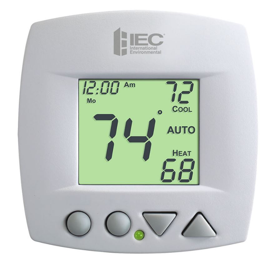
Glossary of Terms
- Auto-Changeover: A mode in which the thermostat will turn on the heating or cooling based on room temperature demand.
- Cool Setpoint: The warmest temperature that the space should rise to before cooling is turned on (without regard to deadband).
- Deadband: The number of degrees the thermostat will wait, once a setpoint has been reached, before energizing heating or cooling.
- Differential: The forced temperature difference between the heat setpoint and the cool setpoint.
- Heat Setpoint: The coolest temperature that the space should drop to before heating is turned on (without regard to deadband).
- Icon: The word or symbol that appears on the thermostat display.
- Mode: The current operating condition of the thermostat (i.e. Off, Heat, Cool, Auto, Program On).
- Non-Programmable Thermostat: A thermostat that does not have the capability of running Time Period Programming.
- Programmable Thermostat: A thermostat that has the capability of running Time Period Programming.
- Pre-Occupancy Purge: Fan operation prior to Occupied 1.
- Temperature Swing: Same as Deadband.
- Time Period Programming: A program that allows the thermostat to automatically adjust the heat setpoint and/or the cool setpoint based on the time of the day.
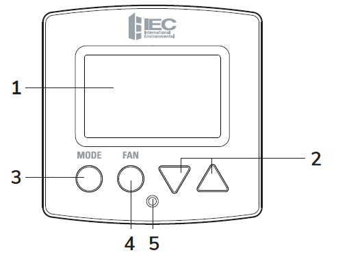
Front Panel
- Backlit Display
- Up, Down Buttons
- Mode Button
- Fan Button
- Heat or Cool Indicator
- Heat = Red, Cool = Green
The Thermostat Backplate
To remove the thermostat backplate: Gently separate the display from the base by pulling from the center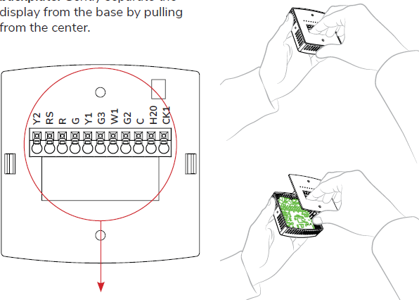
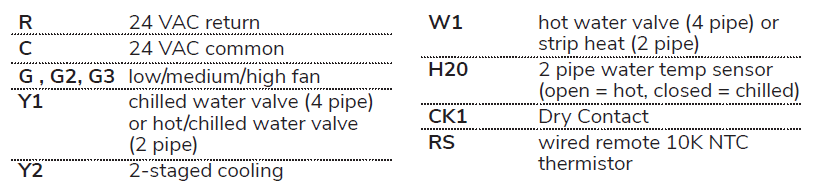
Wiring Diagram
4-Pipe, Low Voltage Valves, Duct Temperature Sensor & Dry Contact
4-Pipe, Low Voltage Valves, Dehumidification Duct, Temperature Sensor and Dry Contact

2-Pipe, Low Voltage Valves, H2O Changeover Sensor

Connect to Wi-Fi
- Wi-Fi Setup
- The IEC Configurator App is needed to configure the Wi-Fi Settings of this thermostat.
- Download the IEC Configurator App
- from your mobile device’s App Store.
- Open the IEC Configurator App
- Choose the thermostat by sliding the thermostat pictures at the top of the apps’ display to the left until you see a picture of the thermostat.
- Press and hold the FAN button of the thermostat for approximately 5 seconds to enter Wi-Fi setup screens.
- Press the DOWN button to setup Wi-Fi.
- Follow the instructions that appear on the IEC Configurator App.
Connect to Skyport
The steps below illustrate account creation from a browser. To create a Skyport account, a thermostat must be joined to the account. If the thermostat is connected to the local Wi-Fi Access Point, but you do not have a Skyport account, you may create an account and join the thermostat to the account by doing the following:
- Open your browser to: http://IEC.skyportcloud.com
- Select “Create account now”

- Follow on screen instructions to create an account and add a thermostat to the Skyport account
Join a Thermostat to Skyport
If the thermostat is connected to the local Wi-Fi access point but not yet joined to an existing Skyport account, you may join the thermostat to the account by doing the following:
- Log in to your Skyport account.
- Select the “Location” you want to add a thermostat into.
- Select the “Thermostat tab”.
- Select “+ Add thermostat”. A screen will ‘pop-up’ asking for a six digit code.
- Press the FAN button on the thermostat for 5 seconds.
- Press the UP button on the thermostat.
- A six digit code will appear on the thermostat’s display.
- Enter the six digit code into your Skyport account
Wi-Fi Status Screens
Press and hold the FAN button on the thermostat for 5 seconds. When “Wi-Fi Setup” appears on the display, press the MODE button. Pressing the UP or DOWN button will sequence through the following information:
- AP Name
- AP Signal Strength
- IP Address
- MAC Address
- Skyport Status
- API Status
Display Legend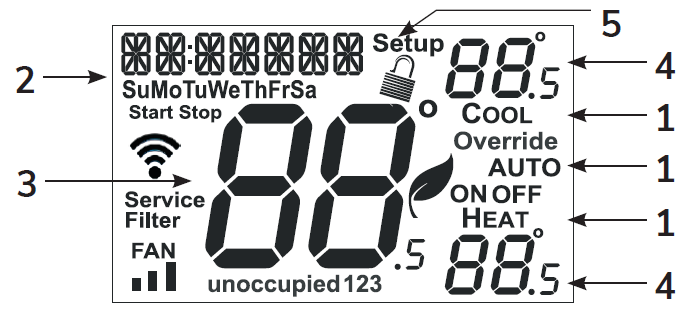
- Mode Indicators
- Selects the operational mode of the equipment.
- HEAT – Indicates the heating mode.
- COOL – Indicates the cooling mode.
- AUTO – Indicates the system will automatically changeover between heat and cool modes as the temperature varies.
- OFF – Indicates heating and cooling are turned off.
- Selects the operational mode of the equipment.
- Clock with Day of the Week
- Indicates the current time and day. This clock is also used to program the time period schedules.
- Room Temperature Display
- Indicates current room temperature.
- Desired Set Temperature
- Indicates desired room temperature(s).
- Setup Icon
- Indicates the thermostat is in the setup mode
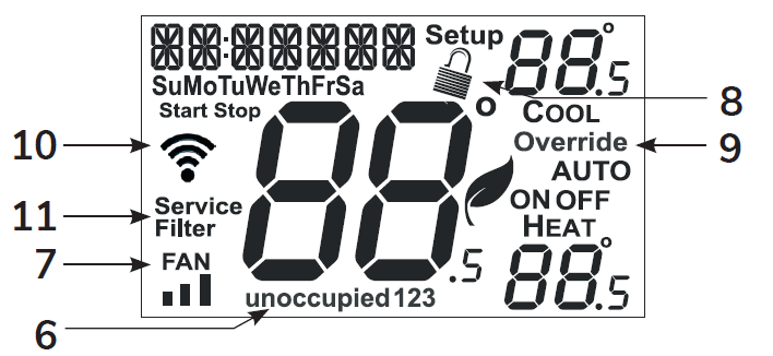
- Indicates the thermostat is in the setup mode
- Occupied and Unoccupied Icons
- Indicates the part of the time period program.
- Fan Icon
- When FAN and any fan speed bars is on, the fan is in manual speed. If the FAN is not on the display, then the FAN is in AUTO mode and will run only when necessary to heat or cool.
- Locked Icon
- Indicates the thermostat’s control buttons have been locked.
- Override Icon
- Indicates OVERRIDE is enabled.
- Wi-Fi Symbol Legend
 When only the ‘dot’ of the Wi-Fi symbol appears = not connected to an access point.
 When the full Wi-Fi symbol appears = connected to an access point.
 When the full Wi-Fi symbol appears and the ‘dot’ of the symbol is flashing = connected to Skyport.
- Service Filter
- Indicates it is time to service your filter
Basic Operation
Auto-Changeover Mode
Pressing the UP or DOWN buttons in AUTO mode will adjust both the heat and cool setpoints simultaneously. To adjust the heat and cool setpoints individually, choose HEAT mode to adjust the heat setpoint, and COOL mode to adjust the cool setpoint, then return to AUTO mode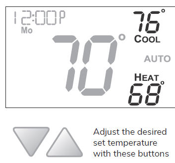
Heat or Cool Mode
Pressing the UP or DOWN buttons in HEAT or COOL mode will adjust only the heat or cool set temperature.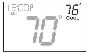
Using the FAN Button
Pressing the FAN button will run the fan in low, medium, or high speed continuously. If the FAN is not on the display, then the fan is in AUTO mode and will run only when necessary to heat or cool
Using the FAN button for FAN Operation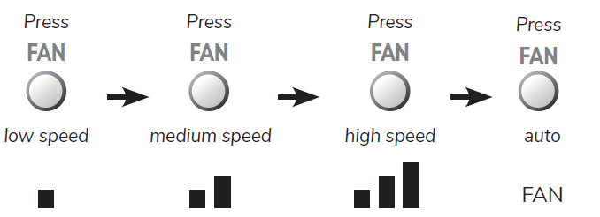
Using the FAN button for OVERRIDE Operation
Note: Override operation may ony be used when the thermostat is running a time period schedule/program.
Unoccupied Operation
During programmed, unoccupied periods pressing and holding the FAN button for more than 5 seconds will force the thermostat into occupied 1 settings for 1 to 4 hours (Setup Step #16, page 19). The OVERRIDE icon will be illuminated during this time. If you press and hold the FAN button while the thermostat is currently overriding the daily schedule, this will reset the timer, returning the thermostat to the correct time period program for the day.
Occupied Operation
Pressing and holding the FAN button for 5 seconds during a programmed Occupied time period will not function as override but will enter the wifi setup section.
User Setup
Table for button presses that are required for entering various menus
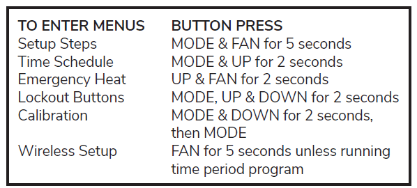
How to Change Settings in the Setup Screens
To enter the setup screens, press the MODE button, and simultaneously press FAN button for 5 seconds. Release the buttons when you see “Setup” on the display. Use the UP or DOWN buttons to adjust the value of your selection. Press MODE to advance to the next setup step. Press MODE and FAN together again to leave the setup screens.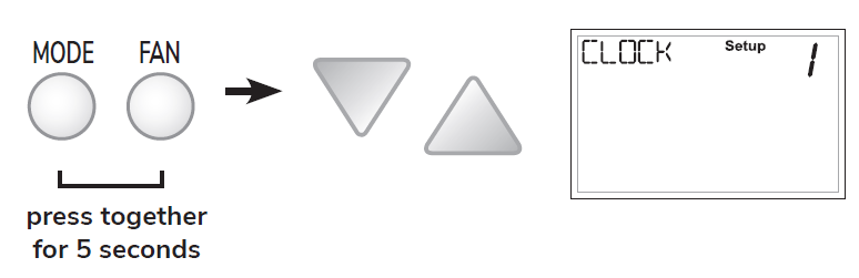
User Setup
Clock
Setting the Clock and Day (setup steps 1 & 2)
Note: When your thermostat is connected to Skyport Cloud Services, the time and day of the week are controlled by Skyport. There is no local adjustment, Skyport also adjusts the time for Daylight Savings Time as well. Setup steps 1 and 2 will not appear on thermostat if connected to Skyport. To set the time and day when not connected to Skyport; enter the setup screens by pressing the MODE button and simultaneously pressing the FAN button for 5 seconds.
Setup step 1 adjusts the clock.
Use the UP and DOWN buttons to adjust the time. Press the MODE button to advance to step 2. Select the day of the week using the UP and DOWN buttons. 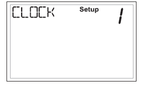 Leave the setup screens by again pressing the MODE button and simultaneously pressing the FAN button for 5 seconds.
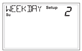
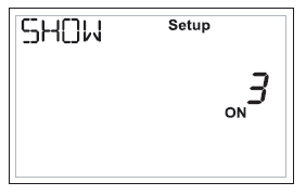
Show Clock (setup step 3)
This setup step will allow for removal of the clock and day of the week from the display. OFF removes the time and day from the display.
Backlight Operation
Programmable (setup step 4)
When the very simplest operation is desired, this thermostat may be configured to be nonprogrammable, with or without Auto-Changeover.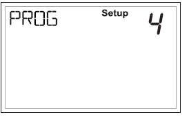
If “OFF” is selected, the thermostat will lockout the Program On screen; only the Off, Heat, Cool and Auto screens may be accessed by pressing the MODE button.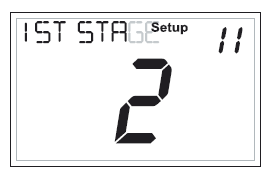 Select “ON” if you would like your thermostat to be programmable, then the PROGRAM mode will be accessible through the use of the MODE button.
Backlight (setup steps 5-8)
- OFF – Backlight turns on only with a button press and turns off after 8 seconds.
- ON – Backlight is on continuously.
- Night Light (setup step 6)
- Selecting ON allows for turning off the backlight of the display during specific times of the day, usually at night.
- Night Light Start Time (setup step 7)
- 12:00 am to 12:00 am
- Night Light Stop Time (setup step 8)
- 12:00 am to 12:00 am
Installer Setup: Pipe Settings
2 or 4 Pipe System (setup step 9)
Select Fan Coil System type:
- 2 Pipe Fan Coil System, or
- 4 pipe Fan Coil System.
2 Pipe System Operation (setup step 10)
Setup Step 10 only appears if Setup Step 9 = 2 pipe
- Heat Only System
- Cool Only System
- Heat/Cool Auto Lockout Aux heat when hot H20 is available
- Heat/Cool Auto, total electric, no Hot H20
- Heat/Cool Auto Changeover System
Installer Setup: Deadband
Deadband
The Deadband is the number of degrees or minutes that the thermostat waits before it initiates the stages of heating or cooling.
1st Stage Deadband (setup step 11)
Specifies the temperature difference between the room temperature and the desired setpoint before the first stage of heating or cooling is allowed to turn on. (1 – 6 degrees) For example, if the heat setpoint is 68˚ and the 1st Stage deadband is set to 2 degrees, the room temperature will need to reach 66˚ before the heat turns on. For additional information on deadband, go to page 25.
Minimum Heat/Cool Setpoint Difference (setup step 12)
This feature allows the user to set the minimum gap between Heat and Cool setpoints in AUTO mode. Select from 0 to 6 degrees
Installer Setup: Setpoint Limits & Lock MODE
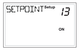
Setpoint Limits (setup step 13)
When this feature is set to ON, the Heat and Cool Setpoints may be restricted to preset levels in Setup Steps 14 and 15.
Maximum Heat Setpoint (setup step 14)
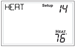 Minimum Cool Setpoint (setup step 15)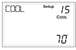
Lock MODE Buttons
This feature is available when the thermostat is connected to Skyport Cloud Services and may only be accessed through Skyport. This security feature is not accessible locally at the thermostat. When this setting is enabled; pressing the MODE button on the thermostat will have no effect. This feature is often used in conjunction with setpoint limits.
Installer Setup
- Maximum Override Time (setup step 16)
- This feature limits the maximum override time when using the OVERRIDE button 1 – 4 hours.
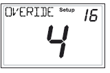
- This feature limits the maximum override time when using the OVERRIDE button 1 – 4 hours.
- Fahrenheit or Celsius (setup step 17)
- This feature allows the thermostat to display temperature in Fahrenheit or Celsius.
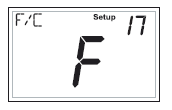
- This feature allows the thermostat to display temperature in Fahrenheit or Celsius.
- Fan Auto Operation (setup step 18)
- ON = Continuous low speed fan
- OFF = Only energize with a heating or cooling cycle
- Fan Relay Type (setup step 19)
- NORMAL = Conventional 3 speed fan coil system
- SPECIAL = IEC Fan Coil using E025-71481103/4 Relay Board
- Wired Sensor Type (setup step 20)
- RETURN, OUTDOOR, SUPPLY = the sensor temperature is reported to Skyport to monitor only
- REMOTE = the sensor can be used for temperature control
- Control to Sensor (setup step 21)
- Select LOCAL to control the thermostat temperature with the internal sensor. Select REMOTE to control the temperature with a remote sensor connected to the RS & R terminals of the thermostat backplate.
- Pre-Occupancy Fan Purge (setup step 22)
- When this feature is activated, the fan will turn on during an unoccupied period at a preset amount of time prior to Occupied 1. This preoccupancy fan purge timer may be set from zero to three hours, in 15 minute increments. Zero (0) means this feature is turned off
- When this feature is activated, the fan will turn on during an unoccupied period at a preset amount of time prior to Occupied 1. This preoccupancy fan purge timer may be set from zero to three hours, in 15 minute increments. Zero (0) means this feature is turned off
- Hot Water Valve Type (setup step 23)
- NORMAL CLOSED = Default setting, hot water valve does not allow water flow when unpowered
- NORMAL OPEN = Hot water valve allows water flow when unpowered
- Chilled Water Valve Type (setup step 24)
- NORMAL CLOSED = Default setting, chilled water valve does not allow water flow when unpowered.
- NORMAL OPEN = Chilled water valve allows waterflow when unpowered.
Dry Contact Operation
Dry Contact Polarity (setup step 25)
- Open (Normally Open)
- The dry contact is open until the connected device closes the circuit.
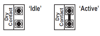
- The dry contact is open until the connected device closes the circuit.
- Closed (Normally Closed)
- The dry contact is closed until the connected device opens the circuit.
- The dry contact is closed until the connected device opens the circuit.
Dry Contact Use (setup step 26)
- Condensate Pan
- If selected when the Dry Contact is active, the thermostat will lockout compressor terminal(s) and “CONDENSATE PAN” will appear on the display.
- Holiday
- If Holiday is selected when the dry contact is active, the thermostat will be forced into HOLIDAY/ Unoccupied settings.
- Occupied
- If Occupied is selected when the dry contact is active, the thermostat will be forced into occupied settings.
- Skyport Cloud Services (setup step 27)
- If set to ON, the thermostat may communicate and receive data from the Skyport Cloud Services.
- Local API (setup step 28)
- Turning on the local API allows 3rd party software to interface with the thermostat such as a home automation system.
- Time API (setup step 29)
- Only appears when prior step for Local API is set to ON. This step allows the internal clock to be altered using the API.
Locking/Unlocking the Keypad
To prevent unauthorized use of the thermostat, the front panel buttons may be disabled. To disable, or ‘lock’ the keypad, press and hold the MODE button. While holding the MODE button, press the UP and DOWN buttons together, for two seconds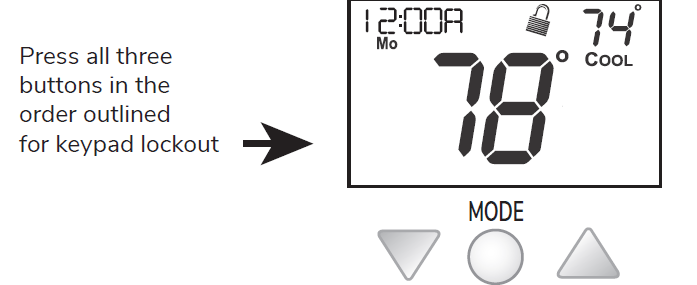
Programming a Daily Schedule
To enter Time Period Programming screens, Press and hold MODE and UP until the scrolling prompt appears. Press MODE to continue to next step.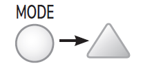
- Select the number of Occupied time periods – Press the UP or DOWN buttons to choose the maximum number (up to 3 maximum) of Occupied time periods in a day.
- Select the Mode for the Occupied period – Press the UP or DOWN buttons to choose the mode for the occupied period. The choices are: Off, Heat only, Cool only and AUTO changeover.
- Adjust the Occupied Cool Setpoint – Press the UP or DOWN buttons to adjust the Cooling setpoint for comfort.
- Adjust the Occupied Heat Setpoint – Press the UP or DOWN buttons to adjust the Heating setpoint for comfort.
- Set the Unoccupied Mode – Press the UP or DOWN buttons to choose the mode for the Unoccupied period. The thermostat is in Unoccupied when the Time Period Schedule is running and there is not an active Occupied period. The choices are: Off, Heat only, Cool only and AUTO changeover.
- Adjust the Unoccupied Cool Setpoint – Press the UP or DOWN buttons to adjust the Cooling setpoint for times when the thermostat is in Unoccupied
Adjust the Unoccupied Heat Setpoint – Press the UP or DOWN button to adjust the Heating setpoint for times when the thermostat is in Unoccupied.
The following steps determine when the Occupied period(s) will be active.
- Enable Occupied 1 – Press the UP or DOWN button to enable (On) or to disable (Off) Occupied 1 on Monday.
- Adjust the Start Time for Occupied 1 – Press the UP or DOWN button to adjust the start time for Occupied 1 on Monday.
Upon pressing MODE after the above step; you will be prompted to Save and Exit or Copy this Occupied schedule to another day.
- To save and exit – Press the MODE and UP button.
- To Copy Monday’s settings/schedule to Tuesday – Press Up and then MODE. Press MODE again to copy the Monday Settings/ schedule to subsequent days.
- B Press MODE and then press the UP/ DOWN button to select the day to program. Repeat the above steps for each day you would like to program
About Advanced Features & Operation
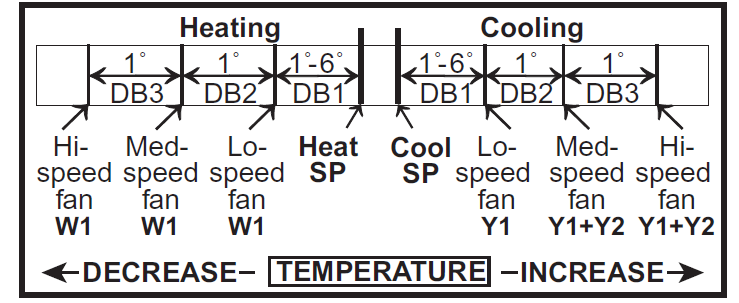
- DEADBAND OPERATION – Controls one Heat and one Cool stage with a three-speed fan (see below).
- The low speed fan for heat or cool is turned on when: The temperature spread from the setpoint is equal to or greater than: the setpoint plus the 1st stage deadband (Setup Step 11, page 17). This 1st stage deadband is adjustable from 1-6 degrees and the default is two degrees.
- The medium speed fan for heat or cool is turned on when: The temperature spread from the setpoint is equal to or greater than: the setpoint plus the 1st stage deadband (Setup Step 11, page 17), plus the 2nd stage deadband. This 2nd stage deadband is fixed at one degree and is not adjustable.
- The high speed fan for heat or cool is turned on when: The temperature spread from the setpoint is equal to or greater than: the setpoint plus the 1st stage deadband (Setup Step 11, page 17), plus the 2nd stage deadband, plus the 3rd stage deadband. This 3rd stage deadband is fixed at one degree and is not adjustable.
Operation: Calibration
Calibration
Under normal circumstances, it will not be necessary to adjust the calibration of the temperature sensor. If calibration is required, please contact a trained HVAC technician to correctly perform the following procedure.
Operation: Factory Defaults
Factory Defaults
If, for any reason, you desire to return all the stored settings back to the factory default settings, follow the instructions below.
WARNING: This will reset all Time Period and Advanced Programming to the default settings. Any information entered prior to this reset will be permanently lost
 Place the thermostat in the OFF mode.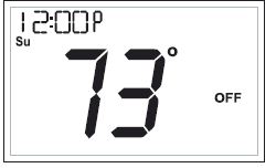
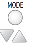
 Press and hold the MODE button. While holding the MODE button, press and hold the DOWN button for 5 seconds. All icons will appear on the display.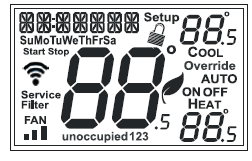
 After calibration is complete, press the MODE button once to save your changes and return to normal operation.
If, for any reason, you desire to return all the stored settings back to the factory default settings, follow the instructions below.
- A. After all of the icons appear, release the MODE and DOWN buttons.
- B. Press and hold the FAN button for 2 seconds. Fd (Factory default settings) and ALL will appear on the display
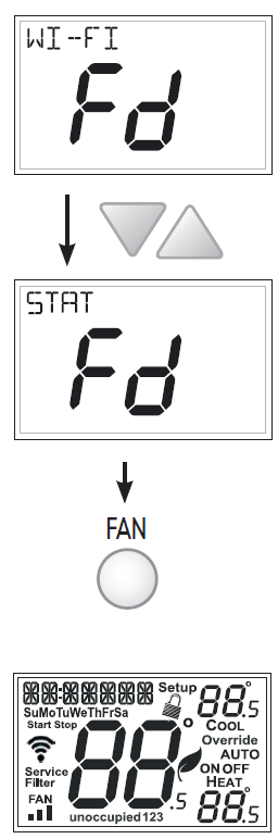
- You now have the option of restoring the factory settings to just Wi-Fi (Wi- Fi), or just the thermostat (STAT), or both the thermostat and Wi-Fi (ALL).
- C. Select one of the above options using the Up or Down buttons.
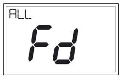
- D. Press FAN for 2 seconds to restore the factory settings. After factory settings are restored, the thermostat display will return to the “all icon” screen.
Advanced Setup Table
| Step # | Description | Pg # | Range | FD |
| 1
2 3 4 5 6 7 8 9 10
11 12
13 14 15 16 17 18 19 20 21 22 23 24 25 26
27 28 29 |
CLOCK WEEKDAY SHOW CLOCK PROG BACKLIGHT NIGHTLT NIGHTLT START NIGHTLT STOP
NUMBER OF WATER PIPES 2 PIPE SUBMODE (only if prior step=2)
1ST STAGE DEADBAND MINIMUM HEAT/COOL SPREAD (unless 2 pipe single mode) SETPOINT LIMITS MAX HEAT SETPOINT MIN COOL SETPOINT MAX OVRRIDE TIME IN HOURS DISPLAY F/C CONTINUOUS FAN, ON (low) or OFF (auto) FAN TYPE, ON (IEC) or OFF WIRED SENSOR TYPE CONTROL TO TEMP SOURCE PRE-OCC FAN PURGE TIME HOT WATER VALVE TYPE CHILLED WATER VALVE TYPE DRY CONTACT POLARITY DRY CONTACT USE
SKYPORT API TIME API |
14
14 14 15 15 15 15 15 16 16
17 17
18 18 18 19 19 19 19 19 20 20 21 21 22 22
23 23 23 |
12A – 12A
Monday – Sunday On, Off On, Off On, Off On, Off 12A – 12A 12A – 12A 4 PIPE, 2 PIPE Heat only, Cool Only Auto Change, Total Elec Auto Change, Aux Heat Auto Change
1 – 6 degrees 0 – 6 degrees
On, Off 35 – 99 degrees 35 – 99 degrees 0 – 4 hrs F, C On, Off On, Off control, monitor thermostat, sensor off – 3 hrs n.o / n.c. n.o / n.c. n.o / n.c. occupied, condensate, fdd, holiday On, Off On, Off On, Off |
12P
Monday On On Off Off 8:00P 6:00A 4 PIPE Auto Change
2 2
Off 82 66 4 F Off Off control thermostat off n.c. n.c. n.c. condensate
On Off Off
|
Terms and Conditions
- Orders shall not be binding upon International Environmental Corporation, an Oklahoma corporation (hereinafter referred to as “IEC”) unless accepted by an authorized representative of IEC at its office in Oklahoma City, Oklahoma. No distributor, sales representative or any other person or entity (except authorized employees of IEC at its office in Oklahoma City, Oklahoma) has any authority whatsoever to bind IEC to any representation or agreement of any kind.
- IEC does not build items to plans and specifications. IEC agrees to furnish only the items as described in IEC’s acknowledgment unless IEC’s office in Oklahoma City, Oklahoma has previously received and accepted, in writing, approved submittals from Purchaser.
- Prices acknowledged are firm only if Purchaser releases the goods covered by this order for immediate production by IEC within sixty (60) days from the date of Purchaser’s initial offer to purchase and for shipment by IEC within IEC’s estimated shipping date, unless otherwise agreed to in writing by IEC at its office in Oklahoma City, Oklahoma. If Purchaser does not meet the terms and conditions of this paragraph, the prices are subject to escalation to those prices in effect at time of shipment without notice to Purchaser.
- All prices are F.O.B. IEC’s factory, unless otherwise agreed by IEC in writing; and, all payments and prices shall be in U.S.A. dollars.
- If goods are released for production but IEC is prevented by the Purchaser from shipping upon completion or by IEC’s estimated shipping date, whichever is later, IEC may at its option, in addition to all other remedies, invoice Purchaser to be payable within thirty (30) days and store the goods at Purchaser’s sole expense.
- Title to and risk of loss to the goods passes to the Purchaser F.O.B. IEC’s factory.
- Disclaimer It is expressly understood that unless a statement is specifically identified as a warranty, statements made by IEC or its representatives relating to IEC’s products, whether oral, written or contained in any sales literature, catalog or any other agreement, are not express warranties and do not form a part of the basis of the bargain, but are merely IEC’s opinion or commendation of IEC’s products.
- EXCEPT AS SPECIFICALLY SET FORTH HEREIN, THERE IS NO EXPRESS WARRANTY AS TO ANY OF IEC’S PRODUCTS. IEC MAKES NO WARRANTY AGAINST LATENT DEFECTS IEC MAKES NO WARRANTY OF MERCHANTABILITY OF THE GOODS OR OF THE FITNESS OF THE GOODS FOR ANY PARTICULAR PURPOSE.
- Grant of Limited Express Warranty IEC warrants IEC products purchased and retained in the United States of America and Canada to be free from defects in material and workmanship under normal use and maintenance as follows: (1) All complete fan coil units built or sold by IEC for twelve (12) months from date of unit start up or eighteen (18) months from date of shipment (from factory), whichever comes first. All parts must be returned to IEC’s factory in Oklahoma City, Oklahoma, freight prepaid, no later than sixty (60) days after the date of the failure of the part; if IEC determines the part to be defective and within IEC’s Limited Express Warranty, IEC shall, when such part has been either replaced or repaired, return such to a factory recognized contractor or service organization, F.O.B. IEC’s factory, Oklahoma City, Oklahoma, freight prepaid. The warranty on any parts repaired or replaced under warranty expires at the end of the original warranty period. For information and warranty service contact:
International Environmental Corporation
- Customer Service
- 5000 West I-40
- Oklahoma City, OK 73128
- (405) 605-5000
Warranty
This warranty does not cover and does not apply to: (1) Air filters, fuses, fluids; (2) Products relocated after initial installation; (3) Any portion or component of any system that is not supplied by IEC, regardless of the cause of the failure of such portion or component; (4) Products on which the unit identification tags or labels have been removed or defaced; (5) Products on which payment to IEC is or has been in default; (6) Products which have defects or damage which result from improper installation, wiring, electrical imbalance characteristics or maintenance; or are caused by accident, misuse or abuse, fire, flood, alteration or misapplication of the product; (7) Products which have defects or damage which result from a contaminated or corrosive air or liquid supply or operation at abnormal temperatures; (8) Mold, fungus or bacteria damages; (9) Products subjected to corrosion or abrasion; (10) Products manufactured or supplied by others; (11) Products which have been subjected to misuse, negligence or accidents; (12) Products which have been operated in a manner contrary to IEC’s printed instructions; or (13) Products which have defects, damage or insufficient performance as a result of insufficient or incorrect system design or the improper application of IEC’s products. IEC is not responsible for: (1) The cost of any fluids or other system components, or associated labor to repair or replace the same, which is incurred as a result of a defective part covered by IEC’s Limited Express Warranty; (2) The costs of labor, materials or service incurred in removal of the defective part, or in obtaining and replacing the new or repaired part; or, (3) Transportation costs of the defective part from the installation site to IEC or of the return of any part not covered by IEC’s Limited Express.
Limitation
This Limited Express Warranty is given in lieu of all other warranties. If, notwithstanding the disclaimers contained herein, it is determined that other warranties exist, any such warranties, including without limitation any express warranties or any implied warranties of fitness for particular purpose and merchantability, shall be limited to the duration of the Limited Express Warranty.
Limitation of Remedies
In the event of a breach of the Limited Express Warranty, IEC will only be obligated at IEC’s option to repair the failed part or unit or to furnish a new or rebuilt part or unit in exchange for the part or unit which has failed. If after written notice to IEC’s factory in Oklahoma City, Oklahoma of each defect, malfunction or other failure and a reasonable number of attempts by IEC to correct the defect, malfunction or other failure and the remedy fails of its essential purpose, IEC shall refund the purchase price paid to IEC in exchange for the return of the sold good(s). Said refund shall be the maximum liability of IEC. THIS REMEDY IS THE SOLE AND EXCLUSIVE REMEDY OF THE BUYER OR THEIR PURCHASER AGAINST IEC FOR BREACH OF CONTRACT, FOR BREACH OF ANY WARRANTY OR FOR IEC’S NEGLIGENCE OR IN STRICT LIABILITY.
- Limitation of Liability IEC shall have no liability for any damages if IEC’s performance is delayed for any reason or is prevented to any extent by any event such as, but not limited to: any war, civil unrest, government restrictions or restraints, strikes, or work stoppages, fire, flood, accident, shortages of transportation, fuel, material or labor, acts of God or any other reason beyond the sole control of IEC. IEC
EXPRESSLY DISCLAIMS AND EXCLUDES ANY LIABILITY FOR CONSEQUENTIAL OR INCIDENTAL DAMAGE IN CONTRACT, FOR BREACH OF ANY EXPRESS OR IMPLIED WARRANTY, OR IN TORT, WHETHER FOR IEC’s NEGLIGENCE OR AS STRICT LIABILITY. - IEC shall have no system design, application or maintenance responsibility or responsibility for mold, fungus or bacteria to Purchaser or any other third party.
- All sales, goods and services, use, excise, value-added, transportation, privilege, occupational consumption, storage, document, transaction or other taxes which may be levied by any taxing authority as a result of this transaction shall be paid by the Purchaser.
- Unless otherwise agreed to in writing by IEC any technical data furnished in conjunction with this order and not obtainable from another source shall not be duplicated, used, or disclosed in whole or in part for any purpose other than to evaluate this order.
- IEC shall have no liability or other obligation hereunder, if IEC’s performance is delayed for any reason or is prevented to any extent by any event such as, but not limited to: any act of God, strike or work stoppage, fire, flood, accident, allocation, or other controls of Government authorities, shortages of transportation, fuel, material or labor, or any other cause beyond IEC’s sole control. Any shipping date stated by IEC is IEC’s best estimate but IEC makes no guarantee of shipment by any such date and shall have no liability or other obligation for failure to ship on such date, regardless of cause.
- Payment terms are net thirty (30) days from date of shipment on approved credit. One and one half percent (1 1/2%) per month (18% annual rate) may be charged on past due accounts or the highest rate permitted by applicable law, whichever is lesser. In the event the account is placed for collection, Purchaser shall be responsible for all reasonable attorneys fees or costs on a solicitor and client basis, plus all other costs and expenses incurred by IEC in securing payment.
- Purchaser shall not cancel the contract without prior written consent of an authorized representative of IEC at its offices in Oklahoma City, Oklahoma. In the event Purchaser cancels the contract with the prior written consent of IEC after the Purchaser’s offer to purchase is received and acknowledged in writing, IEC shall be entitled to receive from Purchaser IEC’s cost incurred to time of cancellation plus a reasonable allowance for overhead and profit.
- Purchaser shall not assign any of its interest or rights under this agreement without written consent of IEC.
- IEC will protect all its lien rights. IEC will not furnish lien waivers or releases until IEC receives payment, in full, at its office in Oklahoma City, Oklahoma from Purchaser for the goods covered by this order. There is no authorized retainage for any reason.
- This Agreement shall be construed, and the rights and liabilities of the parties hereunder shall be determined in accordance with the laws of the State of Oklahoma. If it shall be found that any portion of this agreement violates any particular law of the United States or any state in the United States having jurisdiction or, if applicable, any law of Canada or any province or territory in Canada having jurisdiction, such portion of the agreement shall be of no force and effect in that political unit, division or sub-division in which they are illegal or unenforceable and the agreement shall be treated as if such portion or portions had not been inserted. In the event that any dispute or disagreement in connection with any order should arise or exist between Purchaser and IEC, jurisdiction and venue for any legal action shall be, if IEC so elects, exclusively in the state or federal courts in Oklahoma County, Oklahoma. The statute of limitations on any claim of the Purchaser against the IEC shall be one (1) year from the date the cause of action accrues.
- Without regard to any other agreement, all obligations of Purchaser to IEC shall become immediately due and payable if Purchaser becomes insolvent or if Purchaser does not make payments when due or breaches any other agreement or fails to perform any obligation.
- All orders are expressly limited and made conditional upon acceptance by Purchaser of the terms and conditions set forth above without change. There shall be no understandings, agreements, or obligations (outside these terms and conditions) unless specifically set forth in writing and accepted by signature of an authorized representative of IEC in Oklahoma City, Oklahoma.
- The parties hereto have requested that these presents and all judicial proceedings relating thereto be drafted in English.
FCC
FCC Compliance Statement
This equipment has been tested and found to comply with the limits for a Class B digital device, pursuant to part 15 of the FCC Rules. These limits are designed to provide reasonable protection against harmful interference in a residential installation. This equipment generates, uses and can radiate radio frequency energy and, if not installed and used in accordance with the instructions, may cause harmful interference to radio communications. However, there is no guarantee that interference will not occur in a particular installation. If this equipment does cause harmful interference to radio or television reception, which can be determined by turning the equipment off and on, the user is encouraged to try to correct the interference by one or more of the following measures:
- Reorient or relocate the receiving antenna.
- Increase the separation between the equipment and receiver.
- Connect the equipment into an outlet on a circuit different from that of the receiver.
- Consult the dealer or an experienced radio or TV technician for help.
Notice: Only peripherals complying with FCC limits may be attached to this equipment. Operation with noncompliant peripherals or peripherals not recommended by IEC, is likely to result in interference to radio and TV reception. Changes or modifications to the product, not expressly approved by IEC could void the user’s authority to operate the equipment.
FCC – INDOOR Mobile Radio Information: To comply with FCC/IC RF exposure limits for general population / uncontrolled exposure, the antenna(s) used for this transmitter must be installed to provide a separation distance of at least 20 cm from all persons and must not be co-located or operating in conjunction with any other antenna or transmitter.
This Device complies with Industry Canada License-exempt RSS standard(s). Operation is subject to the following two conditions:
- this device may not cause interference, and
- this device must accept any interference, including interference that may cause undesired operation of the device.
IEC
- 5000 W. 1-40 Service Rd.
- Oklahoma City, OK 73128
- P: 405.605.5000
- F: 405.605.5001
- www.iec-okc.com
Reference
Download Manual:
IEC E055-71520325 Programmable Fan Coil Thermostat Owners Manual
OTHER MANUALS
IEC E055-71520325 Programmable Fan Coil Thermostat User Manual
IEC E055-71520325 Programmable Fan Coil Thermostat Product Specifications Guide

IEC E055-71520325 Programmable Fan Coil Thermostat Owners Manual