Honeywell Home T6 Pro Programmable Thermostat

Package Includes
- T6 Pro Thermostat
- UWP™ Mounting System
- Decorative Cover Plate
- Screws and Anchors
- 2 AA Batteries
- Thermostat Literature
Optional Cover Plate Installation

NOTE: If an Optional Cover Plate is not required, see “UWP Mounting System installation” on the next page. Use the Optional Cover Plate when you need to cover the paint gap from the old thermostat. There are different cover plates depending on when the thermostat was manufactured. For the square cover plate:
- Separate the Cover Plate from Mounting Plate.
- Mount the Mounting Plate onto the wall using any of the 8 screw holes. Insert and tighten the mounting screws supplied with Cover Plate Kit. Do not overtighten. See Figure 2. Make sure the Mounting Plate is level.
- Attach the UWP by hanging it on the top hook of the Mounting Plate and then snapping the bottom of the UWP in place. See Figure 3.
- Snap the Cover Plate onto the Mounting Plate. See Figure 4.
For the rectangular cover plate
- Mount the Cover Plate on the wall using any of the 6 screw holes. Insert and tighten the mounting screws supplied with the Cover Plate. Do not over-tighten. See Figure
- Make sure the Cover Plate is level. Attach the UWP by hanging it on the top hook of the Cover Plate and then snapping the bottom of the UWP in place. See Figure 2.
- If there are no existing wall anchors:
- Position the Cover Plate on the wall. Level and mark hole positions. See Figure 1.
- Drill holes at marked positions, and then lightly tap supplied wall anchors into the wall using a hammer.
- If your box contains red anchors, drill 7/32” (5.6 mm) holes.
- If your box contains yellow anchors, drill 3/16” (4.8 mm) holes.
- Use 2x supplied screws (#8 1-1/2” (38 mm) for red anchors and # 1- 1/2” (38 mm) for yellow anchors).
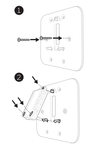
UWP Mounting System Installation

- Before starting, turn the power off at the breaker box or switch. Open the package to find the UWP. See Figure 1.
- Position the UWP on the wall. Level and mark hole positions. See Figure 2. Drill holes at marked positions, and then lightly tap supplied wall anchors into the wall using a hammer.
- If your box contains red anchors, drill 7/32” holes.
- If your box contains yellow anchors, drill 3/16” holes.
- Pull the door open and insert the wires through the wiring hole of the UWP. See Figure 3.
- Place the UWP over the wall anchors. Insert and tighten mounting screws supplied with the UWP. Do not over-tighten. Tighten until the UWP no longer moves. Close the door. See Figure 4.
Power options

Setting Slider Tabs

Set R Slider Tab

- Use a built-in jumper (R Slider Tab) to differentiate between one or two transformer systems.
- If there is only one R wire, and it is connected to the R, Rc, or RH terminal, set the slider to the up position (1 wire).
- If there is one wire connected to the R terminal and one wire connected to the Rc terminal, set the slider to the down position (2 wires).
NOTE: Slider Tabs for U terminals should be left in place for T6 Pro models.
Wiring terminal designations

The terminal can be jumped using Slider Tab. See “Setting Slider Tabs” above.

Note: Not all terminals may be used, depending on the system type that is being wired. The most commonly used terminals are shaded.
Wiring conventional systems: forced air and Hydronics
Shaded areas below apply only to TH6320U/TH6220U or as otherwise noted.
1H/1C System (1 transformer)
- R Power [1]
- Rc [R+Rc joined by Slider Tab] [2]
- Y Compressor contactor
- C 24VAC common [3]
- W Heat
- G Fan
Heat-only System
- R Power [1]
- Rc [R+Rc joined by Slider Tab] [2]
- C 24VAC common [3]
- W Heat
Heat-only System (Series 20) [5]
- R Series 20 valve terminal “R” [1]
- Rc [R+Rc joined by Slider Tab] [2]
- Y Series 20 valve terminal “W”
- C 24VAC common [3]
- W Series 20 valve terminal “B”
Heat-only System
(power open zone valve) [5]
- R Power [1]
- Rc [R+Rc joined by Slider Tab] [2]
- W Valve
- C 24VAC common [3]
1H/1C System (2 transformers)
- R Power (heating transformer) [1]
- Rc Power (cooling transformer) [1]
- Y Compressor contactor
- C 24VAC common [3, 4]
- W Heat
- G Fan
Heat-only System with Fan
- R Power [1]
- Rc [R+Rc joined by Slider Tab] [2]
- C 24VAC common [3]
- W Heat
- G Fan
Cool-only System
- R Power [1]
- Rc [R+Rc joined by Slider Tab] [2]
- Y Compressor contactor
- C 24VAC common [3]
- G Fan
2H/2C System (1 transformer) [6]
- R Power [1]
- Rc [R+Rc joined by Slider Tab] [2]
- Y Compressor contactor (stage 1)
- C 24VAC common [3]
- W Heat (stage 1)
- G Fan
- W2 Heat (stage 2)
- Y2 Compressor contactor (stage 2)
NOTES
Wire specifications: Use 18- to 22-gauge thermostat wire. A shielded cable is not required.
- Power supply. Provide disconnect means and overload protection as required.
- Move R-Slider Tab on UWP to the R setting. For more information, see “Setting Slider Tabs” on page 3
- Optional 24VAC common connection.
- The common connection must come from the cooling transformer.
- In ISU set the Heat system type to Radiant Heat. Set the number of cool stages to 0.
- In Installer Setup, set the system type to 2Heat/2Cool Conventional.
Wiring heat pump systems
Shaded areas below apply only to TH6320U/TH6220U or as otherwise noted.
1H/1C Heat Pump System
- R Power [1]
- Rc [R+Rc joined by Slider Tab] [2]
- Y Compressor contactor
- C 24VAC common [3]
- O/B Changeover valve [7]
- G Fan
- W Do not use this terminal for heat pump applications!
2H/1C Heat Pump System [8]
- R Power [1]
- Rc [R+Rc joined by Slider Tab] [2]
- Y Compressor contactor
- C 24VAC common [3]
- O/B Changeover valve [7]
- G Fan
- Aux Auxiliary heat
- E Emergency heat
- L Heat pump fault input
- W Do not use this terminal for heat pump applications!
2H/2C Heat Pump System
(TH6320U only) [9]
- R Power [1]
- Rc [R+Rc joined by Slider Tab] [2]
- Y Compressor contactor (stage 1)
- C 24VAC common [3]
- O/B Changeover valve [7]
- G Fan
- Y2 Compressor contactor (stage 2)
- L Heat pump fault input
- W Do not use this terminal for heat pump applications!
3H/2C Heat Pump System
(TH6320U only) [10]
- R Power [1]
- Rc [R+Rc joined by Slider Tab] [2]
- Y Compressor contactor (stage 1)
- C 24VAC common [3]
- O/B Changeover valve [7]
- G Fan
- Aux Auxiliary heat
- E Emergency heat
- Y2 Compressor contactor (stage 2)
- L Heat pump fault input
- W Do not use this terminal for heat pump applications!
Dual Fuel System (TH6320U / TH6220U only)
- R Power [1]
- Rc [R+Rc joined by Slider Tab] [2]
- Y Compressor contactor (stage 1)
- C 24VAC common [3]
- O/B Changeover valve [7]
- G Fan
- Aux Auxiliary heat
- E Emergency heat
- Y2 Compressor contactor (stage 2 – if
- needed) [11]
- L Heat pump fault input
- S Outdoor sensor
- S Outdoor sensor
- W Do not use this terminal for heat pump applications!
NOTES
Wire specifications: Use 18- to 22-gauge thermostat wire. A shielded cable is not required.
- Power supply. Provide disconnect means and overload protection as required.
- Move R-Slider Tab on UWP to the R setting. For more information, see “Setting Slider Tabs” on page 3
- Optional 24VAC common connection.
- In Installer Setup, set the system type to 2Heat/2Cool Conventional.
- In Installer Setup, set the changeover valve to O (for cool changeover) or B (for heat changeover).
- In ISU set the Heat system type to the Heat pump. 1 compressor and 1 stage of backup heat.
- In ISU set the Heat system type to the Heat pump. 2 compressors and 0 stages of backup heat.
- In ISU set the Heat system type to the Heat pump. 2 compressors and 1 stage of backup heat.
- Dual fuel with Y2 only for TH6320U
Thermostat mounting

- Push excess wire back into the wall opening.
- Close the UWP door. It should remain closed without bulging.
- Align the UWP with the thermostat, and push gently until the thermostat snaps in place.
- Turn the power on at the breaker box or switch.
Set the time and date
Time

- Press Menu on your thermostat.
- Press
 or
or  go to TIME. Press Select.
 - Press or choose between 12 or 24 hours. Press Select.
- Use or adjust the hour. Press Select.
- Use or adjust the minutes. Press Select to exit the Time menu.
Date
- If previously setting time, continue to Step If at the Home screen, press Menu on your thermostat.
- Press or go to DATE. Press Select.
- Use or adjust the year. Press Select.
- use the or to adjust month. Press Select.
- use the or to adjust day. Press Select to save and exit the Date menu.
System operation settings

- Press the Mode button to cycle to the next available System mode.
- Cycle through the modes until the required System mode is displayed and leave it to activate.
NOTE: Available System modes vary by model and system settings.
System modes:
- Auto
- Heat
- Cool
- Em Heat
- Off
Fan operation settings
- Press the Fan button to cycle to the next available Fan mode.
- Cycle through the modes until the required Fan mode is displayed and leave it to activate.
NOTE: Available Fan modes vary with system settings.
Fan modes:- Auto: The fan runs only when the heating or cooling system is on.
- On Fan is always on.
- Circ: The fan runs randomly about 33% of the time.
Alerts or Reminders

- Press Menu, and then press until the display shows ALRT.
- Press Select to display which alert(s) are present.
- The word SNZE (SNOOZE) appears.
- Press Select again to snooze the reminder for 7 days.
- To clear the alert, press Select, and then press goes to CLER (Clear).
- Press Select to clear the reminder. Some alerts cannot be snoozed or cleared. Please call your local heating and cooling professional if this occurs. The heating and cooling system may require service.
Installer setup (ISU)

- Press and hold the CENTER and buttons for approximately 3 seconds to enter the advanced menu.
- Press Select to enter ISU.
- Press Select to cycle through menu setup options.
- Press or change values or select from available options.
- Press Select and confirm your settings or press Back to ignore changes and return to the ISU menu screen to continue editing another setup option.
- To finish the setup process and save your setting, press Home and return to the Home screen.
NOTE: A complete list of all setup (ISU) parameters and options start below and continues through page 10.
Advanced setup options (ISU)
NOTE: Depending on system settings, not all options may be available.
| # ISU | ISU Name | ISU Options (factory default in bold) |
| 120 | Scheduling Options | 0 = Non-Programmable
2 = 5-2 Programmable 3 = 5-1-1 Programmable 4 = 7-Day Programmable |
| 125 | Temperature Indication Scale | 0 = Fahrenheit
1 = Celsius |
| 130 | Outdoor Sensor
(TH6320U / TH6220U only) |
0 = None
1 = Wired Outdoor Sensor |
| 200 | Heating System Type | 1 = Conventional Forced Air Heat
2 = Heat Pump 3 = Radiant Heat 5 = None (Cool Only) |
| 205 | Heating Equipment Type | Conventional Forced Air Heat:
1 = Standard Efficiency Gas Forced Air 2 = High Efficiency Gas Forced Air 3 = Oil Forced Air 4 = Electric Forced Air 5 = Hot Water Fan Coil Heat Pump: 7 = Air to Air Heat Pump 8 = Geothermal Heat Pump Radiant Heat: 9 = Hot Water Radiant Heat 12 = Steam |
| 218 | Reversing Valve O/B | 0 = O (O/B in Cool)
1 = B (O/B in Heat) |
| 220 | Cool Stages / Compressor Stages 200=Conv / 200=HP | 0, 1, 2
Note: Only 1 compressor stage available on TH6210U model. Only 1 compressor stage available on TH6220U model if configured for heat pump. |
| # ISU | ISU Name | ISU Options (factory default in bold) | |
| 221 | Heat Stages / Backup Heat Stages | Heat Stages: 1, 2
Backup Heat Stages: 0, 1 |
|
| 230 | Fan Control in Heat | 1 = Equipment Controls Fan
2 = Thermostat Controls Fan |
|
| 253 | Aux/E terminal control (Fixed to “0” setting on all models except TH6320U) | 0 = Drive both Aux & E together
1 = Aux and E independent |
|
| 255 | Backup Heat Source (Heat Pump Only)
(TH6320U / TH6220U only) |
1 = Electric Forced Air
2 = Gas/Oil Forced Air (or Fossil Forced Air) |
|
| 256 | Emergency Heat Source (TH6320U only) | 1 = Electric Forced Air
2 = Gas/Oil Forced Air (or Fossil Forced Air) |
|
| 260 | External Fossil Fuel Kit
(TH6320U / TH6220U only) |
0 = Thermostat Controls Backup Heat
1 = External Fossil Fuel Kit Controls Backup Heat |
|
| 300 | System Changeover | 0 = Manual
1 = Automatic |
|
| 303 | Auto Changeover Differential | 0 °F to 5 °F
0.0 °C to 2.5 °C Note: Differential is NOT deadband. Resideo uses an advanced algorithm that fixes deadband at 0 °F. The differential setting is the minimum number of degrees from set-point needed to switch from the last mode running (heat or cool) to the opposite mode when the thermostat is in auto-changeover. This is more advanced than previous thermostats. |
|
| 340 | Backup Heat Droop | 0 = Comfort
2 = 2 °F 3 = 3 °F 4 = 4 °F 5 = 5 °F 6 = 6 °F 7 = 7 °F 8 = 8 °F |
9 = 9 °F
10 = 10 °F 11 = 11 °F 12 = 12 °F 13 = 13 °F 14 = 14 °F 15 = 15 °F |
| Note: 0 (comfort) setting only available if backup heat (ISU 255) is set to electric. | |||
| 350 | Upstage Timer for Backup Heat | 0 = Off
1 = 30 minutes 2 = 45 minutes 3 = 60 minutes 4 = 75 minutes 5 = 90 minutes 6 = 2 hours 7 = 3 hours |
8 = 4 hours
9 = 5 hours 10 = 6 hours 11 = 8 hours 12 = 10 hours 13 = 12 hours 14 = 14 hours 16 = 16 hours |
| 355 | Compressor Lockout / Balance Point | — = Off
5 °F to 60 °F (in 5 °F increments) -15.0 °C to 15.5 °C (in 2.5 °C or 3.0 °C increments) Note: Use a wired sensor to set compressor lockout / balance point on TH6320U / TH6220U. |
|
| 356 | Outdoor Lockout Backup Heat | — = Off
5 °F to 65 °F (in 5 °F increments) -15.0 °C to 18.5 °C (in 2.5 °C or 3.0 °C increments) |
|
| 365 | Compressor Cycle Rate (Stage 1) | 1 – 6 | |
| 366 | Compressor Cycle Rate (Stage 2) | 1 – 6 | |
| 370 | Heating Cycle Rate (Stage 1) | 1 – 12 | |
| 371 | Heating Cycle Rate (Stage 2) | 1 – 12 | |
| 375 | Heating Cycle Rate Auxiliary Heat | 1 – 12 | |
| 378 | Heating Cycle Rate Emergency Heat (TH6320U only) | 1 – 12 | |
| 387 | Compressor Protection | 0 = Off
1 – 5 minutes |
|
| # ISU | ISU Name | ISU Options (factory default in bold) | |
| 425 | Adaptive Intelligent Recovery | 0 = No
1 = Yes Note: Adaptive Intelligent Recovery (AIR) is a comfort setting. Heating or cooling equipment will turn on earlier, ensuring the indoor temperature will match the setpoint at the scheduled time. |
|
| 430 | Minimum Cool Setpoint | 50 °F to 99 °F (50 °F)
10.0 °C to 37.0 °C (10.0 °C) |
|
| 431 | Maximum Heat Setpoint | 40 °F to 90 °F (90 °F)
4.5 °C to 32.0 °C (32.0 °C) |
|
| 435 | Keypad Lockout | Series 0-6 (setting on original T6 models):
0 = None 1 = Partial 2 = Full |
Series 7 (setting current T6 models):
0 = Disabled 1 = Enabled |
| Note: Due to customer feedback this feature was changed. On series 0-6 thermostats, you can lockout the thermostat from the ISU the same as you can from menu lockout.
For series 7 or later, this setting allows the contractor to enable or disable the lockout feature. When disabled, there is no lockout option under menu. |
|||
| 500 | Is Indoor Temperature Sensor WIRED to your system? (TH6320U / TH6220U only) | 0 = No
1 = Yes |
|
| 515 | Indoor Sensor type
(TH6320U / TH6220U only) |
0 = 10k
1 = 20k |
|
| 520 | Which Sensors will be used for TEMPERATURE Control? (Multiple Sensors are Averaged) TH6320U / TH6220U only) | 1 = Thermostat Only 2 = Wired Only
3 = Average |
|
| 702 | Number of Air Filters | 0 – 2 | |
| 711 | Air Filter 1 Replacement Reminder | 0 = Off
1 = 10 Run Time Days 2 = 20 Run Time Days 3 = 30 Run Time Days 4 = 45 Run Time Days 5 = 60 Run Time Days 6 = 90 Run Time Days 7 = 120 Run Time Days 8 = 150 Run Time Days 9 = 30 Calendar Days |
10 = 45 Calendar Days
11 = 60 Calendar Days 12 = 75 Calendar Days 13 = 3 Calendar Months 14 = 4 Calendar Months 15 = 5 Calendar Months 16 = 6 Calendar Months 17 = 9 Calendar Months 18 = 12 Calendar Months 19 = 15 Calendar Months |
| 712 | Air Filter 2 Replacement Reminder | 0 = Off
1 = 10 Run Time Days 2 = 20 Run Time Days 3 = 30 Run Time Days 4 = 45 Run Time Days 5 = 60 Run Time Days 6= 90 Run Time Days 7 = 120 Run Time Days 8 = 150 Run Time Days 9 = 30 Calendar Days |
10 = 45 Calendar Days
11 = 60 Calendar Days 12 = 75 Calendar Days 13 = 3 Calendar Months 14 = 4 Calendar Months 15 = 5 Calendar Months 16 = 6 Calendar Months 17 = 9 Calendar Months 18 = 12 Calendar Months 19 = 15 Calendar Months |
| 1400 | Backlighting | 0 = On Demand
1 = Continuous Note: Common wire needed for continuous. |
|
| 1401 | Backlight brightness | 1 – 5
Note: Only displayed if continuous backlight selected. |
|
| 1410 | Clock Format | 12 / 24 | |
| 1415 | Daylight Saving Time | 0 = Off
1 = On |
|
| 1420 | Temperature Display Offset | -3 to 3F (0)
-1.5 to 1.5C (0) |
|
Installer system test

To perform a System Test:
- Press and hold the CENTER and buttons for approximately 3 seconds to enter the advanced menu.
- Use to go to TEST. Press Select to enter System Test.
- Use to change between Heat, Cool, Fan, Em Heat, or Ver (thermostat version information). Press Select.
- Press to turn stages on one at a time, and press to turn them off.
- Use the Home button to exit the System Test.

Specifications
- Temperature Ranges
Heat: 40 °F to 90 °F (4.5 °C to 32.0 °C)
Cool: 50 °F to 99 °F (10.0 °C to 37.0 °C) - Working Ambient Temperature
32 °F to 120 °F (0 C° to 48.9 °C) - Operating Ambient Temperature
37 °F to 102 °F (2.8 °C to 38.9 °C) - Shipping Temperature
-20 °F to 120 °F (-28.9 °C to 48.9 °C) - Operating Relative Humidity
5% to 90% (non-condensing)
Physical Dimensions in inches (mm) (H x W x D) 4-1/16” H x 4-1/16” W x 1-5/32” D
103.5 mm H x 103.5 mm W x 29 mm D
Electrical Ratings
| Terminal | Voltage (50/60Hz) | Running Current |
| W Heating | 20-30 Vac | 0.02-1.0 A |
| W2 (Aux) Heating | 20-30 Vac | 0.02-1.0 A |
| E Emergency Heat | 20-30 Vac | 0.02-0.5 A |
| Y Compressor Stage 1 | 20-30 Vac | 0.02-1.0 A |
| Y2 Compressor Stage 2 | 20-30 Vac | 0.02-1.0 A |
| G Fan | 20-30 Vac | 0.02-0.5 A |
| O/B Changeover | 20-30 Vac | 0.02-0.5 A |
| L/A Input | 20-30 Vac | 0.02-0.5 A |
Troubleshooting
If you have difficulty with your thermostat, please try the following suggestions. Most problems can be corrected quickly and easily.
| Display is blank | • Check circuit breaker and reset if necessary.
• Make sure power switch for heating & cooling system is on. • Make sure furnace door is closed securely. • Make sure fresh AA alkaline batteries are correctly installed (see page 3). |
| Heating or cooling
system does not respond |
• Press Mode button to set system Heat (see page 7). Make sure the desired temperature is set higher than the inside temperature.
• Press Mode button to set system Cool (see page 7). Make sure the desired temperature is set lower than the inside temperature. • Check circuit breaker and reset if necessary. • Make sure power switch for heating & cooling system is on. • Make sure furnace door is closed securely. • Wait 5 minutes for the system to respond. |
| Temperature settings do not change | Make sure heating and cooling temperatures are set to acceptable ranges:
• Heat: 40 °F to 90 °F (4.5 °C to 32.0 °C) • Cool: 50 °F to 99 °F (10.0 °C to 37.0 °C) |
| “Cool On” or “Heat On” is flashing | • Compressor protection feature is engaged. Wait 5 minutes for the system to restart safely, without damage to the compressor. |
| Aux heat runs in cooling | • For heat pump systems, verify there is not a wire attached to W on UWP systems. See “Wiring heat pump systems” on page 5. |
| Cool runs with a call for heat | • For heat pump systems, verify there is not a wire attached to W on UWP systems. See “Wiring heat pump systems” on page 5. |
CAUTION: ELECTRICAL HAZARD
Can cause electrical shock or equipment damage. Disconnect power before beginning installation.
CAUTION: EQUIPMENT DAMAGE HAZARD
Compressor protection is bypassed during testing. To prevent equipment damage, avoid cycling the compressor quickly.
CAUTION: MERCURY NOTICE
If this product is replacing a control that contains mercury in a sealed tube, do not place the old control in the trash. Contact your local waste management authority for instructions regarding recycling and proper disposal.
CAUTION: ELECTRONIC WASTE NOTICE
The product and batteries should not be disposed of with other household waste. Check for the nearest authorized collection centers or authorized recyclers. The correct disposal of end-of-life equipment will help prevent negative consequences for the environment and human health.
FCC statement available at: https://customer.resideo.com/en-US/support/residential/codes-and-standards/FCC15105/Pages/default.aspx
Customer Assistance
For assistance with this product, please visit customer.resideo.com.
Or call Resideo Customer Care toll-free at 1-800-468-1502. Pull to remove the thermostat from the UWP.

- Resideo Technologies Inc.
- 1985 Douglas Drive North, Golden Valley, MN 55422
- 1-800-468-1502 33-00181EFS—19 M.S. Rev. 05-22 | Printed in United States© 2022 Resideo Technologies, Inc. All rights reserved.
- The Honeywell Home trademark is used under license from Honeywell International, Inc. This product is manufactured by Resideo
- Technologies, Inc. and its affiliates.
REFERENCE:
Download Manual: Honeywell Home T6 Pro Smart Thermostat User Guide
https://device.report/energystar/2295128
Honeywell Home T6 PRO SMART THERMOSTAT – Energy Star Certification
Other Manuals:
Honeywell Home T6 Pro Programmable Thermostat User Guide
Honeywell Home T6 PRO SMART THERMOSTAT User MANUAL