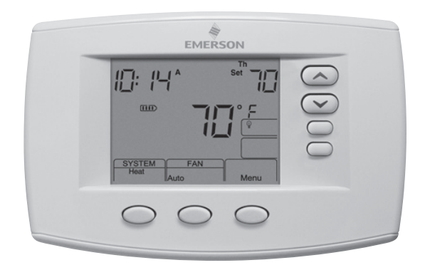
EMERSON White-Rodgers 1F95-0671 Non-Programmable
APPLICATIONS
Save these instructions for future use!
FAILURE TO READ AND FOLLOW ALL INSTRUCTIONS CAREFULLY BEFORE INSTALLING OR OPERATING THIS CONTROL COULD CAUSE PERSONAL INJURY AND/OR PROPERTY DAMAGE.
| Model | Programming Choices | ||
| 1F95-0671 |
7 Day |
5/1/1 Day |
Non-Programmable |
THERMOSTAT APPLICATION GUIDE
| Description | |
| Heat Pump (No Aux. or Emergency Heat) | Yes |
| Heat Pump (with Aux. or Emergency Heat) | Yes |
| Systems with up to 4 Stages Heat, 2 Stages Cool | Yes |
| Heat Only Systems | Yes |
| Millivolt Heat Only Systems – Floor or Wall Furnaces | Yes |
| Cool Only Systems | Yes |
| Gas or Oil Heat | Yes |
| Electric Furnace | Yes |
| Hydronic (Hot Water) Zone Heat – 2 Wires | Yes |
| Hydronic (Hot Water) Zone Heat – 3 Wires | Yes |
| Wired Remote Temperature Sensor (Indoor or Outdoor) | Yes |
| Dual Fuel Feature (Heat Pump Mode, Outdoor Remote Required) | Yes |
SPECIFICATIONS
Electrical Rating:
- Battery Power …………………….. mV to 30 VAC, NEC Class II, 50/60 Hz or DC
- Input-Hardwire . . . . . . . . . . . . . . . . . . . . . . . . . . 20 to 30 VAC
- Terminal Load . . . . . . . . . . . . . . . . . . . . . . . . . . . . . . 1.5A per terminal, 2.5A maximum all terminals combined
- Setpoint Range . . . . . . . . . . . . . . . . . . . . . . . . . . . . . 45 to 99°F (7 to 32°C)
- Differential (Single Stage) . . . . . . . . . . . . . . . . . . . . . Heat 0.6°F; Cool 1.2°F
- Differential (Multi-Stage) . . . . . . . . . . . . . . . . . . . . . . Heat 0.6°F; Cool 1.2°F
- Differential (Heat Pump) . . . . . . . . . . . . . . . . . . . . . . Heat 1.2°F; Cool 1.2°F
- Operating Ambient . . . . . . . . . . . . . . . . . . . . . . . . . . 32°F to +105°F (0 to +41°C)
- Operating Humidity . . . . . . . . . . . . . . . . . . . . . . . . . . 90% non-condensing max.
- Shipping Temperature Range . . . . . . . . . . . . . . . . . . -40 to +150°F (-40 to +65°C)
- Dimensions Thermostat . . . . . . . . . . . . . . . . . . . . . . 4.2″H x 6.4″W x 1.7″D
CAUTION To prevent electrical shock and/or equipment damage, disconnect electric power to system at main fuse or circuit breaker box until installation is complete.
ATTENTION: MERCURY NOTICE
This product does not contain mercury. However, this product may replace a product that contains mercury.
Mercury and products containing mercury must not be discarded in household trash. Do not touch any spilled mercury. Wearing non-absorbent gloves, clean up any spilled mercury and place in a sealed container. For proper disposal of a product containing mercury or a sealed container of spilled mercury, place it in a suitable shipping container. Refer to www.thermostat-recycle.org for location to send product containing mercury.
INSTALLATION
WARNING Thermostat installation and all components of the control system shall conform to Class II circuits per the NEC code.
Remove Old Thermostat
Before removing wires from old thermostat, mark wires for terminal identification so the proper connections will be made to the new thermostat.
Installing New Thermostat
- Pull the thermostat body off the thermostat base. Forcing or prying on the thermostat will cause damage to the unit.
- Place base over hole in wall and mark mounting hole locations on wall using base as a template.
- Move base out of the way. Drill mounting holes. If you are using existing mounting holes and the holes drilled are too large and do not allow you to tighten base snugly, use plastic screw anchors to secure the base.
- Fasten base snugly to wall using mounting holes shown in Figure 1 and two mounting screws. Leveling is for appearance only and will not affect thermostat operation.
- Connect wires to terminal block on base using appropriate wiring schematic.
- Push excess wire into wall and plug hole with a fire resistant material (such as fiberglass insulation) to prevent drafts from affecting thermostat operation.
- Carefully line the thermostat up with the base and snap into place.
Battery Location
2 “AA” alkaline batteries are included in the thermostat at the factory with a battery tag to prevent power drainage. Remove the battery tag to engage the batteries.
To replace batteries, set system to OFF, remove thermostat from wall and install the batteries in the rear along the top of the thermostat (see Figure 1). For best results, use a premium brand “AA” alkaline battery such as Duracell® or Energizer®. If the home is going to be unoccupied for an extended period (over 3 months) and  is displayed, the batteries should be replaced before leaving.
Power Stealing Switch
The Power Stealing Switches (Figure 1, rear view) should be left in the “On” position for most systems. The information in the following table details the thermostat power method and switch options.
| Thermostat Power Method | Switch Position/Description |
| Battery Powered, no 24 Volt system power available. | Switches “On”, thermostat runs on batteries. |
| Hardwired with Battery Back-up, for 24 Volt systems with common connection from transformer to “C” terminal on thermostat. | Switches “On”, thermostat runs on power directly from
transformer with battery back-up. |
| *Battery Powered with Power Stealing Assist, for 24 Volt systems with no common connection from transformer to “C” terminal on thermostat. | Switches “On”, thermostat runs on batteries and supplemental power drawn through the heat or cool circuit. |
Note: Power Stealing Assist is very reliable to increase battery life, but on a small number of heating or cooling systems with high-impedance electronic modules you may observe one of the following conditions:
- The furnace draft inducer motor may run with no call for heat.
- The furnace fan may turn on with no call for heat or may not turn off.
- The furnace may not turn off when the call for heat ends.
- The air conditioner may not turn off when the call for cool ends.
If the Power Stealing Assist method is not compatible with your system, place the Power Stealing Switches to “Off”. This cancels Power Stealing Assist, operates the thermostat on batteries and corrects the condition.
WIRING DIAGRAMS
Refer to equipment manufacturers’ instructions for specific system wiring information. After wiring, see the CONFIGURATION section for proper thermostat configuration. Wiring diagrams shown are for typical systems and describe the thermostat terminal functions.
TERMINAL DESIGNATION DESCRIPTIONS
- O/B…………………………………….. Changeover valve for heat pump energized constantly in cooling and off/heating
- Y2……………………………………… 2nd Stage Compressor
- Y……………………………………… Compressor Relay
- G……………………………………… Fan Relay
- RC……………………………………… Power for Cooling
- RH……………………………………… Power for Heating
- C……………………………………… Common wire from secondary side of cooling (Optional). Required for fault indication, continuous backlight operation or remote temperature sensor operation 6 Powered closed 3rd wire for 3-wire zone valve
- W/E…………………………………….. Heat Relay/Emergency Heat Relay (Stage 1) (3rd Stage Heat in HP2)
- W2……………………………………… 2nd Stage Heat (4th Stage Heat in HP2)
- -……………………………………… Common (DC) for wired remote temperature sensor
- S……………………………………… Frequency signal from remote temperature sensor
- +……………………………………… Power (DC) to remote temperature sensor
- L……………………………………… Compressor diagnostic indicator for systems with diagnostic connection typically found on Heat pump systems or with Copeland’s Comfort Alert

Single Stage and Multi-Stage Connections
Refer to equipment manufacturers’ instructions for specific system wiring information. This thermostat is designed to operate a single-transformer or two-transformer system.
You can configure the thermostat for use with the following systems:
- SINGLE STAGE (SS 1) gas, oil or electric.
- MULTI-STAGE (MS 2) gas, oil or electric.
- After wiring, see INSTALLER CONFIGURATION section for proper thermostat configuration.


Heat Pump Connections
Refer to equipment manufacturers’ instructions for specific system wiring information. This thermostat is designed to operate a single-transformer or two-transformer system. You can configure the thermostat for use with the following systems:
- HEAT PUMP TYPE 1 (HP 1). Single stage compressor system; gas or electric backup.
- HEAT PUMP TYPE 2 (HP 2). Multi-stage compressor or two compressor system with gas or electric backup.
After wiring, see INSTALLER CONFIGURATION section for proper thermostat configuration.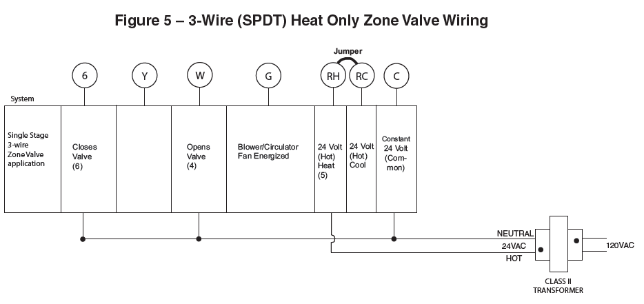
Home Screen Description

Programming and Configuration Items
- “System On” indicates when heating or cooling stage is energized. “System On +2” indicates when additional stages are on.
- The word “Hold” is displayed when the thermostat is in the HOLD mode. “Temp” is displayed when the thermostat is in a Temporary HOLD mode.
- Displays “Change Filter” when the system has run for the programmed filter time period as a reminder to change or clean your filter.
- Displays “Set” for setpoint when in Run Program mode.
- Displays System Mode (Heat, Em, Auto, Cool, Off) or Time in menu mode.
- Displays Fan mode (On, Auto) “Prog FAN On” or “Run Sched” in Menu mode.
- Displays “Run Schedule”, “Schedule”, or “Menu”.
- Displays “Save” when Cool SavingsTM is working.
- Displays “Heat Pump” when system is configured as Heat Pump thermostat.
- Displays “Hold” in programmable mode when not in Hold mode. Displays Light Bulb in non-programmable mode.
- Initially displays “Auto Sched”. If Auto Schedule had been used or disabled, then it displays “Cool Savings” when in the Cool Mode. Displays “Copy” in Schedule mode and “Fan” in Fan Schedule mode.
- “Call For Service” indicates a diagnostic fault in the heating/cooling system, it does not indicate a fault in the thermostat.
- “Keypad Lockout” in Menu mode when selecting keypad Lockout or in RUN when a keypad Lockout is active.
Thermostat must be in Heat, Cool or Auto. Press and hold the Menu button for at least 5 seconds. The display will show item #1 in the table below. Press  Menu to advance to the next menu item. Press or to change a menu item options.
| INSTALLER/CONFIGURATION MENU | ||||||
| Menu Ref. | HP | SS | Press Button | Displayed (Factory Default) | Press to select from listed options |
Comments |
| 1 | 1 | 1 | MENU | (MS 2) | HP 1, HP 2, SS 1 | Selects Multi-Stage (MS 2 No Heat Pump), Heat Pump 1 (HP 1, 1 compressor),
Heat Pump 2 (HP 2, 2 compressor or 2 speed compressor), or Single Stage (SS 1) |
| 2 | 2 | 2 | MENU | (GAS) for SS or MS (ELE) for HP | ELE | GAS setting: furnace controls the blower ELE setting: thermostat controls the blower |
| 3 | 3 | 3 | MENU | CS (3) | 0, 1, 2, 4, 5, 6 | Selects Cool Savings Value 1 (low) to 6 (high), Value 0 disables feature |
| 4 | 4 | 4 | MENU | E (On) | OFF | Selects Energy Management Recovery (EMR) On or OFF. |
| 5 | – | 5 | MENU | CR Heat (ME) | SL, FA | Selects Adjustable Anticipation, cycle rate, Heat (This item only appears when MS 2 or SS 1 is selected above) |
| 6 | 5 | – | MENU | CR Heat Pump (ME) | SL, FA | Selects Adjustable Compressor Anticipation (Heat Pump) This item only appears when HP 1, HP 2 is selected above |
| 7 | 6 | 6 | MENU | CR Cool (ME) or
CR AU (FA) |
SL, FA SL | Selects Adjustable Anticipation, cycle rate, cool (when MS 2 or SS 1 is selected above.) or Selects the cycle rate for Auxiliary stage (when HP 1 or HP 2 is selected above) |
| 8 | 7 | 7 | MENU | CL (OFF) | CL On | Compressor Lockout Time |
| 9 | 8 | 8 | MENU | Em Heat, Auto Cool Off
or Heat, Auto,Cool Off |
Heat Cool Off, Heat Off with Fan icon, Heat Off without Fan icon
Cool Off, Auto Off |
System Mode Configuration
with Automatic Changeover capability |
| 10 | 9 | 9 | MENU | dL (On) | dL OFF | Selects Display Light On or OFF |
| 11 | 10 | 10 | MENU | 0
(current temperature) |
1 HI, 2 HI, 3HI, 4 HI,
1 LO, 2 LO, 3 LO, 4 LO |
Adjustable Ambient Temperature Display |
| 12 | 11 | 11 | MENU | °F | °C | Selects Fahrenheit/Celsius Temperature Display |
| 13 | 12 | 12 | MENU | (On) b | OFF | Select Beeper OFF to stop audible
key feedback (not applicable on all models) |
| 14 | 13 | 13 | MENU | P (7) | 3, 0 | Defaults 7-day programming (P7) but non- programmable (0) or 5/1/1 programming (P3) is available on most models. |
| 15 | 14 | 14 | MENU | PS (4) | 2 | Selects Program periods per day: 4 = Morn, Day, Eve, Night
2 = Day, Night |
| 16 | 15 | 15 | MENU | Heat AS (On) | OFF | Automatic Schedule for heat mode |
| 17 | 16 | 16 | MENU | Cool AS (On) | OFF | Automatic Schedule for cool mode |
| 18 | 17 | – | MENU | Heat FA (On) | OFF | Fast Heat option may be disabled by selecting OFF. NA to SS or HP1 config. |
| 19 | 18 | – | MENU | Cool FA (On) | OFF | Fast Cool option may be disabled by selecting OFF. NA to SS or HP1 config. |
| 20 | 19 | 17 | MENU | Remote (OFF) | On | Selects Remote Sensor On/OFF |
| MENU | Remote (In) | Outdoor | Selects Remote Sensor to outdoor NA is Remote Sensor OFF | |||
| MENU | Indoor Loc (On) | OFF | Selects Local Sensor (in thermostat) to OFF. N/A if Remote is selected to Outdoor | |||
| 21 | 20 | 18 | MENU | dS (On) | Off | Selects Automatic Daylight Saving Time option |
| 22 | 21 | 19 | MENU | (OFF)
Keypad Lockout |
L, P, Limit | Selects one of 3 Keypad Lockout configurations L – Total Keypad Lockout
P – Partial Keypad Lockout (Up and Keys still work) Limit – Limited Temperature Range |
| MENU | (000)
Keypad Lockout |
1-999 | Selects personal lockout code. 000 is NOT A VALID CODE. | |||
| 23 | 22 | 20 | MENU | L Heat (99) | L 62 to L 98 | Select Limited HEAT Range Temperature |
| 24 | 23 | 21 | MENU | L Cool (45) | L 46 to L 82 | Select Limited COOL Range Temperature |
| 25 | 24 | – | MENU | CO (05) | 06-50 | Selects outdoor Compressor OFF temperature (Balance Point temperature). 05 disables feature. Outdoor Remote required |
| MENU | (dF) | EA | Selects between dF (dual Fuel) or EA (Electric Aux) only available if CO is greater than 05 | |||
| MENU | Cd (60) | Selects Compressor delay OFF time in seconds (only if dF is selected) | ||||
| 26 | 25 | – | MENU | AO (80) | Selects AO (Auxiliary OFF) temperature. Fea- ture disabled if 80 is selected. Outdoor Remote required | |
| 27 | 26 | 22 | MENU | Change Filter (OFF) | On | Selects Filter Change-out Indicator On or OFF. |
| MENU | Change Filter (200 h) | 25-1975 h | Change Filter time in 25 hour increments. This menu only appears if On is selected in above. | |||
| 28 | 27 | 23 | MENU | (OFF)
Change UV Lamp |
On | Selects UV Lamp Timer: On/OFF |
| MENU | (350)
Change UV Lamp |
25-1975 | Selects number of Days between changing UV Lamp | |||
| 29 | 28 | 24 | MENU | Cool On (o) | Heat On (b) | Selects operation of the reversing valve terminal (O/B) output as an O or B terminal |
| 30 | 29 | 27 | MENU | RUN SCHED | Returns to Normal Operation |
- 1) This control can be configured for:
MS 2 – Multi-Stage System (no heat pump)
HP 1 – Heat Pump with one stage of compressor
HP 2 – Heat Pump with two stage compressor or two compressor system, Gas or Electric backup
SS 1 – Single Stage System - 2) GAS or Electric (ELE) fan operation. If the heating system requires the thermostat to energize the fan, select ELE. Select GAS if the heating system energizes the fan on a call for heat.
- 3) Select Cool Savings™ value – Select the amount of adjustment for the Cool Savings™ feature in Cool mode with 1 (1°) being the least amount of adjustment and 6 (6°) being the most amount of adjustment. Default value is 3. Cool Saving is an optional energy-saving feature that can reduce your cooling costs. It is based on the principal that lower indoor humidity makes a slightly higher temperature feel more comfortable. Cool Savings operates during periods of high demand which normally occur on the hottest summer days when a cooling system may run for hours to reach the thermostat setting. Long cooling run times also lower indoor humidity. Cool Savings, very slowly, adjusts the setpoint temperature to make the setpoint closer to the displayed room temperature, to a maximum of the number of degrees you select. Adjusting the setpoint temperature over a long cooling run time allows the system to reach your set temperature and turn off. The room temperature will actually be higher than the thermostat displays but the reduction in humidity will allow comfort at the slightly higher temperature.
To turn this feature on in the Cool mode press Cool Savings. The display will show “Save” next to the set-point temperature. When Cool Savings is making adjustments to the room temperature display “Save” will be flashing and the displayed room temperature may vary within the adjustment range you selected.
If “Save” is not displayed and this feature is OFF, no change will occur when the cooling system is continuously running during periods of high demand. - 4) Energy Management Recovery: (this step is skipped if configured to be non-programmable).
Energy Management Recovery (E) On enables the thermostat to start heating or cooling early to make the building temperature reach the program setpoint at the time you specify. Heating will start approximately 5 minutes early (15 minutes for heat pump) for every 1° of temperature required to reach setpoint.
Example: E On is selected and your heating is programmed to 65° at night and 70° at 7 AM. If the building temperature is 65°, the difference between 65° and 70° is 5°. Allowing 5 minutes per degree, the thermostat setpoint will change to 70° at 6:35 AM. Cooling allows approximately 15 minutes per degree, because it takes longer to reach set temperature. - 5, 6 & 7) Cycle Rate Selection – The factory default setting for Heat and Cool modes, SS1, MS2, is medium cycle (ME). For Heat Pump, HP1, HP2, the default setting is medium (ME). For Emer (Aux) the default setting is fast cycle (FA). To change cycle rate, press or button. Cycle rate differentials for different settings are:
MODE Fast (FA) Medium (ME) Slow (SL)- Heat (SS1, MS2) 0.4°F 0.6°F 1.7°F
- Cool (SS1, MS2) 0.9°F 1.2°F 1.7°F
- Heat Pump(HP1,HP2) 0.9°F 1.2°F 1.7°F
- Emer (HP1, HP2) 0.6°F – 1.7°F
- 8) Select Compressor Lockout CL OFF or ON – Selecting CL ON will cause the thermostat to wait 5 minutes be-tween cooling cycles. This is intended to help protect the compressor from short cycling. Some newer compressors already have a time delay built in and do not require this feature. Your compressor manufacturer can tell you if the lockout feature is already present in their system. When the thermostat compressor time delay occurs, it will flash the setpoint for up to five minutes.
- 9) System Mode Configuration – This thermostat is config- ured for Heat and Cool (SYSTEM switch with Cool Off Heat) default. It can also be configured for Heat and Cool with Auto changeover (Heat, Auto, Cool, Off), Heat only with fan (Off Heat), Heat only without fan, Auto only
(Auto Off), and Cool only (Cool Off). - 10) Select Backlight Display – The display backlight improves display contrast in low lighting conditions. When the “C” terminal is powered, selecting backlight CdL ON will keep the light on continuously. Select backlight OFF will turn the light on momentarily after any button is pressed. When the “C” terminal is not powered, the light will be on momentarily after any button is pressed no matter whether the backlight is selected ON or OFF.
- 11) Select Temperature Display Adjustment 4 LO to 4 HI –Allows you to adjust the room temperature display up to 4°higher or lower. Your thermostat was accurately calibrated at the factory, but you have the option to change the dis- play temperature to match your previous thermostat. The current or adjusted room temperature will be displayed.
- 12) Select F° or C° Readout – Changes the display readout to Celsius or Fahrenheit as required.
- 13) Select Audio Prompting (Beeper) On or Off – Factory default setting is on (b, On). To turn off the beeper, select OFF. Some models do not have a beeper. This setting has no effect on models without beeper.
- 14) Program Options: Selects configuration for 7 day (7) or 5/1/1 day (3) programming or non-programming (0) mode. The default setting is 7, indicating 7 day programming. The programs per week can be changed to 3 or 0 by pressing the buttons. A selection of 0 days for non-programmable will eliminate the need for EMR, and that step in the menu will be skipped.
- 15) Program Steps per day – This control can be configured for 4 or 2 program steps per day. Default is “4 PS” and can be toggled between 4 PS and 2 PS.
- 16 & 17) Select Automatic Schedule – With just one touch of the Auto Schedule key this feature allows you to program a desired comfort temperature into all the program periods along with a 6° set back for night periods of both Heat and Cool programs. Factory default is “On” for both. When Heat AS On and Cool AS On are activated while in Heat or Cool mode, select desired setpoint temperature and press Auto Schedule. This value will be copied into all the morning, day and evening program periods. The night program periods will have a 6°F set back.
- 18 & 19) Select Fast Second Stage ON or OFF – Heat pump or Multi-stage only, in the run mode, with the fast Heat feature enabled (FA Heat On), if the Heat setpoint temperature is manually raised by 3°F (2°C) or more above the actual temperature using
 the second stage will energize immediately. With FA OFF, second stage will not energize until the setpoint temperature is 1°F or more above actual temperature for more than ten minutes. The Fast Cool feature (FA Cool) provides the same controls when the setpoint temperature is lowered.
 - 20) Select Remote Temperature Sensor – This control allows one wired remote temperature sensor (indoor, F145-1328, or outdoor, F145-1378) be connected to it and indicates the measured temperature in clock digits. This menu enables you to select the remote sensor and also configure it as indoor or outdoor temperature sensor. Factory default is off. Select Remote On and Remote in (for indoor) or Outdoor Remote.
Local Temperature Sensor disable – This is applicable only when indoor remote temperature sensor is enabled. Factory default is Loc On. You can make it Loc Off if you desire by usingbuttons. Then, only the indoor remote temperature reading will be used for control - 21) Select Daylight Saving Time Calculation – This feature will allow the thermostat to calculate the DST automatically and apply it to the Real Time Clock display. Default On. Use touch keys to select the feature OFF.
- 22) Keypad Lockout – This step allows you to select the type of lockout or limited-range security required. If no lockout or limited-range security is required, press MENU to advance the menu.
Three security settings are available in this menu item. Use the buttons to select the lockout desired.
Lockout selections are:- “Keypad Lockout and L” = Total Lockout. Total Lockout locks all keys.
- “Keypad Lockout and P” = Partial Lockout. Partial Lockout allows only the buttons to operate within your set temperature limits.
- “Keypad Lockout and Limit” prevents changing the temperature limits in the Configuration Menu. Press Menu after selecting the type of lockout.
- “Keypad Lockout Combination Number Selection”
Display will read “000” “Keypad Lockout”. Note: “000” is not a valid combination choice. Skip this step and continue through the remaining configuration menu items if you require an Air Filter Change out indicator or Humidifier Pad Change out indicator by pressing the MENU button to advance. - Return to this point when you are ready to start your selected lock-out and continue by:
Press. Display will read “001”.
Pressingbuttons to select your keypad lockout combination number. - Record the number you select for future use.
Press MENU or RunSched to exit the menu. The security feature you select will start. The system button will remain active for 10 seconds to allow setting Heat, Off, Cool or Auto.
- 23) Limited Heat Range – This feature provides a maximum setpoint temperature for heat. The default setting is 99°F. It can be changed between 62°F and 98°F by pressing the button.
- 24) Limited Cool Range – This feature provide a minimum setpoint temperature for cool. The default setting is 45°F. It can be changed between 46°F and 82°F by pressing the or button.
- 25) Select Compressor Off (CO) Feature Using Outdoor Sensor – This feature is applicable only in heat pump modes and with an outdoor sensor installed and enabled. When CO is enabled by selecting a temperature >05°F (-15°C), the thermostat will use the outdoor sensor temperature to determine when to switch to gas heat and shut down the compressor.
When the outdoor temperature goes below the selected temperature, the gas heat will begin. Default is 05 (Off or disabled), but can be set in the range of 06 to 50 using thebuttons.
Select dF or EA – If CO is set > 05°F (-15°C), select dF (default) if your system has a fossil fuel (gas or oil) Auxiliary heat. Select EA if your system has Electric Auxiliary heat and you want the compressor to continue to run while calling for Auxiliary stage.
Select Compressor Delay (Cd) – If dF is selected, after the auxiliary heat is turned on, the compressor(s) shut down is delayed for the time selected (in seconds). This delay is factory set to 60, but can be set in the range of 0 to 99 using or buttons. - 26) Select Auxiliary Off (AO) – This feature is applicable only in heat pump modes and with an outdoor sensor installed and enabled. Select the temperature that will inhibit the auxiliary heating stage. As long as the outdoor temperature is above the setpoint, the auxiliary heat will not turn on. The default setting is 80, but can be set in the range of 35 to 79. A setting of 80 disables this feature.
- 27) Select Filter Replacement Reminder and Set Run Time Select the “Change Filter” reminder On or OFF. If selected On, press MENU to select the time period from 25 to 1975 hours in 25 hours increments. In a typical system, 200 hours (default) of run time is approximately 30 days. After the selected time of blower operation, the thermostat will display “Change Filter” as a reminder to change or clean your air filter. When “Change Filter” is displayed, press MENU or RUN SCHED button to clear the display and restart the time to the next filter change.
- 28) Change UV Lamp – This feature allows the thermostat to display the words “Change UV Lamp” (Call for Service of UV bulb) after a set time of UV bulb operation. This is a reminder to maintain your UV system at optimum level of operation. When enabled the factory set interval for “Change UV Lamp” to be displayed is 350 days of UV bulb operation and can be adjusted in 25 day increments.
This should be adjusted with respect to the bulb’s recommended maintenance schedule. When “Change UV Lamp” is displayed, you can clear it by pressing MENU. - 29) Select Reversing Valve Output – The O/B option is factory set at “O” position. This will accommodate the majority of heat pump applications, which require the changeover relay to be energized in COOL. If the thermostat you are replacing or the heat pump being installed with this thermostat requires a “B” terminal, to energize the changeover relay in HEAT, the O/B option should be set at “B” position.
OPERATING YOUR THERMOSTAT
Check Thermostat Operation
NOTE To prevent static discharge problems, touch side of thermostat to release static build-up before touching any keys.
If at any time during testing your system does not operate properly, contact a qualified service person.
Fan Operation
If your system does not have a G terminal connection, skip to Heating System.
- Turn on power to system.
- Press FAN button to select ON. The blower should begin to operate.
- Press FAN button to select AUTO. The blower should stop immediately.
CAUTION Do not allow the compressor to run unless the com-pressor oil heaters have been operational for 6 hours and the system has not been operational for at least 5 minutes.
Heating System
- Press SYSTEM button to select Heat. If the auxiliary heating system has a standing pilot, be sure to light it.
- Pressto adjust thermostat setting to 1° above room temperature. The heat pump system should begin to oper-ate. The display should show “System On”. However, if the system configuration is set to HP1 or HP2 and setpoint temperature display is flashing, the 5 minute compressor lockout feature is operating (see Configuration menu, item 11).
- Adjust temperature setting to 3° above room temperature. If your system configuration is set at MS2, HP2 or HP1, the auxiliary heat system should begin to operate and the display will show “System On +2”.
- Press
 to adjust the thermostat below room temperature. The heating system should stop operating.
Emergency System
EM bypasses the Heat Pump to use the heat source wired to terminal W/E on the thermostat. EM is typically used when compressor operation is not desired, or you prefer backup heat only.
- Press SYSTEM button to select EM. “EM” will flash on the display.
- Press to adjust the thermostat setting above room temperature. The Emergency heating system will begin to operate. The display will show “System On” and flash “EM” to indicate that the Emergency system is operating.
- Press to adjust the thermostat below room temperature. The Emergency heating system should stop operating.
CAUTION To prevent compressor and/or property damage, if the outdoor temperature is below 50°F, DO NOT operate the cooling system.
Cooling System
- Press SYSTEM button to select Cool.
- Pressto adjust thermostat setting below room temperature. The blower should come on immediately on high speed, followed by cold air circulation. The display should show “System On”. If the setpoint temperature display is flashing, the compressor lockout feature is operating (see Configuration menu, item 5).
- Adjust temperature setting to 3° below room temperature. The second stage cooling should begin to operate and the display should show “System On +2”.
- Press to adjust the temperature setting above room temperature. The cooling system should stop operating.
Choose the Fan Setting (Auto or On)
Fan Auto is the most commonly selected setting and runs the fan only when the heating or cooling system is on.
Fan On selection runs the fan continuously for increased air circulation or to allow additional air cleaning.
Fan Prog On indicates that the fan is programmed to be on for the entire period. The Prog Fan On can be overridden
to have the fan cycle with the system. Press the FAN button to change the fan to Auto. The fan programming will be overridden until the next program period begins or until Run Schedule is pressed.
PROGRAMMING
Set Current Time and Day
- Press Menu button to enter installer menu. Then press Time button once to indicate hour & AM or PM designation in clock display.
- Press and hold either the button until you reach the correct hour and AM or PM designation.
- Press Time again to display minutes only in clock display.
- Press and hold either the button until you reach the correct minutes.
- Press Time once again to display year.
- Press and hold either thebutton until you reach the correct year.
- Press Time once again to display month.
- Press and hold either thebutton until you reach the correct month.
- Press Time once again to display date of the month along with day of the week at top row (which is automatic).
- Press and hold either thebutton until you reach the correct day of the month and day of the week is automatically calculated and displayed at the top row.
- Press RunSched button once; now the display will show the correct time and room temperature.
PROGRAMMING
Energy Saving Factory Pre-Program
The 1F95-0671 thermostats are programmed with the energy saving settings shown in the table below for all days of the week. If this program suits your needs, simply set the thermostat clock and press the RunSched button. The table below shows the factory set heating and cooling schedule for all days of the week.
| * Wake Up (Morn) | Leave For Work (Day) | * Return Home (Eve) | Go To Bed (Night) | |||||
| Heating Program | 6:00 AM | 70°F | 8:00 AM | 62°F | 5:00 PM | 70°F | 10:00 PM | 62°F |
| Cooling Program | 6:00 AM | 75°F | 8:00 AM | 83°F | 5:00 PM | 75°F | 10:00 PM | 78°F |
Note: You can eliminate these two program periods in the configuration menu (reference #15) if the building is occupied all day. Day period will change to 6:00 AM and 70° and can be programmed as required.
Planning Your Program – Important
The Heating and Cooling Program schedules below allow you to pencil in your own program times and temperatures.
The 1F95-0671 comes configured for 7 day programming and can also be configured for 5+1+1 programming (see configura-tion section).
Factory settings are listed on Monday, Saturday and Sunday. If you are re-programming a 5+1+1 day schedule, pencil in your own times and temperatures directly below the factory times and temperatures.
If you are re-programming a 7 day schedule, fill in all lines with the times and temperatures you want. Keep the following guidelines in mind when planning your program.
- In Heating, lower temperatures will save energy.
- In Cooling, higher temperatures will save energy.
- If you plan on using Auto Changeover, do not program the heating temperature higher than the cooling temperature.
Worksheet for Re-Programming 5+1+1 and 7 Day Program
| Heating Program | Wake Up (Morn) |
Fan |
Leave For Work (Day) |
Fan |
Return Home (Eve) |
Fan |
Go To Bed (Night) |
Fan |
||||
|
MON |
6:00 AM | 70°F | Auto | 8:00 AM | 62°F | Auto | 5:00 PM | 70°F | Auto | 10:00 PM | 62°F | Auto |
| TUE | ||||||||||||
| WED | ||||||||||||
| THU | ||||||||||||
| FRI | ||||||||||||
|
SAT |
6:00 AM | 70°F | Auto | 8:00 AM | 62°F | Auto | 5:00 PM | 70°F | Auto | 10:00 PM | 62°F | Auto |
|
SUN |
6:00 AM | 70°F | Auto | 8:00 AM | 62°F | Auto | 5:00 PM | 70°F | Auto | 10:00 PM | 62°F | Auto |
| Cooling Program | Wake Up (Morn) |
Fan |
Leave For Work (Day) |
Fan |
Return Home (Eve) |
Fan |
Go To Bed (Night) |
Fan |
||||
|
MON |
6:00 AM | 75°F | Auto | 8:00 AM | 83°F | Auto | 5:00 PM | 75°F | Auto | 10:00 PM | 78°F | Auto |
| TUE | ||||||||||||
| WED | ||||||||||||
| THU | ||||||||||||
| FRI | ||||||||||||
|
SAT |
6:00 AM | 75°F | Auto | 8:00 AM | 83°F | Auto | 5:00 PM | 75°F | Auto | 10:00 PM | 78°F | Auto |
|
SUN |
6:00 AM | 75°F | Auto | 8:00 AM | 83°F | Auto | 5:00 PM | 75°F | Auto | 10:00 PM | 78°F | Auto |
Automatic Daylight Saving Calculation
The Real Time Clock will adjust automatically for daylight savings time, in the following manner:
Increment one hour at 2 AM on the second Sunday of March and decrement one hour at 2 AM on the first Sunday of November. (New DST effective 2007).
The daylight saving feature can be enabled or disabled in installer configuration menu. Default is DS ON (enabled). After entering installer configuration mode, momentarily press MENU button until the display indicates dS (in actual temperature digits) and on (default – in clock digits). buttons will toggle display and operation from on to OFF.
Programming Tip: Copy Program
When programming your thermostat, you may copy the program from one day to another day or group of days using the Copy key. In 7 day programming mode, a day can be copied to another day or all six other days. In 5/1/1 day programming mode the weekday (Mon – Fri) program can be copied into Sat and Sun or either Sat or Sun.
To copy a program from one day to another:
- In Set Schedule mode, enter the program for the day or select the day you wish to copy by pressing Advance Day.
- Press Copy. On the display, “Copy” will begin to flash. The day of the week being copied will show.
- Press Advance Day. The day being copied will be indicated and the other days will be flashing.
- If you wish to copy to all days skip to next step or press Advance Day until the day you wish to copy to is flashing.
- Press Copy. “Copy” will be on, the day you copied from will disappear and the day(s) you copied to will be on.
- If you wish to copy this same program into other days, press Copy and repeat steps 2 through 5.
- Press RunSched to return to normal operation.
Fill in the blank schedule on the next page then:
Enter the Heating Program
- Press SYSTEM button to select Heat in the system switch area indicating the active mode being programmed.
- Press the Menu button and then press Schedule.
- The top of the display will show the day(s) being programmed. The first period to be programmed will appear. The set temperature will also be displayed and the time will be flashing to indicate that the time can be changed.
- Press buttons to adjust the start time for the period. The time will change in 15 minute increments.
- Press the System Time button to change to the temperature flashing.
- Pressbuttons to change the temperature to your selected temperature for the first heating period.
- After you have set the time and temperature for the first period, press Schedule to advance to the next program period.
- Repeat steps 4 through 7 until all of the program times and temperatures are entered for all program periods for that day.
- Press Schedule button to change to the next day and repeat steps 4 through 8 until all program days and periods are entered.
- When programming is complete and all of the times and temperatures match your desired heating schedule, press RunSched. The thermostat will now run your program.
Enter the Cooling Program
- Press the SYSTEM button until the Cool icon appears.
- Follow Enter Heating Program instructions for entering cooling times and temperatures.
Automatic Schedule
This feature provides a method to program every day with the most popular time and temperature settings using one key. For this feature to be available, the Auto Schedule options (Installer/Configuration menu item 16, AS Heat, or item 17, AS Cool) must be selected On.
To use Auto Schedule, press RunSched to be sure you are in normal operating mode. In SYSTEM Heat mode, use the keys to select your “Comfort Temperature”. When your “Comfort
Temperature” is selected, press Auto Sched button. The Auto Schedule key will disappear to indicate that the Auto Schedule command has been accepted.
In Heat mode the thermostat will maintain your “Comfort Temperature” during the Morning, Day and Evening periods and setback 6° for the Night. Morning period will begin at 6:30 AM and Night period will begin at 10:30 PM.
To set the Auto Schedule temperature for Cool mode, press SYSTEM to change the mode to Cool and repeat setting the temperature. In Cool mode, the thermostat will maintain your selected “Comfort Temperature” continuously.
The “Comfort Temperature” can be temporarily overridden by changing the setpoint temperature using the buttons. Once Auto Schedule has been set and the key has disappeared, it can be reset in the Installer/ Configuration menu.
Entering Fan Program
The fan can be programmed to turn on at the beginning of a period and remain on through the whole period. In RunSched mode when the FAN switch indicates Prog Fan On the fan is programmed to be on for the period.
- Press System button to select either Heat or Cool.
- Press Menu button and then press Fan button to the right of the display.
- The top of the display will show the day(s) being programmed. The first period to be programmed will appear.
- Press the Fan button to change from Auto to Prog.
- Press the Fan button to the right of the display to change to the next period.
- Repeat steps 4 and 5 to program the fan for all periods of the day.
- Press Fan to advance to the next day of the week and repeat steps 4 through 7 to program the fan for all days of the week.
Wired Remote Temperature Sensing
One remote temperature sensor can be installed indoor or outdoor and connected to the thermostat by a maximum cable length of 100 meters (300 feet). Terminals +, S and – on the terminal block allow connection of the remote sensor. The thermostat must have 24 VAC Common connection to terminal C for the remote sensor to operate. The remote sen-sor can be enabled or disabled in the Installer/Configuration menu, item 20.
When remote sensor, Remote, is selected Off (factory de-fault), no remote sensor is enabled. When remote sensor is selected On, the next step is to select the remote as indoor, Remote In, or outdoor, Remote Outdoor. If the remote is se-lected as Remote In, an additional step will be to select if the temperature shown on the display will be from the thermostat, Loc On, or the remote sensor Loc Off.
In normal operation, when a remote sensor is enabled the time digits of the display will alternate between the time and the remote temperature for three seconds each. Above the remote temperature will be “Remote”, for indoor sensor or “Outdoor Remote”, for outdoor sensor. If the remote sensor is an indoor sensor and the local display has been disabled, the temperature displayed as the room temperature will be the remote sensor temperature.
Sensing Range:
- Outdoor temperature range is -40oF to 140oF
- Indoor temperature range is 32oF to 99 oF
Weighing of Remote Reading:
The thermostat will weight or average the temperature of the indoor remote sensor with the local sensor in the thermostat for each program period. The averaging will be active only when the local sensor and the indoor remote sensor are both functional and enabled in the Installer/Configuration menu.
When the thermostat is in the Set Schedule mode, the weight of the indoor sensor will be shown in the current temperature digits of the display. The weight will show as A2 (average and default), H4 (high) or L1 (low). Pressing the but-tons at the same time will change the weight for the program period. The weight of the thermostat sensor is fixed. In normal operation of the thermostat, the current tempera-ture displayed will be the weighted average of the local sensor and the remote sensor using the formula (local sensor weight x local sensor temperature) + (remote sensor weight x remote sensor temperature) / (local sensor weight + remote sensor weight).
Example: Local sensor temperature is 80° and the remote sensor is 70°.
- If weight is selected H4, the averaged temperature of 72° will be displayed. (1 x 80) + (4 x 70) / 5 = 72°
- If weight is selected A2, the average temperature of 73° will be displayed. (1 x 80) + (2 x 70) / 3 = 73.3°
- If weight is selected L1, the average temperature of 75° will be displayed. (1 x 80) + (1 x 70) / 2 = 75°
The example shows that the weight selected would prioritize the overall averaged temperature between the two sensors. The high weight selection caused the remote sensor to have a higher influence in the calculated temperature average than the local sensor and the low weight selection caused the remote sensor to have less influence.
Dual Fuel Temperature Setpoint
When the thermostat is configured for Heat Pump mode and an outside remote sensor is installed and enabled, the thermostat can monitor the outside temperature to determine when to switch to auxiliary heat and shut down the compressor. This eliminates the need for a fossil fuel kit.
The Compressor Off temperature (CO) set in the configuration menu, item 25, will determine when the auxiliary heat will start and the compressor will shut off. The default setting is 05°F. -15°C (feature disabled) and can be set for 06 to 50°. When the outside temperature falls to the selected temperature, the auxiliary heat system will begin.
The auxiliary heat system can be fossil fuel (dF) or electric heat (EA). This is selected after CO is set greater than 05°. If the auxiliary heat is fossil fuel, (df), a delay time for the compressor shut down (Cd) can be selected. The default for this delay is 60 seconds but can be set from 0 to 99 seconds. If EA is selected, there is no selection for Cd because the compressor will shut down immediately.
TROUBLESHOOTING
Reset Operation
Note: When thermostat is reset, installer configuration menu settings and programming will reset to factory settings.
If a voltage spike or static discharge blanks out the display or causes erratic thermostat operation, you can reset the thermostat by removing the wires from terminals R and C (do not short them together) and removing batteries for 2 minutes. After resetting the thermostat, replace the wires and batteries. If the thermostat has been reset and still does not function correctly contact your heating/cooling service person or place of purchase.
Note: Be sure to review the installer configuration menu settings.
To reset the programming, clock and configuration settings, press the and SYSTEM button simultaneously. The thermostat should go blank and then all segments will be displayed momentarily.
| Symptom | Possible Cause | Corrective Action |
| No Heat/No Cool/No Fan (common problems) | 1. Blown fuse or tripped circuit breaker.
2. Furnace power switch to OFF. 3. Furnace blower compartment door or panel loose or not properly installed. 4. Loose connection to thermostat or system. |
Replace fuse or reset breaker. Turn switch to ON.
Replace door panel in proper position to engage safety interlock or door switch. Tighten connections. |
| No Heat | 1. Pilot light not lit.
2. Furnace Lock-Out Condition. Heat may also be intermittent.
3. Heating system requires service or thermostat requires replacement. |
Re-light pilot.
Many furnaces have safety devices that shut down when a lock-out condition occurs. If the heat works intermittently contact the furnace manufacturer or local HVAC service person for assistance. Diagnostic: Set SYSTEM Switch to HEAT and raise the setpoint above room temperature. Within a few seconds the thermostat should make a soft click sound. This sound usually indicates the thermostat is operating properly. If the thermostat does not click, try the reset operation listed above. If the thermostat does not click after being reset contact your heating and cooling service person or place of purchase for a replacement. If the thermostat clicks, contact the furnace manufacturer or a HVAC service person to verify the heating is operating correctly. |
| No Cool | 1. Cooling system requires service or thermostat requires replacement. | Same as diagnostic for No Heat condition except set the thermostat to COOL and lower the setpoint below the room temperature. There may be up to a five minute delay before the thermostat clicks in Cooling. |
| Heat, Cool or Fan Runs Constantly | 1. Possible short in wiring.
2. Possible short in thermostat. 3. Possible short in heat/cool/fan system. 4. FAN Switch set to Fan ON. |
Check each wire connection to verify they are not shorted or touching together. No bare wire should stick out from under terminal block. Try resetting the thermostat as de- scribed above. If the condition persists the manufacturer of your system or service person can instruct you on how to test the Heat/Cool system for correct operation. If the system operates correctly, replace the thermostat. |
| Thermostat Setting & Thermostat Thermometer Disagree | 1. Thermostat thermometer setting requires adjustment. | The thermometer can be adjusted +/- 4 degrees. See Temperature Display Adjustment in the Configuration Menu section. |
| Furnace (Air Conditioner) Cycles Too Fast or Too Slow (narrow or wide temperature swing) | 1. The location of the thermostat and/or the size of the Heating System may be influencing the cycle rate. | Digital thermostats provide precise control and cycle faster than older mechanical models. The system turns on and off more frequently but runs for a shorter time so there is no increase in energy use. If you would like an increased cycle time, choose SL for slow cycle in the Configuration menu, step 7 (heat) or 8 (cool). If an ac-
ceptable cycle rate is not achieved, contact a local HVAC service person for additional suggestions. |
| Forgot Keypad Lockout Code | Press the menu button (button will disappear) and hold in for 20 seconds. This unlocks the thermostat. |
White-Rodgers is a business of Emerson Electric Co.
The Emerson logo is a trademark and service mark of Emerson Electric Co.
HELP LINE: 1-800-284-2925
www.white-rodgers.com
www.emersonclimate.com
Other manuals
EMERSON White-Rodgers 1F95-0671 Non-Programmable specification sheet
Download Manuals
EMERSON White-Rodgers 1F95-0671 Non-Programmable Installation and Operating Instructions

EMERSON White-Rodgers 1F95-0671 Non-Programmable Installation and Operating Instructions