
Autani 1000172-01 Touchscreen Programmable Thermostat
APPLICATION
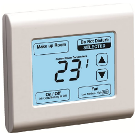
The Wave touchscreen programmable thermostat delivers universal system compatibility, precise comfort control and easy 7-day programming. The Wave provides temperature control for gas, oil, electric, and heat pumps for up to 3 heat/2 cool systems.
FEATURES
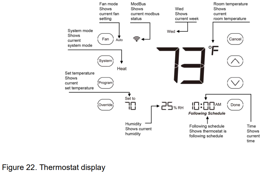
- Large, clear display with backlight allows for easy reading, even in the dark
- Temperature and set temperature are displayed
- Intuitive touchscreen interface makes setup effortless
- Sophisticated appearance with an ergonomic design
- Capacitance touchscreen interaction
- Compressor protection
SPECIFICATIONS
Temperature Setting Range
- Heating: 41°F to 120°F (5°C to 49°C)
- Cooling: 43°F to 122°F (6°C to 50°C)
Operating Ambient Temperature
- 32°F to 122°F (0°C to 50°C)
Shipping Temperature
- 14°F to 140°F (-10°C to 60°C)
Operating Relative Humidity (Non-condensing)
- IRS–1: 5% to 95%
- ORS-1: 5% to 95%
Humidity Display Range
- 0% to 99%
Clock Accuracy
- +/- 2 minute per month
Cool Indication
- Wave shows “Cool On” on the screen when Cool is activated
Heat Indication
- Wave shows “Heat On” on the screen when Heat is activated
Auxiliary Heat Indication
- Wave shows “Aux On” on the screen when Auxiliary Heat is activated
INSTALLATION
When Installing this Product…
- Read these instructions carefully. Failure to follow the instructions can damage the product or cause a hazardous condition.
- Check the ratings given in the instructions to make sure the product is suitable for your application.
- Installer must be a trained, experienced service technician.
- After completing installation, use these instructions for product operation.
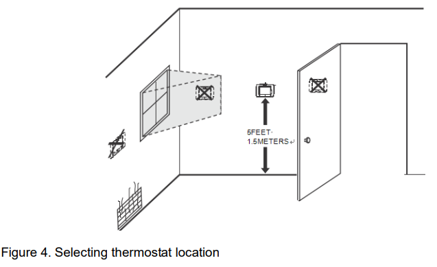
Selecting Location
Install the thermostat about 5 feet (1.5m) above the floor in an area with good air circulation at average temperature. See Figure 4. Do not install the thermostat where it can be affected by:
- Drafts or dead spots behind doors and in corners.
- Hot or cold air from ducts.
- Radiant heat from sun or appliances
- Concealed pipes and chimneys.
- Unheated or uncooled areas such as an outside wall behind the thermostat.
Mounting Means
Mounts directly on the wall in the living space using mounting screws and anchors provided.
Dimensions
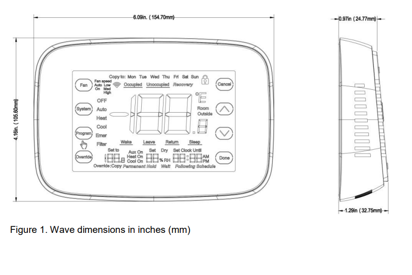
- Wave dimensions: see Figure 1.
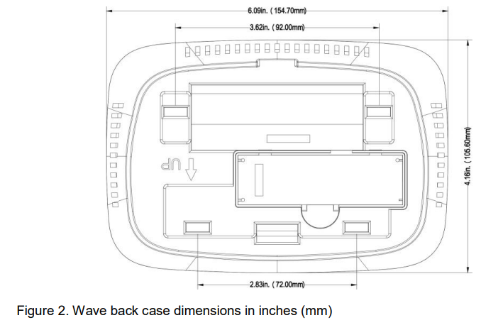
- Wave back case: see Figure 2.
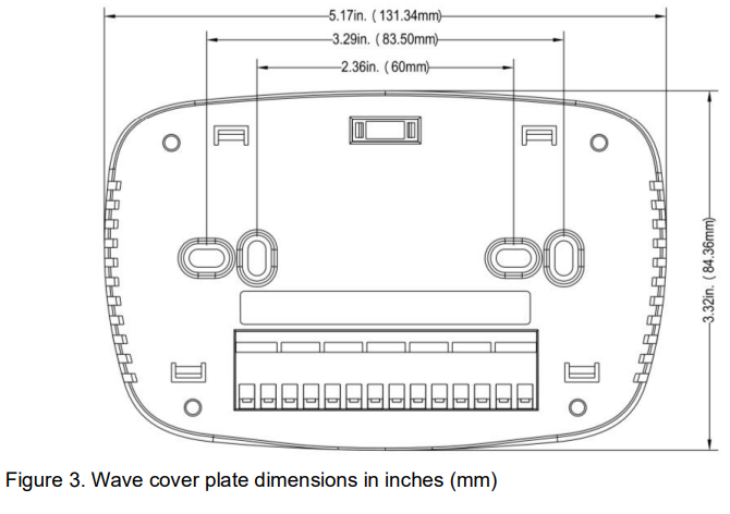
- Wave cover plate: see Figure 3.
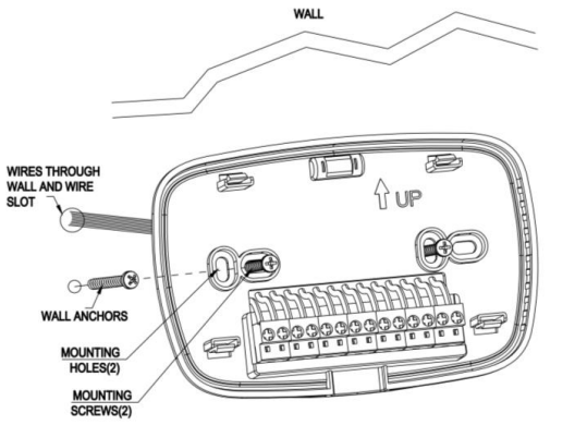
Installing Wall Plate
CAUTION: Electrical hazard can cause electrical shock or equipment damage. Disconnect power before wiring.
The thermostat can be mounted horizontally on the wall.
- Position and level the wall plate (for appearance only).
- Use a pencil to mark the mounting holes.
- Remove the wall plate from the wall and drill two holes in the wall as marked. If necessary, use the provided anchors by gently tapping them into the drilled holes until flush with the wall.
- Position the wall plate over the holes, pulling wires through the wiring opening. See Figure 5.
- Insert the mounting screws into the holes and tighten.
WIRING
All wiring must comply with local electrical codes and ordinances.
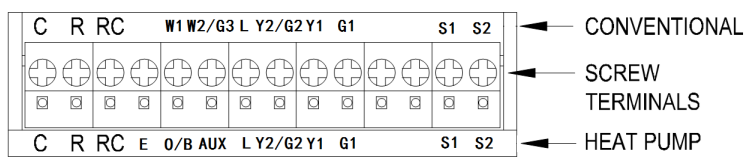
- See Table 1 and Figure 6 for terminal designation descriptions.
- Insert wires in the terminal block under the loosened screw. See Figure 7.
- Securely tighten each screw.
- Push excess wire back into the hole.
- Plug the hole with nonflammable insulation to prevent drafts from affecting the thermostat.
| Terminal Designation | Description |
| RC (see Note 1) | Power for cooling – connect to secondary side of cooling system transformer |
| R (see Note 1) | Power for heating – connect to secondary side of heating system transformer |
| C (see Note 2) | Common wire from secondary side of heating system transformer |
| Y1 | Compressor contactor |
| G1 | Fan relay or low fan speed |
| Y2/G2 | Second stage cooling or medium fan speed |
| O/B/W1 (see Note 3) | Changeover valve for heat pump systems or heat relay |
| W2/AUX/G3 | Auxiliary heat relay for heat pump systems, 2nd stage heat relay, high fan speed |
| E | Emergency heat relay for heat pump systems |
| L (see note 4) | Equipment monitor for heat pump systems |
| S1, S2 | External temperature sensor |
NOTES
- If used in single-transformer system, leave metal jumper wire in place between RC and
R. In two-transformer system, remove metal jumper wire between RC and R. - In a two-transformer system, connect the common from the secondary side of the heating system transformer.
- If thermostat is configured for a heat pump system, configure changeover valve for cool or heat.
- L terminal is an input port as system monitor.
 Terminal identifications for system
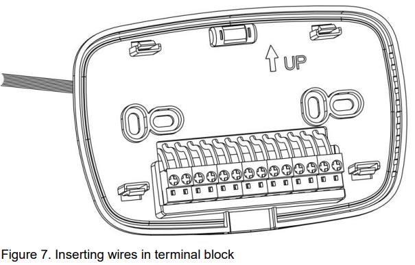
IMPORTANT: Use 18-gauge thermostat wire.
- POWER SUPPLY. PROVIDE DISCONNECT MEANS AND OVERLOAD PROTECTION AS REQUIRED.
- FACTORY INSTALLED JUMPER.
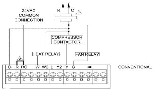
Figure 8. Typical hookup of conventional single-stage heat and cool system with single transformer (1H/1C conventional)
- POWER SUPPLY. PROVIDE DISCONNECT MEANS AND OVERLOAD PROTECTION AS REQUIRED.
- FACTORY INSTALLED JUMPER.
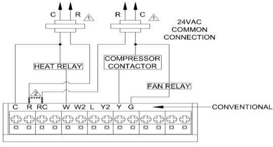
Figure 9. Typical hookup of conventional single-stage heat and cool system with two transformers (1H/1C conventional)
- POWER SUPPLY. PROVIDE DISCONNECT MEANS AND OVERLOAD PROTECTION AS REQUIRED.
- FACTORY INSTALLED JUMPERS.
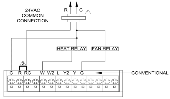
Figure 10. Typical hookup of heat only system with fan (1H conventional)
- POWER SUPPLY. PROVIDE DISCONNECT MEANS AND OVERLOAD PROTECTION AS REQUIRED.
- FACTORY INSTALLED JUMPER.
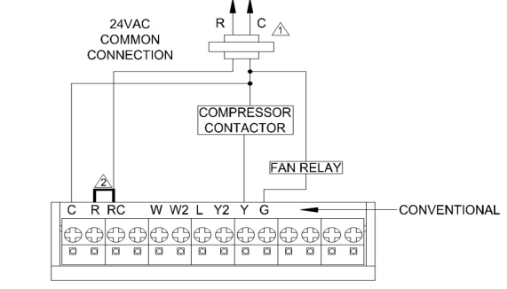
Figure 11. Typical hookup of cool only system (1C conventional)
- POWER SUPPLY. PROVIDE DISCONNECT MEANS AND OVERLOAD PROTECTION AS REQUIRED.
- FACTORY INSTALLED JUMPER.
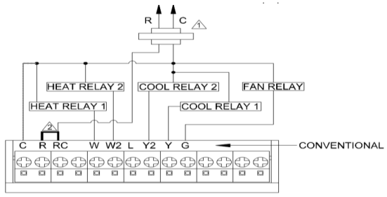
Figure 12. Typical hookup of conventional multistage two-stage heating and two-stage cooling in a single-transformer system (2H/2C, 2H/1C or 1H/2C conventional)
- POWER SUPPLY. PROVIDE DISCONNECT MEANS AND OVERLOAD PROTECTION AS REQUIRED.
- FACTORY INSTALLED JUMPER.
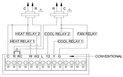
Figure 13. Typical hookup of conventional multistage two-stage heating and two-stage cooling in a two-transformer system (2H/2C, 2H/1C or 1H/2C conventional)
- POWER SUPPLY. PROVIDE DISCONNECT MEANS AND OVERLOAD PROTECTION AS REQUIRED.
- FACTORY INSTALLED JUMPER.
- “O/B” TERMINAL SET TO CONTROL AS EITHER “O” OR “B” IN THE INSTALLER SETUP.
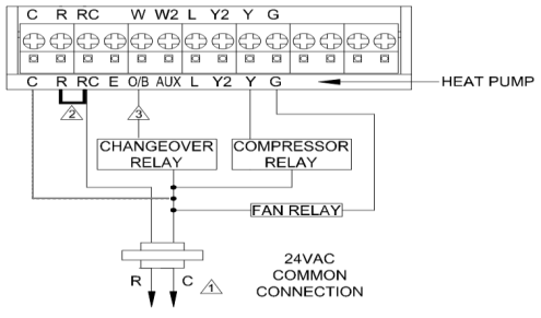
Figure 14. Typical hookup of single-stage heat pump with no auxiliary/backup heat (1H/1C heat pump)
- POWER SUPPLY. PROVIDE DISCONNECT MEANS AND OVERLOAD PROTECTION AS REQUIRED.
- FACTORY INSTALLED JUMPER.
- MUST CONNECT THE 24VAC COMMON WHEN USING L. THE TERMINAL IS SHOWN AS EQUIPMENT MONITOR.
- “O/B” TERMINAL SET TO CONTROL AS EITHER “O” OR “B” IN THE INSTALLER SETUP.
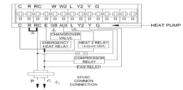
Figure 15. Typical hookup of single-stage heat pump with auxiliary/backup heat (2H/1C heat pump)
- POWER SUPPLY. PROVIDE DISCONNECT MEANS AND OVERLOAD PROTECTION AS REQUIRED.
- FACTORY INSTALLED JUMPER.
- MUST CONNECT THE 24VAC COMMON WHEN USING L. THE TERMINAL IS SHOWN AS EQUIPMENT MONITOR.
- “O/B” TERMINAL SET TO CONTROL AS EITHER “O” OR “B” IN THE INSTALLER SETUP.
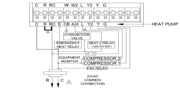
Figure 16. Typical hookup of multistage heat pump with auxiliary/backup heat (3H/2C heat pump).
POWER THE THERMOSTAT
Wiring 24VAC Common
- Single-Transformer System
- Connect the common side of the transformer to the C screw terminal of the thermostat wall plate. Leave the metal jumper wire in place between RC and R.
- Two-Transformer System
- Connect the common side of the heating transformer to the C screw terminal of the thermostat wall plate. Remove the metal jumper wire between RC and R.
Mount Thermostat to Wall Plate
Align the terminal screw blocks with the pins on the back of the thermostat. Push the thermostat straight onto the wall plate until it snaps into place. See Figure 17.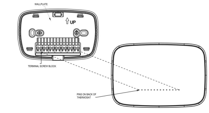
INSTALLER SETUP
Follow these steps to enter the Installer Setup:
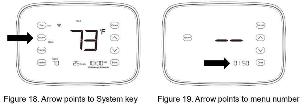
- Press and release the
 key. See Figure 18. System mode will blink.
 - Press and hold the key for approximately 5 seconds until the menu number is displayed in the bottom right corner. See Figure 19.
- Press
 key to view the submenu, and press key to enter the submenu. Under submenu, useset parameters. See Figure 20.
Note: See Table 2 for Installer Setup Menu and Table 3 for Settings.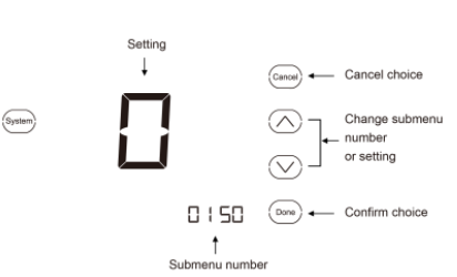
- Press
 key to exit and confirm the installer setup, or press
  to exit without saving changes.
| Number | Name | Settings | Notes |
| 0140 | Version | ||
| 0150 | Date and time | Set calendar date and time | |
| 0160 | Schedule
options |
0: Non-programmable
1: 7-day programmable |
The schedule setting will default
if changed. |
| 0170 | System type selection | 1: Heat only, conventional, with fan (default) 2: Cool only, conventional
4: Single stage heat and cool, conventional 5: Single stage heat and cool, conventional, multi-speed fan 6: Single stage heat pump with AUX heat 7: Single stage heat pump with emergency heat |
Available options and defaults vary by thermostat. System selection automatically modifies some default settings and/or hides other Installer Setup options. |
| Number | Name | Settings | Notes |
| 0170 | System type selection | 8: Single stage heat pump with AUX and emergency heat
9: 2-stage heat and cool, conventional 10: 2-stage heat pump with AUX heat 11: 2-stage heat pump with emergency heat 12: 2-stage heat pump with AUX and emergency heat |
Available options and defaults vary by thermostat. System selection automatically modifies some default settings and/or hides other Installer Setup options. |
| Number | Name | Settings | Notes |
| 0180 | Fan control in heating | 0: Electric furnace thermostat controls fan in heating (factory setting)
1: Gas or oil furnace equipment controls fan in heating |
Only shown if conventional system (except cool-only system) is selected. If heat pump is chosen, fan defaults to
electric. |
| 0190 | Changeover valve O/B terminal energized in heating or cooling (heat
pumps only) |
0: Changeover valve O/B terminal is energized in cooling
1: Changeover valve O/B terminal is energized in heating |
Only shown if heat pump system is chosen |
| Number | Name | Settings | Notes |
| 0200 | Backup heat source
(auxiliary heat) |
0: Heat pump backup heat source is electric (factory setting)
1: Heat pump backup heat source is fossil fuel |
Only applicable in heat pump systems with AUX heating |
| 0220 | Dehumidification
option |
0: Turn off dehumidification
1: Turn on dehumidification |
|
| 0230 | During dehumidification, the max value of temperature can
be set |
Fahrenheit: 1 to 5°F, Default: 3°F Celsius: 0.5 to 2.5°C, Default: 1.5°C | Fahrenheit temperature is 2 times larger than Celsius temperature. Only applicable in dehumidification mode. |
| 0240 | External temperature
sensor option |
0: No sensor (default)
1: Outdoor temperature sensor 2: Remote sensor, report only |
| Number | Name | Settings | Notes |
| 3: Remote sensor, disable thermostat sensor 4: Indoor sensor
5: Occupancy input (dry contact) 6: Float switch input (dry contact) 7: Dry contact input |
|||
| 0250 | Fan Type | 1: Single speed fan
2: Two speed fan 3: Three speed fan |
Only applicable in multi-speed fan type |
| 0260 | High balance
point set range |
Fahrenheit: 23°F to 122°F Celsius: -5°C to 50°C | Only applicable in heat pump
systems with AUX heating and 0240 set to 1 |
| Number | Name | Settings | Notes |
| 0270 | Low balance point set
range |
Fahrenheit: -22°F to 77°F Celsius: -30°C to 25°C | Only applicable in heat pump systems with AUX heating and
0240 set to 1 |
| 0280 | Disable standby
interface option |
0: Disable
1: Enable |
|
| 0290 | Multistage
equipment start timer |
10 to 90 mins Default is 20 mins | Stepping unit is 5 minutes;
applicable in multistage system or multispeed fan system |
| 0300 | Changeover | 0: Manual changeover
1: Auto changeover (default setting) |
| Number | Name | Settings | Notes |
| 0310 | Dead band | 2: 2°F (1.5°C)
3: 3°F (2°C) 4: 4°F (2.5°C) 5: 5°F (3°C) 6: 6°F (3.5°C) 7: 7°F (4°C) 8: 8°F (4.5°C) 9: 9°F (5°C) |
Shown only if automatic changeover is selected |
| 0320 | Temperature indication scale | F: Fahrenheit temperature display (factory setting)
C: Celsius temperature display |
If changed, the schedule will need to be reprogrammed |
| Number | Name | Settings | Notes |
| 0330 | 1st stage temperature
difference |
1°F to 3°F | Fahrenheit temperature is 2 times larger than Celsius
temperature |
| 0340 | 2nd stage temperature
difference |
1°F to 3°F | Fahrenheit temperature is 2 times larger than Celsius
temperature |
| 0350 | 3rd stage temperature
difference |
1°F to 3°F | Fahrenheit temperature is 2 times larger than Celsius
temperature |
| 0360 | Disable cooling
output if outdoor temp |
Fahrenheit: 41°F to 122°F, Default: 50°F Celsius: 5°C to 50°C, Default: 10°C |
| Number | Name | Settings | Notes |
| 0370 | Disable heating output if
outdoor temp |
Fahrenheit: 41°F to 122°F, Default: 77°F Celsius: 5°C to 50°C, Default: 25°C | |
| 0380 | Humidity
Difference |
5 – 20%,Default:5% | |
| 0390 | Occupied
heating set temp |
Fahrenheit: 41°F to 120°F, Default: 68°F
Celsius: 5°C to 49°C, Default: 20°C |
|
| 0400 | Occupied
cooling set temp |
Fahrenheit: 43°F to 122°F, Default: 74°F
Celsius: 6°C to 50°C, Default: 23°C |
|
| 0410 | Unoccupied
heating set temperature |
Fahrenheit: 41°F to 120°F, Default: 68°F Celsius: 5°C to 49°C, Default: 20°C |
| Number | Name | Settings | Notes |
| 0420 | Unoccupied cooling set
temperature |
Fahrenheit: 43°F to 122°F, Default: 74°F Celsius: 6°C to 50°C, Default: 23°C | |
| 0430 | Override time
limit |
30 to 90 mins, Default: 60 mins | |
| 0440 | External sensor compensation
value |
-9°F ~ 9°F (°F as temperature format)
-4.5°C ~ 4.5°C (°C as temperature format) 0°F (0°C) (factory setting) |
|
| 0450 | Override temperature
limit |
2°F – 5°F (°F as temperature format) 0.5°C ~ 2.5°C (°C as temperature format)
5°F (2.5°C) (factory setting) |
| Number | Name | Settings | Notes |
| 0500 | Furnace change reminder | 0: Furnace filter reminder off 1: 10 run time days
2: 30 run time days 3: 60 run time days 4: 90 run time days 5: 120 run time days 6: 365 run time days |
Run time based on call for fan |
| 0530 | Adaptive intelligent recovery | 1: Adaptive intelligent recovery control is activated (system starts early so setpoint is reached by start of program period)
0: Conventional recovery (system starts recovery at programmed time) |
| Number | Name | Settings | Notes |
| 0540 | Number of periods | 2: Two periods available (Wake and Sleep) 4: Four periods available (Wake, Leave, Return and Sleep) | Not shown if non- programmable is selected. Applies to all days of the week. If changed, schedule
must be reprogrammed. |
| 0580 | Minimum compressor
off time |
5: Five-minute compressor off-time setting (factory setting)
0,2,3,4: Other compressor off-time settings |
|
| 0600 | Heat temp
range stop |
41 to 120: Temperature range of heating
setpoint (1°F increments) |
Shown in 1/2 °C |
| 0610 | Cool temp
range stop |
43 to 122: Temperature range of cooling
setpoint (1°F increments) |
Shown in 1/2 °C |
| 0640 | Clock format | 12: 12-hour clock (factory setting)
24: 24-hour clock |
| Number | Name | Settings | Notes |
| 0650 | Extended fan on time heat | 0: No extended fan operation after call for heat ends
90: Fan operation is extended 90 seconds after call for heat ends |
Not shown if 0180 is set to 1 or in cool-only systems |
| 0660 | Extended fan on time cool | 0: No extended fan operation after call for cool ends
90: Fan operation is extended 90 seconds after call for cool ends |
Not shown in heat-only systems |
| 0670 | Keypad lockout | 0: Unlocked keypad
1: Locked keypad 2: All keys locked except Up/Down/Cancel/Done/Override |
Must enter User Setup to unlock keypad |
| Number | Name | Settings | Notes |
| 0680 | ModBus
address |
1 – 32 | |
| 0700 | Temperature display
offset |
-9°F ~ 9°F (°F as temperature format)
-4.5°C ~ 4.5°C (°C as temperature format) 0°F (0°C) (factory setting) |
|
| 0710 | Reset thermostat | 0: No thermostat reset
1: Resets all Installer Setup options to default values and resets schedule to default setting |
Only calendar settings and time are retained |
OPERATION
User Setup
Follow these steps to enter the User Setup:
1. Press and hold the![]() key for approximately 3 seconds until the screen changes. Menu number will be displayed at bottom right corner.
key for approximately 3 seconds until the screen changes. Menu number will be displayed at bottom right corner.
2. Press![]() key to view the submenu, and press key to enter the submenu. Under submenu, use
key to view the submenu, and press key to enter the submenu. Under submenu, use![]() to set parameters.
to set parameters.
3. Press![]() key to exit and confirm the user setup, or press
key to exit and confirm the user setup, or press![]() to exit without saving changes.
to exit without saving changes.
Note: See Tables 3 for the User Setup Settings, and see the Installer Setup chapter for operations reference.
| Number | Description | Settings |
|
0140 |
Version |
|
|
0150 |
Date and time |
Current calendar date and time |
|
0320 |
Display temperature in °F
or °C |
F: °F setting (factory setting)
C: °C setting |
|
0640 |
Clock format |
12: 12-hour clock (factory setting)
24: 24-hour clock |
| 0670 | Keypad Lockout | 0: Unlocked keypad
1: Locked keypad 2: All keys locked except Up/Down/Cancel/Done/Override |
| Number | Description | Settings |
| 0700 | Temperature Display Offset | -9°F ~ 9°F (°F as temperature format)
-4.5°C ~ 4.5°C (°C as temperature format) 0°F (0°C) (factory setting) |
|
0710 |
Reset Thermostat |
0: No thermostat reset
1: Resets all Installer Setup options to default values and resets schedule to default setting |
Date/Time Setting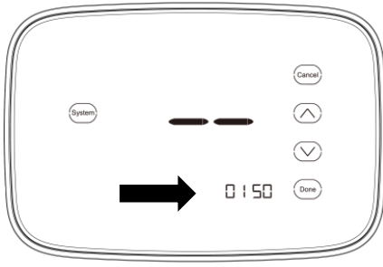
- Consult the User Setup section to enter the User Setup menu. Choose submenu number 0150 to enter the date and time setting. See Figure 23.
- Press to switch the date or time. Options will scroll through in the following order: year, month, day, hour, and minute.
- Pressto adjust the time. You can advance the time more quickly by holding thekey buttons.
- Press to save changes and exit or press to exit without changing the da and time.
Fan Setting
Multispeed fan system
Only single stage heating/cooling systems support the multispeed fan function. In a multispeed fan system: relay G controls fan speed low; relay G2/Y2 controls fan speed mid; relay G3/W2/AUX controls fan speed high. A multispeed fan system supports manual mode and auto mode. Select 0250 in the Installer Setup Menu to set the fan type.
Multispeed fan: manual mode
When the fan is in manual mode, the fan will always be ON. Pressing the FAN button will allow the user to change the speed of the fan. As long as the user has selected LOW, MED, or HIGH, the fan will remain ON and at the set speed. Calls for heating or cooling will not override the fan speed when the upstage timer expires, nor will the fan turn OFF after the desired setpoint is reached.
When in automatic mode, the thermostat must control the fan speed. All calls for heat and cool will use the lowest fan speed by asserting G1. Speed increases will occur if the setpoint for either temperature or dehumidification have not been met after the interval defined by the timed upstage delay period (upstage timer). For two-speed fans, after the timed upstage delay period, G3 will be asserted. For three speed fans, G2 will be asserted. After a second time upstage delay period has passed, G3 will be asserted if the setpoints have not been reached.
Fan selection
Press ![]() to enter fan type selection, ordered in low, mid, high, auto fan mode. Press
to enter fan type selection, ordered in low, mid, high, auto fan mode. Press ![]() to confirm and exit, or press
to confirm and exit, or press ![]() to cancel and exit. Please consult the following figures.
to cancel and exit. Please consult the following figures.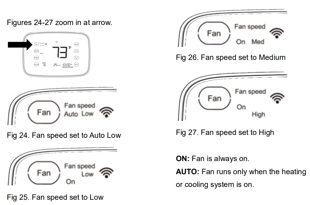
Single speed fan system
Multistage heating/cooling systems do not support the multispeed fan selection. It can only be set to On or auto mode. Details are listed in the fan selection chapter.
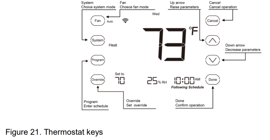
Selecting System Mode
- Press to display options.
- Press again to select an option. You may need to press two or three times to make a selection. The selected option blinks.
- Press to save setting/selection, or press to exit without saving changes.
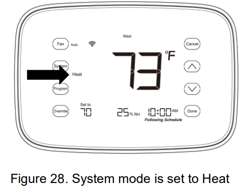
Possible System Modes
- HEAT: Controls only the heating system.
- COOL: Controls only the cooling system.
- OFF: Heating/cooling systems are off.
- AUTO: Selects heating or cooling depending on the indoor temperature.
- EMER (heat pumps with aux. heat): Controls auxiliary/emergency heat. Compressor is locked out. AUTO and EMER system settings may not appear, depending on how your thermostat was installed.
Note: When under auto mode, pressing the![]() key can switch the set temperature between heat and cool.
key can switch the set temperature between heat and cool.
Overrides
Wave has two temperature override options: Override Until and Permanent Hold.
Override Until (temporary override)
Holds temperature temporarily until the next scheduled period time or until time is selected. Setting 0430 in the Installer Setup Menu sets the length of a temporary override. If 0 is chosen, the temporary override will move to the next period.
- Presskey to adjust the temperature to desired setpoint. The icon “Until” appears above the time, and the time indicates the override stop time.
- Press key to exit and confirm the changes, or press to exit without saving changes.
- If you want to exit the Override Until, press the Override button until the icon “Following Schedule” appears under the time.
Holds temperature setpoint permanently.
- Presskey once. The “Until” icon appears above the time.
- Press the Done key.
- Press
 key once. The “Until” icon disappears and the “Permanent Hold” icon appears.
 - Presskey to adjust to desired temperature.
Note: The current day of the week should already be set correctly. If not, see User Setup to set the date and time setting.
Clean Thermostat Screen
Follow these steps to clean the screen without making thermostat changes:
- Press and hold the key for approximately 3 seconds until the screen changes. Thermostat locks out all touch keys for 30 seconds to allow for cleaning. See Figure 29.
- Clean screen using a cloth moistened with water or glass cleaner.
- Press to return to the Home Screen.
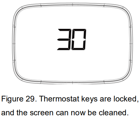
IMPORTANT:
Do not spray liquid directly onto the thermostat. Spray cleaner onto a cloth, then use cloth to clean the screen.
Key Lock
Select 0670 in the User Setup or Installer Setup Menu to set key lock. Key lock includes partial locking or full locking.
Partial locking
In partial locking mode,![]() will appear on display. If user presses locked keys,
will appear on display. If user presses locked keys,![]() will blink to remind user keys are locked. All keys are locked except up, down, confirm, and control. User can press up and down keys to enter override mode, but temperature set range will be limited. See details in Permitted Setpoint Range chapter.
will blink to remind user keys are locked. All keys are locked except up, down, confirm, and control. User can press up and down keys to enter override mode, but temperature set range will be limited. See details in Permitted Setpoint Range chapter.
Full locking
In full locking mode,![]() will appear on display. If user press locked keys,
will appear on display. If user press locked keys,![]() will blink to remind user keys are locked. See the User Setup section for how to unlock keys
will blink to remind user keys are locked. See the User Setup section for how to unlock keys
Setting Filter Reminder Intervals
If activated during installation, the filter reminder flashes “Filter” on screen when it is time to replace your filter. To change the reminder interval:
- Press and hold the key for approximately 3 seconds until the screen changes.
- Pressto select the desired interval (in days), then press to save and exit, or pressto exit without saving.
- Press for approximately 3 seconds to restart the timer.
Note: System setting function 0500 governs the filter interval maximum. The days are counted as fan run time, so anytime the fan is running, the reminder is counting that time against the number of days selected.
Dehumidification
The thermostat supports basic dehumidification using the cooling mode of the unit. Dehumidification occurs if these conditions are met and signals are present at specific terminals:
- dehumidification control has been enabled on installer settings, and the unit is in COOL mode, and a dehumidification demand exists (RH above setpoint plus RH-Hysteresis band)
The thermostat does not support connection to external or auxiliary humidification or dehumidification units. See Installer Setup Menu settings 0220, 0230, and 0380 for more information.
Control Dehumidification Setting
On the home screen, press![]() key for 3 seconds to enter the humidification setting (shown in Figure 31). The humidification setpoint will be displayed in the position as humidification was being displayed. Press
key for 3 seconds to enter the humidification setting (shown in Figure 31). The humidification setpoint will be displayed in the position as humidification was being displayed. Press ![]() key to change setpoint. Press
key to change setpoint. Press![]() key to confirm and exit; press
key to confirm and exit; press ![]() key to cancel and exit.
key to cancel and exit.
Dehumidification Droop Control
The dehumidification control attempts to control to the user’s humidity setpoint by turning on the air conditioner. In extremely high humidity conditions, the thermostat keeps the air conditioner running (energizing Y and G) for up to 3°F below the temperature setpoint. It does this while trying to achieve the desired humidity setpoint and balancing that with the temperature setpoint. The thermostat controls up to 3°F below the temperature setting until either the humidity is satisfied or conditions change. After enabling the dehumidification function, “Dry” will blink on the display. See Figure 32.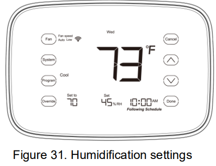
Upstage Timer
This value will be used when determining when to turn the second stage ON (multistage configurations), turning the auxiliary heat ON (heat pump configurations), and increasing fan speed (multispeed fan configurations). See 0290 in the Installer Setup Menu. Examples:
- For a multi-stage heating and cooling system with a 20-minute upstage timer, if the system calls for cooling and it has not reached the desired setpoint after 20 minutes AND the current temperature is greater than [Setpoint plus Second Stage Hysteresis], the second stage compressor will turn ON.
- For a multi-speed fan system with a 20-minute upstage timer, if the system calls for heating and it has not reached the desired setpoint after 20 minutes, the fan speed will be increased (2-speed system from LOW to HIGH, 3-speed system from LOW to MED). On a 3-speed system, if the temperature still has not reached the desired setpoint after 20 minutes (40 minutes after the system starts conditioning the space), the fan speed will be increased from MED to HIGH.
Permitted Setpoint Range
The thermostat provides the ability to limit the range of values a user can select for desired temperature setpoints (Heat, Cool, Occupied Heat, Occupied Cool). This value works in conjunction with the Keypad Lockout settings. When the Keypad Lockout is configured to “All Keys Locked Except Up/Down” AND the permitted range variable is set to a value other than zero (0), the thermostat limits the user to changing the desired setpoint by plus/minus (+/–) the permitted setpoint value.
As an example, if the Keypad Lockout setting is “All Keys Locked Except Up/Down” and the Permitted Setpoint Range is five (5), the user can adjust the current COOL or HEAT setpoints by + or 5 degrees.
Balance Point Control
When a remote sensor is connected and the thermostat is configured for heat pump with emergency or auxiliary heat, the Y1 relay should lock out (prevent from being asserted) when the outdoor temperature is at or below the low balance point, and the W2 relay should lock out (prevent from being asserted) when the outdoor temperature is at or above the high balance point. See 0260 and 0270 in the Installation Menu.
Low Balance Point
If the outside temperature is below the programmed low balance point (set by default at 25°F), compressor operation is not allowed. Since the heat pump is not as effective at a lower outdoor temperature, it may be more comfortable to use the auxiliary electric heat or the furnace (in dual fuel systems, it may be more economical) to satisfy a demand for heat.
High Balance Point
If the outside temperature is above the programmed high balance point (set by default at 50°F), auxiliary electric heat operation or furnace operation (in dual fuel system) is not allowed. This ensures that the lower cost heat pump operation will satisfy the heating demand, rather than the more expensive auxiliary electric heat. The high and low balance points will not lock out both the compressor and the auxiliary heat/furnace at the same time
Remote Sensor
Select 0240 in the Installation Menu to set external sensors. Details are listed in the Installation Setup chapter.
Outdoor Temperature Sensor
If 0240 is set to “outdoor temperature sensor” and the outdoor temperature sensor is installed, pressing the Cancel key will display the remote sensor temperature. Ten seconds after pressing the Cancel key, the display will revert to the thermostat temperature sensor. Additionally, the outdoor temperature is used for enabling high/low balance point function (see Balance Point Control chapter) and for blocking cooling/heating output.
Report Only
If 0240 is set to “report only” and the outdoor temperature sensor is installed, pressing the Cancel key will display the outdoor temperature. Ten seconds after pressing the Cancel key, the display will revert to the thermostat temperature sensor. The outdoor temperature can only be displayed; no logic input judgement will occur.
Disable Internal Sensor
If 0240 is set to “disable internal sensor” and the outdoor temperature sensor is installed, the outdoor temperature will be displayed in the position where the indoor temperature is displayed. Additionally, the internal temperature sensor will be disabled, and the outdoor temperature will completely replace indoor temperature joining logic output judgement.
Indoor Sensor
If 0240 is set to “indoor sensor” and the outdoor temperature sensor is installed, the mean of indoor and outdoor temperature will replace indoor temperature for display and logic output.
Occupancy Sensor
If 0240 is set to “occupancy sensor,” the thermostat will check the input status of the dry contact sensor, which enables either occupied mode (contact CLOSED) or unoccupied mode (contact OPEN). If occupied mode is enabled, thermostat will replace current temperature setpoint with occupied heating and cooling setpoint for logic output. If unoccupied mode is enabled, thermostat will replace current temperature setpoint with unoccupied heating and cooling setpoint for logic output, and temperature cannot be set via UP and DOWN keys.
Float Switch Sensor
If 0240 is set to “float switch sensor,” the thermostat will check the input status of the dry contact sensor. If the contact is closed, the thermostat will close. If the contact is open, the thermostat will operate normally.
Dry Contact Sensor
If 0240 is set to “dry contact sensor,” the thermostat will check the input status of the dry contact sensor, but output status will not be used for logic control.
ModBus
ModBus port setup is: 9600 Baud, 8 data bits, No parity, 1 stop bit. Choose menu item 0680 in the Installer Setup Menu to set the equipment address. If the ![]() symbol is displayed, connecting to the host was successful. If the
symbol is displayed, connecting to the host was successful. If the ![]() symbol is not displayed, connecting to the host failed.
symbol is not displayed, connecting to the host failed.
PROGRAMMING
|
Schedule |
Time |
Setpoints |
Fan Setting |
|
| Heat | Cool | |||
| Wake | 6:00AM | 68°F (20°C) | 78°F (26°C) | Auto |
| Leave | 8:00AM | 60°F (16°C) | 85°F (29°C) | Auto |
| Return | 4:00PM | 68°F (20°C) | 78°F (26°C) | Auto |
| Sleep | 10:00PM | 60°F (16°C) | 82°F (28°C) | Auto |
Program Heating and Cooling Schedule
Your thermostat can control up to four different schedule periods per day:
- Wake – Period when you awaken and want your home at a comfortable temperature.
- Leave – Period when you are away from home and want an energy-saving temperature.
- Return – Period when you return home and want your home back to a comfortable temperature.
- Sleep – Period when you are asleep and want an energy-saving temperature.
Edit Schedule
- Press
 and the screen will change. See Figures 33 and 34.
 - The time will blink. Press or to adjust the time. Press to turn to next setting.
- The temperature will blink. Pressto adjust the temperature. Press to turn to next time period.
- Repeat steps 2 and 3 until all four times periods have been set.
- Press to turn to next day. Repeat steps 2 and 3 until all seven days of the week have been set.
- Press key to exit and confirm the program setting, or press to exit without saving changes.
NOTE: The Fan setting defaults to auto and cannot be programmed.
Copying a Daily Schedule
After entering a day program, you can copy this into another day to save time when creating a weekly program. For example, to copy Monday’s program to Thursday:
- Select the program for Monday, and complete the steps for setting the schedule. After the temperature is set for Sleep, press . The icon appears on the screen and the icon TUE will blink, indicating that you can select or skip this day. Press to select the day or press to skip.
- To copy the Monday schedule to Thursday, press until the icon THU is blinking. Press to select Thursday, and the THU icon will be solid and the icon FRI will blink. Press and the icon will disappear, and the schedule for Monday will be copied to Thursday.
- To select other days, press when the desired day icon is blinking. Press to skip days. Once all desired days are selected, press .
Reset Schedule
To reset the thermostat schedule to the default setting (as seen in Table 4), press and hold the![]() key for approximately 5 seconds until the screen changes (see Figure 35). Release the
key for approximately 5 seconds until the screen changes (see Figure 35). Release the ![]() key.
key.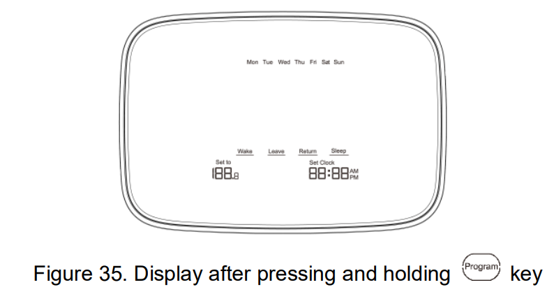
TROUBLESHOOTING
| Symptom | Possible Cause | Action |
|
No LCD display |
Thermostat is not being
powered. |
Check 24VAC between C and R. |
|
Temperature settings do not change. |
Upper or lower temperature limits were reached. |
Check temperature setpoints. Check Installer Setup Numbers
0600 or 0610, modify as needed. |
|
The keypad is fully locked. |
Check Installer Setup Number 0670 to change keypad locked
options. |
|
| Heating or cooling
does not come on. |
Thermostat minimum
off-time is activated. |
Wait up to five minutes for the
system to respond. |
| Symptom | Possible Cause | Action |
| System selection is not set
to Heat or Cool. |
Set system selection to correct
position. |
|
|
System type selection is incorrect. |
Check Installer Setup Number
0170 and make sure correct System type is chosen. |
|
|
Thermostat calls for Heat (Heat on) or Cool (Cool on) but no heating or cooling is running. |
Heating or cooling equipment is not operating. |
Check wiring.
Check Installer Setup Number 0170 and make sure correct system type is chosen. Verify operation of equipment in System Test mode. |
| Symptom | Possible Cause | Action |
| Fan does not turn on in a call for heat
(electric furnace). |
Fan Control in Heating is set to Gas or Oil Furnace
(Setting 0180). |
Set Fan Control in Heating to Electric Furnace (Setting 0180). |
| Heat pump puts out cool air in the heat mode and warm air in
the cool mode. |
Changeover Valve is not configured to match the changeover required by the
installed heat pump. |
Set Changeover Valve (Installer Setup Number 0190) to match the changeover required by the
installed heat pump. |
|
Both the heating and cooling equipment are running at the same time. |
The heating equipment is not a heat pump but the System Type is set to Heat
Pump. |
Set System Type (Installer Setup Number 0170) to match the installed heating and/or cooling
equipment. |
| Heating and cooling wires
are shorted together. |
Separate the shorted heating
and cooling wires. |
| Symptom | Possible Cause | Action |
|
Heating equipment is running in the cool mode. |
Heating equipment is not a heat pump but System Type (Installer Setup Number
0170) is set to Heat Pump. |
Set System Type (Installer Setup Number 0170) to match the installed heating and/or cooling
equipment. |
| Heating equipment does not turn off and heat temperature setting is set below
room temperature |
Heating equipment is not a heat pump but System Type (Installer Setup Number 0170) is set to Heat Pump. |
Set System Type (Installer Setup Number 0170) to match the installed heating and/or cooling equipment. |
| Cannot set the
system setting to Heat or Cool. |
System Type is set to Cool
Only or Heat Only or Heat Only with Fan. |
Set System Type (Installer Setup
Number 0170) to match the installed equipment. |
| Symptom | Possible Cause | Action |
|
Heat On is not in the display. |
System is not set to Heat and/or temperature is not
above room temperature. |
Set the system setting to Heat and set the temperature setting
above the room temperature. |
|
Cool On is not in the display. |
System is not set to Cool and/or temperature is not
below room temperature. |
Set the system setting to Cool and set the temperature setting
below the room temperature. |
|
Wait is in the display. |
Compressor minimum off timer is active. |
Wait up to five minutes for the
cooling or heating (heat pump) equipment to turn on. |
| Screen Locked
appears on screen, keys do not respond. |
The keypad is locked. |
Check Installer Setup Number
0670 to change keypad locked options. |
REFERENCE
DOWNLOAD MANUAL:
Autani 1000172-01 Touchscreen Programmable Thermostat Installation Guide
OTHER MANUALS:
Autani 1000172-01 Wireless Thermostat Quick Installation Sheet
Autani 1000172-01 Wireless Thermostat Product Specification GUIDE

Autani 1000172-01 Touchscreen Programmable Thermostat Installation Guide
Leave a Reply