American Standard AZON1050AC52ZA Programmable Thermostat

ALL phases of this installation must comply with NATIONAL, STATE AND LOCAL CODES
IMPORTANT — This Document is customer property and is to remain with this unit.
These instructions do not cover all variations in systems or provide for every possible contingency to be met in connection with the installation. Should further information be desired or should particular problems arise which are not covered sufficiently for the purchaser’s purposes, the matter should be referred to your installing dealer or local distributor.
Safety
NOTE: Use 18-gauge color-coded thermostat cable for proper wiring. Shielded cable is not typically required.
Keep this wiring at least one foot away from large inductive loads such as Electronic Air Cleaners, motors, line starters, lighting ballasts and large distribution panels.
WARNING This information is intended for use by individuals possessing adequate backgrounds of electrical and mechanical experience. Any attempt to repair a central air conditioning product may result in personal injury and/or property damage. The manufacturer or seller cannot be responsible for the interpretation of this information, nor can it assume any liability in connection with its use. Failure to follow these wiring practices may introduce electrical interference (noise) which can cause erratic system operation.
All unused thermostat wire to be grounded at indoor unit chassis ground only. Shielded cable may be required if the above wiring guidelines cannot be met. Ground only one end of the shield to the system chassis.
WARNING LIVE ELECTRICAL COMPONENTS!
During installation, testing, servicing, and troubleshooting of this product, it may be necessary to work with live electrical components. Failure to follow all electrical safety precautions when exposed to live electrical components could result in death or serious injury.
Product Specifications
| SPECIFICATION | DESCRIPTION |
| Product Model | AZON1050AC52ZA |
| Product | Wi-Fi, AccuLink™ Control with built in Nexia Bridge |
| Size | Product: 7.2” x 4.5” x 1.2”; Display 6.1” x 3.3” (WxHxD) |
| Configurations | Heat Pump, Heat/Cool, Dual Fuel, Heat Only, Cooling Only |
| Maximum Number of Stages | 5 Stages Heat, 2 Stages Cooling |
| Storage/Operating Temperature | -40°F to 175°F, 5% to 95% RH non-condensing |
| Input Power | 24VAC from HVAC System (Range: 18-30 VAC) |
| Power Consumption | 3W (typical) / 4.7W (max) |
| Wire Usage | 18 AWG NEC approved control wiring |
| Communications | AccuLink™ 3-Wire Connection |
| System Modes | Auto, Heating, Cooling, Off, Emergency Heat |
| Fan Modes | Auto, On, Circulate |
| Cooling Setpoint Temperature Range | 60°F to 99°F, 1°F resolution |
| Heating Setpoint Temperature Range | 55°F to 90°F, 1°F resolution |
| Indoor Temperature Display Range | 20°F to 120°F |
| Outdoor Temperature Display Range | -40°F to 135°F |
| Indoor Humidity Display Range | 0% to 99%, 1% resolution |
| Minimum Cycle Off Time Delay | Compressor: 5 minutes, Indoor Heat: 1 minute |
Note: On every application, 24VAC loads should be reviewed to be sure the indoor unit control power transformer is adequately sized.
General Information
Overview
The Platinum1050 Control has a 7 ” color touch screen and offers a full-featured and easy-to-use interface. From individual daily schedules to remote access, the 1050 Control is one of the most advanced Communicating Controls available.
Contents
- 1-1050 Control
- 1-Sub-base
- 4-#6 18X1 Phillips slotted head mounting screws
- 4-Self-tapping wall anchors
- 1-Installation Guide
- 1-Quick Start Guide
- 1-USB “On-the Go” Adapter Cable (Micro USB plug to Standard USB receptacle)
Accessories
- Wired Remote Indoor Sensor (ZZSENSAL0400AA)
- Wired Remote Outdoor Sensor (BAYSEN01ATEMPA)
- Relay Panel for 24v applications (BAY24VRPAC52D)
- Communicating Indoor Temperature Sensor with display (TZONE940AC52ZA)
Zoning Accessories
- Zone Panel Kit (ZZONEPNLAC52ZB)
- Zone Expander (ZZONEEXPAC52ZB)
- Modulating Zone Dampers (round, rectangular and slip-in dampers are available)
Installation
Location
The 1050 Control is designed for installation in climate controlled living spaces. Place the unit in a central location with good circulation.
For proper temperature sensing, avoid exposing the 1050 Control to heat radiated from lamps, sun light, fireplaces or any other radiant heat source.
Avoid locations close to windows, behind doors or alcoves with poor air circulation, adjoining outside walls, or doors that lead to the outside.
Select a location that prevents the 1050 Control from being directly exposed to air currents from supply registers or ceiling fans. Mount the 1050 Control on a section of interior wall that does not contain hot or cold water pipes or duct work.
Important: The 1050 Control utilizes a 7” color touch screen. This screen generates heat which is vented out the top of the 1050 Control utilizing natural convection. If an air source is directed at or from above, the indoor temperature may be biased.
Network Connections
To take advantage of the full range of features on the 1050 Control, it should be connected to the Internet. This is possible using either a wireless or a wired connection.
Wireless Connections
If the 1050 Control will be connected to the Internet using the built-in wireless feature, choose a mounting location that ensures adequate signal strength from the Internet router.
Tips to Help Maximize Signal Strength:
- Mount the 1050 Control within 30 feet of wireless router
- Install 1050 Control with no more than three interior walls between it and the router.
- Locate the 1050 Control where electromagnetic emissions from other devices, appliances, and wiring cannot interfere with system communication.
- Locate the 1050 Control in open areas, not near metal objects, or near structures. (i.e. doors, appliances, entertainment centers or shelving units).
- Locate the 1050 Control further than two inches away from any pipes, duct work, or other metal obstructions.
- Locate the 1050 Control in an area which minimizes metal obstructions and concrete or brick walls between the 1050 Control and the router.
- Refer to the 1050 Control’s User Guide for additional information on connecting to the Internet.
Wired Connections
The 1050 Control may be connected to the Internet using its built-in RJ-45 connector. When using a wired connection, verify that a CAT 5 or better Ethernet cable with a male RJ-45 connector is present from the router to the 1050 Control.
Mounting
Follow these steps to mount the 1050 Control to the wall.
- Turn OFF all power to heating and cooling equipment.
- If an existing thermostat is being replaced:
Remove the existing thermostat from the wall.
Record color and terminal marking of each wire.
Disconnect the wires from the existing thermostat being careful not to allow them to fall back into the wall. - Route the wires through the opening on the Sub-base.
- If using a wired Internet connection, route the Ethernet cable through the opening. See Figures 2 and 3.
- Place the Sub-base against the wall in the desired location and mark the wall through the mounting holes.
- Drill the holes in the wall where marked.
- Mount the Sub-base to the wall using included mounting screws and drywall anchors. For stability, three screws are recommended. Make sure all wires extend through the Sub-base. See Figure 3.


Wiring
- Adjust the length and position of each wire to reach the proper terminal on the connector block of the Sub-base. Strip 1/4” of insulation from each wire. Do not allow adjacent wires to short together when connected. If stranded thermostat cable is used, one or more strands will have to be cut to allow the cable to fit connector. Solid conductor wire larger than 18 ga will not fit the connector.
- Match and connect control wires to the proper terminals on the connector block. Refer to Field Wiring Diagrams included in this document.
- Push excess wire back into the wall and seal the hole to prevent air leaks. NOTE: Air Leaks in the wall behind the 1050 Control can cause improper operation.
- Attach the 1050 Control to the Sub-base.
- Turn ON power to the heating and cooling equipment.
Field Wiring Connection Diagrams


System Setup
Power-Up Sequence
When the 1050 Control is connected to the Sub-base, the 1050 Control initiates a 90-120 second power-up sequence. During the power-up sequence, the Screen Calibration option is available for five seconds (Screen Calibration is available for five minutes if the screen has never been calibrated and following a Restore Factory Defaults command).
If the screen is not pressed within five minutes, the 1050 Control will default to previously stored Screen Calibration settings. The 1050 Control is factory calibrated and can be recalibrated at any time by rebooting the 1050 Control.
Guided Setup Wizards
The 1050 Control features two Setup Wizards, the Installation Wizard and the User Setup Wizard. The Installation Wizard guides installers through the installation and configuration process, and the User Step Wizard guides Homeowners through user-configurable settings.
User Setup Wizard
The User Setup Wizard is accessed navigating to Home>Menu>Settings>User Setup Wizard. By following the navigational steps and screen prompts, homeowners are guided through the Display, Schedules, Guided Schedule, Network, Nexia and Weather configuration screens. Each of these menus may also be accessed individually. Refer to the User Guide for detailed information on user settings.
Installation Wizard
The Installation Wizard appears when the 1050 Control is powered on for the first time, or when the Restore Factory Defaults function is invoked. The Installation Wizard can also be invoked directly in the Service Menu at (Home>Menu>Service>Technician Access>Proceed>Installation Wizard).
By following the navigational steps and screen prompts, installer’s are guided through setting the date and time, completing the installer settings, setting various reminders, and assigning a Dealer Code. Each of these menus can be individually accessed after completing the Installation Wizard.
| INSTALLATION WIZARD MENU ITEMS | DESCRIPTION |
|
Date and Time |
Set the current date, time and select whether Daylight Saving Time is on or off. |
|
Installer Setup |
Configure the basic equipment components installed and customize how the 1050 Control operates. See Installer Setup Screens for detailed information on installer setup options. |
|
Service Reminders |
Various service reminders can be enabled on the 1050 Control based on the system configured. Reminder options are System, Filter, Ventilation, UV Light and Humidifier. The frequency of each reminder can be selected based on calendar or run time days. |
|
Dealer Identification Code |
The dealer identification code is used to populate the Dealer Contact Information and associate this device with a Nexia Dealer Portal account. Enter the primary phone number of the dealership to activate this feature. Only controls connected to the Internet will auto-populate the dealer information. See Section 5.6 for more informatioin |
Installer Setup Screens
From the Installer Setup screens, individual parameters are configured and modified. Use the up and down arrows to scroll through the groups of settings. To change a setting contained in a particular group, press Edit and press Next to navigate to the desired setting. Press Save to save changes or Exit to discard changes.
Group 1 – Standard Settings
| MENU ITEM | OPTIONS [DEFAULT] | DESCRIPTION |
| Outdoor Unit Type | None, Cooling Only, Heat Pump | Select the type of outdoor unit installed |
| Outdoor Unit Stages | Single Stage, Two Stage, Variable | Select the number of outdoor unit stages |
| Compressor Type | Single Compressor Two Stage, Two Compressor Two Stage | Select the compressor type for multi-stage outdoor units |
| Indoor Unit Type | Gas/Oil, Electric, Hydronic | Select the type of indoor unit installed |
| Indoor Heat Stages | 1, 2, 3, Modulating | Select the number of indoor heat stages |
| Indoor Blower Type | Non-Variable, Variable | Select the indoor blower type (Constant Torque motors are considered non-variable speed) |
| * All Group 1 settings will be auto-configured for fully communicating systems. | ||
Group 2 – Zoning Settings
Zoning settings are only available when a Zone Panel is connected and discovered.
Required Steps before enabling zoning:
- Zone Panel must be powered (24VAC transformer)
- Zone Panel must be connected to communicating bus (D, B)
- All non-communicating zone temperature sensors must be connected to corresponding zone slots
- All communicating zone temperature sensors must be addressed to corresponding zone number
- All dampers should be installed and connected to corresponding zone slot
- Discharge Temperature Sensor must be connected
- Differential Static Pressure Sensor and probes should be installed and wired (only required for Auto Zone Sizing)
| MENU ITEM | OPTIONS [DEFAULT] | DESCRIPTION |
| Zoning | Enable [Disable] | Select whether you want to enable zoning |
| Damper Travel Time | 15 – [60] seconds | Select the damper travel time which matches the installed dampers. (All dampers must have the same damper travel time) |
| Auto Detect Dampers | Manual, Auto | Manually select the number of zones or allow the 1050 Control to detect the number of zones installed |
|
Zone Airflow Capacity |
Manual, Auto |
Manually select the percentage of total system air flow each zone can handle (see the table on the next page for manually sizing zones) or allow the 1050 Control to calculate the percentage (Auto selection typically takes 10-12 minutes for up to 4 zones and 20-24 minutes for 5 zones or more)
Theres an additional setting if Auto Detection is selected. Zone Size Adjustment – Normal, Less Aggressive, More Aggressive. Less Aggressive setting results in slightly smaller zone sizes with reduced air flow while More Aggressive setting results in slightly larger zone sizes with increased air flow. |
| % of total | 5-100% for each zone, total must be >100% | Manually input the zone sizes or edit the calculated zone sizes. The sumof the zone sizes must be 100% or greater for zoning to proceed. See the Manual Zone Sizing table on the following page.. |
|
Voting Zones |
Select from assigned zones |
Select which zones are Voting zones. Zones sized 25% or less are forced to non-voting zones. Only voting zones are allowed to call for heating or cooling operation. Non-Voting zones will receive capacity only when a voting zone is also requesting capacity. |
| Indoor Heating Airflow Offset
% (above and below cooling airflow) 1 |
-50% – 50% [0%] |
The air flow offset is the difference between the design cooling air flow (CFM per ton x outdoor unit tonnage) versus the design heating air flow (max heating air flow setting). The 1050 Control uses this offset to calculate and manage excess air. |
| Clamp LV for Auxiliary Heat 2 | Disable, Enable | Select whether to clamp the system load value based on the sumof the calling zones sizes to limit auxiliary heat operation. |
| Auxiliary Heat Threshold 2 | 25 – 99% | Select the threshold which allows auxiliary heat operation when the sumof the zone sizes exceeds the selected threshold. |
| Discharge Temperature Limit
3 – Cooling |
[Normal (38°F)], Extended (34°F) | Select the minimum discharge temperature allowed during cooling operation |
| Discharge Temperature Limit 3
– Compressor Heating Only |
[Normal (116°F)], Extended (128°F) | Select the maximum discharge temperature allowed during compressor heating only operation |
| Discharge Temperature Limit
– Compressor Heating w/Aux Heat 3 |
[Normal (160°F)], Extended (170°F) | Select the maximum discharge temperature allowed during compressor heating with auxiliary heating operation |
| Heating Fuel Type | [Gas], Oil | Select heating fuel type |
| Discharge Temperature Limit 3
– Gas Furnace Heating |
[Normal (135°F)], Extended (145°F) | Select the maximum discharge temperature allowed during indoor heat only operation |
| Discharge Temperature Limit 3
– Oil Furnace Heating |
[Normal (160°F)], Extended (170°F) | Select the maximum discharge temperature allowed during indoor heat only operation |
| Discharge Temperature Limit 3
– Hydronic Heating |
[Normal (135°F)], Extended (145°F) | Select the maximum discharge temperature allowed during indoor heat only operation |
| 1 This setting only applies to systems with an indoor unit type of Gas/Oil or Electric
2 This setting is only available when the outdoor unit type is configured as VSPD 3 If the discharge temperature exceeds the max/min limits the following occurs: 1) Heating/cooling operation is defeated 2) Indoor blower is cycled ON (VS blower runs at continuous fan speed) and 3) All supply dampers are driven full open
NOTE: Discharge Temperature Limit trips will create an alert (SOP.004.56) and heating/cooling operation is temporarily defeated. Once the discharge temperature is below the max limit and the minimum off time has elapsed, zoning operation will resume and the alert will clear. |
||
MANUAL ZONE SIZING
Auto Zone Sizing is the optimal way to determine the amount of air flow into each zone, but this process is not mandatory. Zone sizes can be set manually using the following guidelines.
EXAMPLE (highlighted below): A 2-zone, 3-ton AC system is configured to move 1200 CFM. Zone 1 has a 12” zone damper and Zone 2 has a 16” zone damper.
The Normal sizing strategy would set Zone 1 at 43% and Zone 2 at 81%. If Zone 1 had two dampers (6” and 10”) the zone size % should be added together (11% & 33%) and set to 44%.

Group 2* – Equipment Settings
If Zoning is enabled, this group will be called Group 3.
| MENU ITEM | OPTIONS [DEFAULT] | DESCRIPTION |
| Compressor Cooling Cycles Per Hour | 2 – 6 Cph [3] | Select # of cycles per hour during cooling operation |
| 1st Stage Compressor Cooling Cycles Per Hour | 2 – 6 Cph [3] | Select # of cycles per hour during 1st stage cooling operation |
| 2nd Stage Compressor Cooling Cycles Per Hour 1 | 2 – 6 Cph [3] | Select # of cycles per hour during 2nd stage cooling operation |
| Compressor Heating Cycles Per Hour | 2 – 6 Cph [3] | Select # of cycles per hour during compressor heating operation |
| 1st Stage Compressor Heating Cycles Per Hour | 2 – 6 Cph [3] | Select # of cycles per hour during 1st stage compressor heating operation |
| 2nd Stage Compressor Heating Cycles Per Hour 1 | 2 – 6 Cph [3] | Select # of cycles per hour during 2nd stage compressor heating operation |
| Indoor Heater Cycles Per Hour | 2 – 6 Cph [5] | Select # of cycles per hour during indoor heat operation |
| 1st Stage Indoor Heat Cycles Per Hour | 2 – 6 Cph [5] | Select # of cycles per hour during 1st stage indoor heat operation |
| 2nd Stage Indoor Heat Cycles Per Hour | 2 – 6 Cph [5] | Select # of cycles per hour during 2nd stage indoor heat operation |
| 3rd Stage Indoor Heat Cycles Per Hour | 2 – 6 Cph [5] | Select # of cycles per hour during 3rd stage indoor heat operation |
| 1 Duty Cycles do not apply to second stage (variable range) of VSPD outdoor units | ||
Group 3* – Sensor Settings
If Zoning is enabled, this group will be called Group 4 .
| MENU ITEM | OPTIONS [DEFAULT] | DESCRIPTION |
|
Select Outdoor Temperature Sensor |
No ODT Sensor Thermostat ODT Sensor
Communicating ODT Sensor Relay Panel ODT Sensor |
Select the desired outdoor temperature sensor |
|
Thermostat Humidity Sensor 1 |
Enable, Disable |
Allows the user to re-enable the on-board humidity sensor of the 1050 when a wired sensor is being used in place of the on-board temperature sensor of the 1050 |
|
Humidity Controlling Zone 2 |
Select a zone |
Select which zone’s humidity reading will be the humidity controlling zone. Only zones which have a temperature/humidity sensor can be selected |
| 1 This setting is only available when the onboard temperature sensor has been disabled
2 This setting is only available when zoning has been enabled and one or more 940’s are being used as zone sensors |
||
Group 4* – Accessories Settings
If Zoning is enabled, this group will be called Group 5.
| MENU ITEM | OPTIONS [DEFAULT] | DESCRIPTION |
|
Filtration Type Installed |
[No Comm Air Cleaner Discovered], Comm Air Cleaner Discovered Air Cleaner, [Media Filter] |
Select the filter type installed |
| Number Of Air Cleaners installed | [1], 2 | Select the number of Comm Air Cleaners installed |
| Humidifier Installed 1 | [No], Yes | Select whether a humidifier is installed |
| Humidifier Type | [Powered/Bypass], Steam | Select what type of humidifier is installed |
|
Humidifier Control |
[RH Control], Frost Control |
Select how the humidifier will be controlled (Outdoor temperature sensor must be connected and enabled to allow this setting to be selected) |
|
Humidifier Fan Action |
[Humidify with Active Heat Call], Humidify without Active Heat Call | Select when the humidifier is allowed to operate (Humidification is disallowed during cooling mode or when the System Mode is Auto but the last call was cooling) |
| Airflow During Humidifier Only Mode | 35% – 100% [50] | Select the desired airflow when the humidifier is operating without an active call for heat |
| UV Light Installed 1 | [No], Yes | Select whether a UV Light is installed |
| Ventilation Installed 1 | [No], Yes | Select whether a ventilation system is installed |
| Ventilation – Select Aux Contact | Aux 1, Aux 2 | Select which set of aux contacts is controlling the ventilation system |
|
Outdoor Temperature Ventilation Override |
[Disable], Enable |
Select whether an outdoor temperature override is allowed (Outdoor temperature sensor must be connected and enabled to allow this setting to be selected) |
| Ventilator Fan Action | [Ventilate with Blower], Ventilate without Blower | Select whether the indoor blower operates on a call for ventilation |
| Ventilation – Minimum Outdoor Temperature | -10°F – 50°F [0°] | Select the minimum outdoor temperature that ventilation is allowed |
| Ventilation – Maximum Outdoor Temperature | 80°F – 110°F [100°F] | Select the maximum outdoor temperature that ventilation is allowed |
| Minimum Ventilation Runtime | 0 – 60 Minutes [5 Minutes] | Select the minimum runtime per hour for ventilation system |
| Accumulate Overridden Runtime | [No], Yes | Select whether the overridden ventilation runtime will be made up |
|
Accumulate Period |
[4 hrs -recover based on OD conditions],
24 hrs – recover based on OD conditions, 4 hrs – recover to maintain min ventilation, 24 hrs – recover to maintain min ventilation |
Select when to recover missed ventilation runtime due to outdoor conditions exceeding the minimum/maximum outdoor temperate for ventilation (The first two options will not meet AHRAE 62.2 standard for minimum ventilation requirements) |
| Dehumidifier Installed | [None], Yes | Select whether a dehumidifier is installed |
| Dehumidifier – Select AUX Contact | Aux 1, Aux 2 | Select which set of aux contacts is controlling the dehumidifier |
| Dehumidifier Control Options | [Stand Alone Operation], With Call for Clg Only | Select control of Dehumidifier |
| Run System Fan With Dehumidifier Request | [Yes], No | Select whether the indoor blower operates with a call for dehumidification |
| 1 Requires Relay Panel
2 Only one method of recovery can be enabled. |
||
Group 5* – Comfort Settings
If Zoning is enabled, this group will be called Group 6.
| MENU ITEM | OPTIONS [DEFAULT] | DESCRIPTION |
| Enable Dehumidification | [Enable], Disable | Select if enhanced dehumidification features are enabled. |
| Dehumidification Overcooling Limit – Degrees 1 | [0°] – 3°F | Select the maximum amount of overcooling allowed when the indoor humidity exceeds the cooling target humidity setpoint. |
| Smart Continuous Fan | Enable, [Disable] | Select to enable or disable Smart Continuous Fan. |
| Control Response Rate | [Normal], Fast | Select the response rate of the control. |
| Aggressive Recovery 2 > 2° Setpoint Change | Enable, [Disable] | Select whether the 10-minute staging inhibit is disabled (heating or cooling mode) with a setpoint change greater than 2°. |
|
Heating Aggressive Recovery 2 by Outdoor Temperature |
Enable, [Disable] |
Select whether the 10-minute staging inhibit is disabled during heating mode when the outdoor temperature falls below the selected outdoor temperature (Outdoor temperature sensor must be connected and enabled to allow this setting to be selected). |
| Heating Aggressive Recovery 2
Setting |
0° – 70°F [40°F] | Select the outdoor temperature for Heating Aggressive Recovery |
|
Warm Air Discharge 1 |
Enable, [Disable] |
When enabled the indoor airflow will be limited to 80% on a call for heat pump heating. This only applies to heat pump heating with no call for aux heat (An indoor unit with a variable speed blower is required). |
| 1 This feature is not available when zoning is enabled
2 Only one method of recovery can be enabled.
Refer to Section 7 Advanced Operation for additional information on each setting. |
||
Group 6* – Airflow Settings
If Zoning is enabled, this group will be called Group 7.
All air flow settings are disabled when a communicating variable speed system is applied. Set fan delays on the outdoor unit CDA (communicating display assembly).
| MENU ITEM | OPTIONS [DEFAULT] | DESCRIPTION | |
|
VS Blower On Delay – Clg |
[No Delay], Enhanced Mode,
7.5 Minutes @ 80%, 4 Minutes @ 80%, 1 Minute @ 50%, 30 Seconds |
Select the blower on delay for cooling operation
Enhanced Mode is a tiered Blower On Delay for variable speed blowers only (1 minute at 50%, 7.5 minutes at 80%, then 100%) |
|
|
Non VS Blower On Delay – Clg |
[No Delay], 15 Seconds
30 Seconds |
Select the blower on delay for cooling operation |
|
|
VS Blower Off Delay – Clg 1 |
[No Delay],
1.5 Minutes @ 100%, 45 Seconds @ 100%, 30 Seconds @ 50%, 1.5 Minutes @ 50%, 3 Minutes @ 50%, 30 Seconds @ 35% |
Select the blower off delay for cooling operation |
|
|
Non VS Blower Off Delay – Clg |
[No Delay], 30 Seconds,
60 Seconds, 90 Seconds |
Select the blower off delay for cooling operation |
|
|
VS Blower On Delay – Comp Htg |
[No Delay], Enhanced Mode,
7.5 Minutes @ 80%, 4 Minutes @ 80%, 1 Minute @ 50%, 30 Seconds |
Select the blower on delay for compressor heating operation
Enhanced Mode is a tiered Blower On Delay for variable speed blowers only (1 minute at 50%, 7.5 minutes at 80%, then 100%) |
|
|
Non VS Blower On Delay – Comp Htg |
[No Delay], 15 Seconds,
30 Seconds |
Select the blower on delay for compressor heating operation | |
|
VS Blower Off Delay – Comp Htg 1 |
[No Delay],
1.5 Minutes @ 100%, 45 Seconds @ 100%, 30 Seconds @ 50%, 1.5 Minutes @ 50%, 3 Minutes @ 50%, 30 Seconds @ 35% |
Select the blower off delay for compressor heating operation |
|
|
Non VS Blower Off Delay – Comp Htg |
[No Delay], 30 Seconds,
60 Seconds, 90 Seconds |
Select the blower off delay for compressor heating operation |
|
|
Hydronic Heat Blower On Delay |
[No Delay], 30 Seconds,
60 Seconds |
Select the blower on delay for hydronic heating operation | |
|
Hydronic Heat Blower Off Delay 1 |
[No Delay], 30 Seconds,
60 Seconds, 90 Seconds |
Select the blower off delay for hydronic heating operation |
|
| Compressor Low Stage Air Flow% – Comp Clg 1 | 35% – 60% [50%] | Select the 1st stage air flow for a two stage/two compressor unit in cooling mode | |
| Compressor Low Stage Air Flow% – Comp Clg 1 | 55% – [80%] | Select the 1st stage air flow for a two stage/ single compressor unit in cooling mode | |
| Compressor Low Stage Air Flow% – Comp Htg 1 | 35% – 60% [50%] | Select the 1st stage air flow for a two stage/two compressor unit in heating mode | |
| Compressor Low Stage Air Flow% – Comp Htg |
1 |
55% – [80%] | Select the 1st stage air flow for a two stage/ single compressor unit in heating mode |
| 1 This feature is not available when zoning is enabled | |||
Group 7* – Lockout Settings
If Zoning is enabled, this group will be called Group 8.
An Outdoor Temperature Sensor must be enabled for Lockout settings to be selectable.
| MENU ITEM | OPTIONS [DEFAULT] | DESCRIPTION |
|
Quiet Mode |
[Disable], Enable |
Enables the installer to limit system operation (heating and cooling mode) to meet local daytime and nighttime sound requirements, if necessary. |
| Auxiliary Heat Lockout | [Disable], Enable | Enable auxiliary heat lockout (10° minimum separation when enabling auxiliary heat lockout and compressor heat lockout) |
| Auxiliary Heat Lockout Setting | 32°F – 70°F Degrees [45°F] | Select an outdoor temperature to prevent auxiliary heat above the selected outdoor temperature |
|
Compressor Heat Lockout |
[Disable], Enable 4 |
• Enable compressor heat lockout (10° minimum separation when enabling auxiliary heat lockout and compressor heat lockout)
• When Enabled, another setting appears: Compressor Heating (Auto OR Manual). 4 If Manual is selected, you can manually select values. If Auto is selected, then a series of questions appear to help you determine the most efficient switchover point. |
| Compressor Heat Lockout Setting | 5°F – 70°F Degrees [30°F] | Select an outdoor temperature to prevent compressor heating below the selected outdoor temperature |
| Defrost Heater Balance Point (W1) | [Disable], Enable | Enable defrost heater balance point for W1 (only applicable when indoor heat is electric or hydronic) |
| Defrost Heater Balance Point (W1) Setting | 40°F – [55°F] | Select an outdoor temperature to disallow 1st stage of indoor heat during defrost above this temperature |
| Defrost Heater Balance Point (W2) | [Disable], Enable | Enable defrost heater balance point for W2 (only applicable when indoor heat is electric or hydronic) |
| Defrost Heater Balance Point (W2) Setting | 10°F – 50°F [55°F] | Select an outdoor temperature to disallow 2nd stage of indoor heat during defrost above this temperature |
| Defrost Heater Balance Point (W3) | [Disable], Enable | Enable defrost heater balance point for W3 (only applicable when indoor heat is electric or hydronic) |
| Defrost Heater Balance Point (W3) Setting | [5°F] – 45°F | Select an outdoor temperature to disallow 3rd stage of indoor heat during defrost above this temperature |
| Compressor Cooling 1st Stage Lockout 1 | [Disable], Enable | Enable compressor cooling 1st stage lockout |
| Compressor Cooling 1st Stage Lockout Setting 1 | 80°F – [120°F] | Select an outdoor temperature to force the system to 2nd stage compressor cooling |
| Compressor Heating 1st Stage Lockout 12 | [Disable], Enable | Enable compressor heating 1st stage lockout |
| Compressor Heating 1st Stage Lockout Setting 1 | 0°F – [50°F] | Select an outdoor temperature to force the system to 2nd stage compressor heating |
| Furnace Heating 1st Stage Lockout 13 | [Disable], Enable | Enable furnace heating 1st stage lockout |
| Furnace Heating 1st Stage Lockout Setting 1 | 0°F – [50°F] | Select an outdoor temperature to force the system to 2nd stage furnace heating |
| 1 This feature is not available when zoning is enabled
2 This feature is not available if Compressor Heat Lockout is enabled 3 This feature is not available if Aux Heat Lockout is enabled 4 See the “Dual Fuel Calculator” table for additional options when Enabled |
||
Dual Fuel Calculator
| SETTING | OPTIONS | DESCRIPTION |
| Select the type of Auxiliary (Back-up) Heat Installed | Gas Furnace, Oil Furnace | Select your indoor heat type |
| Enter electricity cost in $/kwh | Electricity Cost | Enter what you currently pay per kilowatt of electricity (see most current electric bill for current rate) |
| Select Gas Option | Natural Gas $/therm, Natural Gas $/MCF, Natural Gas $/Gal | Enter what you currently pay for natural gas (see most current gas bill for current rate) |
|
Choose the furnace AFUE rating |
78 – 98 |
Enter the AFUE rating of the installed furnace (If not known, estimate based on the age of the furnace and the venting type. 90% – 98% for furnaces vented with PVC vent, 80% for motor assisted vented furnaces with double-wall metal vent and 50% – 60% for natural draft furnaces.) |
| Choose the Heat Pump HSPF rating | 7.7 – 12 | Enter the HSPF rating of the installed heat pump. (see AHRI ratings) |
| SETTING | OPTIONS | DESCRIPTION |
| Select the type of Auxiliary (Back-up) Heat Installed | Gas Furnace, Oil Furnace | Select your indoor heat type |
| Dual Fuel Guided Wizard | Electricity Cost | Enter what you currently pay per kilowatt of electricity (see most current electric bill for current rate) |
| Dual Fuel Guided Wizard | Fuel Oil Cost | Enter what you currently pay per gallon of fuel oil (see most current oil bill for current rate) |
|
Choose the furnace AFUE rating |
78 – 98 |
Enter the AFUE rating of the installed furnace (If not know estimate based on the age of the furnace and the type of furnace 80% – 85% for enclosed combustion chamber and 70% for open combustion chamber) |
| Choose the Heat Pump HSPF rating | 7.7 – 12 | Enter the HSPF rating of the installed heat pump. (see AHRI ratings) |
Indoor Sensor Setup
The Indoor Temperature Setup screen allows the technician to view, edit and assign the correct temperature sensor for each zone. It is available in the Technician Access menu. On the left side of the screen, Zones will be displayed. On the right side, available sensor will be shown.
IMPORTANT: Installer Setup>Zoning must be done before assigning sensors to zones. All equipment and dampers should already be assigned or discovered .
Assigning Sensors
To assign a sensor to a zone,
- Select the corresponding zone on the left side of the screen.
- Next, select the appropriate sensor on the right side of the screen.
- Press ASSIGN.
The sensor will be assigned to a zone, and it will now appear on the left side.
Multiple sensors (communicating or non-communicating) can be wired or addressed to each zone, but only one sensor can be assigned to a zone. To change the assignment, select the appropriate zone, then select the desired zone sensor and press Apply.
Note – If the 1050 is being used as a zone sensor it must be addressed as Zone 1.
If a wired remote sensor (ZZSENSAL0400A) is connected to the 1050 RS terminals and assigned as the indoor temperature sensor, the onboard temperature sensor as well as the onboard humidity sensor of the 1050 is disabled. The onboard humidity sensor can be re-enabled in the Installer Settings (Installer Setup > Sensors > Thermostat Humidity Sensor settings.
Service Reminders
Reminders can be enabled to trigger a notification when the configured reminder expires and a message will be displayed across the top of the display. The reminder is time-based and can be configured on system run time or calendar days. Reminders can be configured for humidifiers, filters, ventilation systems, UV lights and HVAC system maintenance. The type of reminders available are based on the accessories enabled in the installer settings.
Dealer Code
When an 1050 Control is connected to Nexia, a Dealer Code can be entered to auto-populate the dealer’s contact information and logo. The code is the dealer’s registered phone number listed on ASDealernet. A dealer can upload a logo by selecting Tech Support from the Home page of ComfortSite, then select Dealer Logo Management and upload logo. File size should not exceed 3MB.
Software Updates
To take full advantage of the features and benefits of the 1050 Control, the latest software revision should be installed.
When the 1050 is connected to a Nexia Home Intelligence account, software updates will occur automatically and do not require user intervention.
The software may also be manually updated. This procedure requires a computer with an Internet connection, a USB Flash Drive and the included USB connector.
- From a computer, go to www.AmericanStandardAir. com. From the Products tab, select Thermostat Controls.
- Click on the 1050 Control.
- Scroll down the page and click on Get Software Updates.
- Follow the onscreen notes to download the software to a USB Flash Drive.
- Once downloaded to your Flash Drive, connect Flash Drive to provided USB to Micro USB connector.
- Insert connector to 1050 Control and navigate to the Software Upgrade screen (Menu > Settings > SW Upgrades)
- Follow the onscreen prompts to complete the upgrade process.
Basic Operation – Non-Zoned
PI Control
The 1050 Control uses proprietary control schemes to provide comfort and energy efficiency. The 1050 Control senses indoor temperature and determines capacity needed based on the following parameters:
- Mode of operation
- Proportional Error – distance from setpoint
- Integral Error – Time away from setpoint

Load Value
The 1050 Control uses proportional plus integral error to determine the amount of capacity required. The calculated capacity is displayed as load value. Load Value is a numerical representation of the needed capacity to maintain setpoint. The load value range is dependent on the applied system.
| LOAD VALUE RANGE – HEATING | |
| 0-100 | Single Stage Heat Pump Only |
| 0-200 | Two Stage/VSPD Heat Pump Only |
| 0-200 | Single Stage Heat Pump + 1 Stage Electric/Wet Heat |
| 0-300 | Single Stage Heat Pump + 2 Stage Electric/Wet Heat |
| 0-400 | Single Stage Heat Pump + 3 Stage Electric/Wet Heat |
| 0-300 | Two Stage/VSPD Heat Pump + 1 Stage Electric/Wet Heat |
| 0-400 | Two Stage/VSPD Heat Pump + 2 Stage Electric/Wet Heat |
| 0-500 | Two Stage/VSPD Heat Pump + 3 Stage Electric/Wet Heat |
| 0-100 | Single Stage Indoor Heat Only |
| 0-200 | Two Stage Indoor Heat Only |
| 0-300 | Three Stage Indoor Heat Only |
| 0-175 | Single Stage Heat Pump + 1 Stage Gas/Oil Heat |
| 0-275 | Single Stage Heat Pump + 2 Stage Gas/Oil Heat |
| 0-375 | Single Stage Heat Pump + 2 Stage Gas/Oil Heat |
| 0-275 | Two Stage/VSPD Heat Pump + 1 Stage Gas/Oil Heat |
| 0-375 | Two Stage/VSPD Heat Pump + 2 Stage Gas/Oil Heat |
| 0-475 | Two Stage/VSPD Heat Pump + 3 Stage Gas/Oil Heat |
| LOAD VALUE RANGE – COOLING | |
| 0-100 | Single Stage Compressor |
| 0-200 | Two Stage/VSPD Compressor |
A Load Value of 50 represents a request of 50% demand for single stage cooling units (“Y”) or 50% demand for stage one of multistage cooling units (“Y1”).
A Load Value of 150 represents a request of 100% demand for stage one (“Y1”) and 50% demand of stage two (“Y2”) for multistage cooling units.
Duty Cycles
Indoor temperature control is achieved by duty cycling the equipment when the load value is less than 100% of the current stage of operation. Duty cycles do not apply to variable/modulating region of VSPD outdoor units or modulating furnaces. The duty cycle rate is dependent on the calculated load value.
The duty cycle chart below indicates the number of cycles at 50% load (i.e. LV = 50).
As with all PI-based controls, the indoor temperature will fluctuate above and below the user selected setpoint to maintain comfort in the space. Adjusting the factory set CPH (Cycles per Hour) can affect how tight the 1050 Control operates around the setpoint. The CPH can be adjusted in the Installer Setup>Equipment Settings (2 – 6 CPH)
- Factory default for compressor operation is 3 CPH
- Factory default for indoor heat is 5 CPH
Effects of changing the cycle rates
Lower CPH results in longer run cycles with less cycling but the indoor temperature may deviate above and below setpoint.
Higher CPH results in tighter indoor temperature control but shorter, more frequent cycles.
Overshoot Clamp
The 1050 Control will enforce an “off cycle” anytime the 1050 Control overshoots more than 2.5°F. Once the indoor temperature is within 0.75°F of setpoint an “on cycle” is allowed dependent on load value and minimum off times.
Stage Thresholds
The threshold to allow operation is a Load Value greater than 5 and operation is always terminated with a Load Value less than 1.
Load Value also determines when additional stages of operation are requested. To prevent rapid cycling between stages, a stage threshold is enforced. The stage threshold is dependent on the applied system.
COMPRESSOR STAGING THRESHOLDS

Note: Stage Thresholds do not apply to Variable Speed Outdoor Unit operation.
Stage Inhibits
When the stage threshold is exceeded, a stage inhibit is applied. The stage inhibit calculates the rate of recovery over a 10-minute period and determines if the next stage is required to meet the current demand. If the rate of recovery is great enough, a new 10-minute inhibit is enabled. The 1050 Control will not go to the next stage of operation until it determines that the current stage cannot satisfy the current demand. Stage inhibits only apply between compressor stages and compressor heat to indoor heat. Stage inhibits do not apply to indoor heat stages.
Stage inhibits can be disabled in the 1050 Control Installer Setup>Comfort Settings.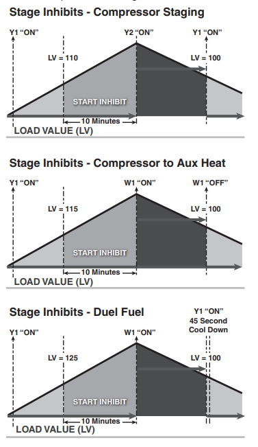
System Mode
The 1050 Control has (5) System Modes which can be selected: Heating, Cooling, Off, Emergency Heat and Auto.
- Heating – System will only operate in heating mode
- Cooling – System will only operate in the cooling mode
- Off – System will not operate in heating or cooling mode
- Emergency Heating – System will operate the indoor heat source only (this is only available when the outdoor unit type is a heat pump)
- Auto – The 1050 Control will determine which mode of operation based on the following rules:
- Heating – Indoor temperature is equal or less than heating setpoint
- Cooling – Indoor temperature is equal to or greater than cooling setpoint or within 1°F of cooling setpoint
There is minimum deadband between heating and cooling setpoints of 3°F (4°F when zoning is applied).
Quiet Mode (VSPD Systems Only)
Quiet Mode limits compressor operation (Heating and Cooling Mode) % Demand to meet local sound requirements. There are two effective times that can be adjusted. Day which starts are 9 AM and Night which which starts at 10 PM which is required in certain jurisdictions. The Quiet Mode feature is available on the 1050 comfort controls.
Charcteristics of Quiet Mode
- When active, the QM symbol will be displayed on the 1050 Home Screen.
- When enabled, Quiet Mode limits both heating and cooling modes.
- Quiet mode may be configured to only limit Day operation, only limit Night operation, or limit Day and Night operation to different % demands.
- Night mode affects operation from 10 PM until 9 AM, at which point Day settings for Quiet Mode take over.
- During heating mode, indoor supplemental heat is allowed if the system cannot maintain space conditions while Quiet Mode is active.
- Local code may require auxiliary heat lockout to be configured.
NOTE: Quiet Mode is disabled by default in the homeowner system options. The option to Disable or Enable Quiet Mode is always available to the homeowner. This functionality is accessed from the Home Screen by pressing System Mode> System Options>Enable on the Quiet Mode option. If Quiet Mode is enabled without installer setup, Night operation allows only the minimum % Demand and Day operation allows maximum % Demand. To optimize Quiet Mode performance, the installing dealer must make the changes to the setup found in the Quiet Mode Set-up document available online.
Fan Mode
The 1050 Control has three Fan Modes:
- Auto – Fan only runs with a call for heating or cooling
- On – Fan runs continuous
- Circ – Fan runs a user selected minimum amount of time each hour
Air Cleaner Mode
The 1050 Control has three Air Cleaner modes:
- Auto – Air cleaner operates only with a call for fan operation
- Quick – Air cleaner will operate for 3-hours with blower at 100%
- Allergy – Air cleaner will operate for 24-hours with blower at 100%
Note: If a communicating Air Cleaner is installed, the power level will be set to High during Quick and Allergy Clean Modes.
Advanced Operation
Control Response Rate
Allows the user to select a set of higher proportional-integral control constants to increase the responsiveness of the 1050 Control. Selecting “Fast” will cause the 1050 Control to generate load value at a faster rate. Control Response rate can be adjusted in Installer Setup>Comfort Settings.
Dehumidification
The 1050 Control utilizes the following methods for dehumidification:
- Air flow reduction (applies only to variable speed blowers) – The 1050 Control can reduce the system air flow by 30% anytime the indoor RH is higher than the cooling RH target. Air flow reduction is disallowed if the indoor temperature is more than 2°F above the cooling setpoint. Dehumidification is factory enabled in the Installer Setup>Comfort Settings.
All “Fan Off” delays are also defeated when dehumidification is enabled and the indoor RH exceeds the cooling RH target. - Overcooling [Disabled when zoning is applied](applies to variable speed and non-variable speed blowers) – If overcooling is enabled, the 1050 Control will allow a 0.1°F of overcooling for each 1% of RH error. A maximum amount of overcooling can be configured for 1°, 2° or 3°F.
-
EXAMPLE OF OVERCOOLING WITH MAXIMUM CONFIGURED AT 2° TARGET HUMIDITY ACTUAL HUMIDITY PERCENT OF RH ERROR DEGREES OF OVERSHOOT 40% 45% 5% 0.5° Overshoot 40% 55% 15% 1.5° Overshoot 40% 65% 25% 2.0° Overshoot 40% 70% 30% 2.0° Overshoot When the system is actively overcooling, Dehumidification will be displayed on the 1050 Control’s home screen. The maximum amount of overcooling is configured in Installer Setup>Comfort settings.
- Smart Continuous Fan (applies to variable speed and non-variable speed blowers) – If enabled, continuous fan operation will be interrupted when indoor RH exceeds desired cooling RH target. A humidity icon will be displayed along with the fan icon to indicate that continuous fan operation has been disabled due to high humidity conditions. Smart Continuous Fan will also interrupt the fan circulate mode when indoor humidity exceeds the desired cooling RH. This feature can be enabled in the Installer Settings>Comfort Settings>Smart Continuous Fan settings.
Dehumidifier Operation
The 1050 Control has the ability to control a Whole-House Dehumidifier through the normally open dry AUX Contacts on the optional Relay Panel. Control options are:
- Stand Alone Operation – Dehumidifier can operate independent from cooling operation as long as the 1050 Control is in Cooling mode or Auto mode and the last call was cooling. When applied with a zoning system, all dampers are driven full open when the dehumidifier is operating without a call for capacity. If Stand Alone Operation is selected, the 1050 Control allows the user to select whether the indoor fan operates with dehumidifier request. For systems with variable speed blowers, the blower speed during a call for dehumidification only will be the same as continuous fan speed
- With Active Call for Cooling Only – Dehumidifier can only operate during an active call for cooling. All dehumidifier control options are located in the Installer Setup>Accessories Settings.
Dual Fuel Operation
The 1050 Control can control a dual fuel system without the need of an external dual fuel kit. An Outdoor Temperature Sensor must be installed and enabled for Restricted Modes to be available. The 1050 Control options are:
- Non Restricted Mode – The 1050 Control will determine which mode of heat will operate to maintain comfort based on the calculated system load value. With a load value in compressor heating range the heat pump will operate and if the load value climbs to auxiliary heat range, the heat pump will cycle off and the auxiliary heat source will cycle on. Once the load value falls below the auxiliary heat range, the auxiliary heat will cycle off, and the heat pump will cycle back on.
- Restricted Mode (compressor heat only) – Once enabled an outdoor temperature lockout can be set to disable compressor heating operation. When the outdoor temperature falls below the compressor heat lockout the system will operate on auxiliary heat source only. At any temperature above the compressor heat lockout the system will operate the same as non-restricted mode, heat pump or auxiliary heat would be allowed based on system load value. Once the compressor heat is locked out, the outdoor temperature must rise at least 4° above the compressor heat lockout setting before allowing compressor heat again.
Restrict Compressor Heat Only
Restricted Mode (compressor and auxiliary heat) –Once enabled an outdoor temperature lockout can be set to disable compressor heating below and disallow auxiliary heat operation above. When the outdoor temperature is above the auxiliary heat lockout, only compressor heat is allowed. When the outdoor temperature falls below the compressor heat lockout, only auxiliary heat is allowed. When the outdoor temperature is between the compressor heat lockout and auxiliary heat lockout the system will operate the same as non-restricted mode, heat pump or auxiliary heat is allowed based on system load value. There is a 10° minimum dead band between the compressor heat lockout and auxiliary heat lockout. Once the compressor heat or auxiliary heat is locked out, the outdoor temperature must rise or fall at least 4°above or below the lockout setting before allowing compressor or auxiliary heat again.
Restrict Compressor and Aux Heat
AN OUTDOOR TEMPERATURE SENSOR MUST BE ENABLED FOR LOCKOUT SETTINGS TO BE AVAILABLE. Lockout options are located in the Installer Setup>Lockout Settings.
Lockouts
The 1050 Control has the following lockouts. AN OUTDOOR TEMPERATURE SENSOR MUST BE ENABLED FOR LOCKOUT SETTINGS TO BE AVAILABLE. Lockouts can be enabled in Installer Setup>Lockout Settings.
- Auxiliary Heat Lockout – Once enabled, select an outdoor temperature which disables auxiliary heat anytime the outdoor temperature is above the selected temperature. Compressor heat will be allowed.
- Compressor Lockout – Once enabled, select an outdoor temperature which disables compressor heat anytime the outdoor temperature is below the selected temperature. Indoor heat will be allowed. NOTE: If enabling Auxiliary Heat Lockout and Compressor Heat Lockout there is a minimum 10°dead band between the two settings.
- Defrost Heater Balance Point (W1) – Once enabled, select an outdoor temperature which disables all electric heat during defrost above the selected temperature.
- Defrost Heater Balance Point (W2) – Once enabled, select an outdoor temperature which disables 2nd and 3rd stages of electric heat during defrost above the selected temperature.
- Defrost Heater Balance Point (W3) – Once enabled, select an outdoor temperature which disables 3rd stage of electric heat during defrost above the selected temperature.
- Compressor Cooling 1st Stage Lockout [Disabled when zoning is applied] – Once enabled, select an outdoor temperature which forces 2nd stage cooling operation.
- Compressor Heating 1st Stage Lockout [Disabled when zoning is applied] – Once enabled, select an outdoor temperature which forces 2nd stage compressor heating operation.
- Furnace Heating 1st Stage Lockout [Disabled when zoning is applied] – Once enabled, select an outdoor temperature which forces 2nd stage furnace heating operation.
Note: If Compressor Lockout is enabled, Compressor Heating 1st Stage Lockout is disabled.
Note: If Aux Heat lockout is enabled, Furnace Heating 1st Stage lockout is disabled.
Humidifier Operation
The 1050 Control has the ability to control a humidifier. Humidification is only enabled while in heating mode of operation. Control options are:
- RH Control – When the indoor humidity is less than the heating target relative humidity, a request for humidification is sent to the indoor unit.
- Frost Control – The 1050 Control references the outdoor temperature and structure integrity to offset the heating target relative humidity. This helps to limit the risk of frost or condensation from forming on interior walls and windows. A scale of 1 to 10 is provided based on the insulation properties and expected leakage of the home (1=Leaky with poor insulation, 10=Very Tight with good insulation). An outdoor temperature sensor must be connected and enabled for frost control to be available.

The 1050 Control can be setup to allow humidification anytime in heating mode or only when actively heating. The airflow during Humidifier-only is factory set to 100% but can be adjusted between 35%-100% (this requires a variable speed indoor blower). All humidifier control options are located in the Installer Setup>Accessories Settings. When zoning is applied, all dampers open fully on a for humidification only.
Stage Inhibits
The 1050 Control utilizes a Stage Inhibit to limit equipment staging. This inhibit can be defeated in the following two manners.
Aggressive Recovery
Greater than 2°Setpoint Change
Disables stage inhibits in heating and cooling mode anytime the setpoint is adjusted more than 2°F
Heating Aggressive Recovery
By Outdoor Temperature Disable stage inhibit in heating mode only when the outdoor temperature falls below the selected outdoor temperature.
Note: If Aggressive Recovery is enabled, Heating Aggressive Recovery is disabled.
Ventilation Operation
The 1050 Control has the ability to control a Ventilation system through the normally open dry AUX Contacts on the optional Relay Panel. The blower can be interlocked on a call for ventilation. The blower speed during a call for ventilation only will be the same as the continuous fan setting for units with a variable speed indoor blower. When zoning is applied, all dampers open fully on a call for ventilation only. The ventilation run time per hour can be adjusted to meet ASHRAE 62.2 standards. A temperature override can be set to prevent ventilation operation when the outdoor temperature exceeds the minimum or maximum outdoor temperature selections. If outdoor temperature overrides are enabled the user can select to accumulate the missed ventilation run time. Options are below:
- Accumulate missed ventilation run time in 4 hour increments and make up when the outdoor temperature is within the min/max settings.
- Accumulate missed ventilation run time in 24 hour increments and make up when the outdoor temperature is within the min/max settings
- Accumulate missed ventilation run time in 4 hour increments and make up at the end of 4 hour period.
- Accumulate missed ventilation run time in 24 hour increments and make up at the end of 24 hour period.
All Ventilation control options are located in the Installer Setup>Accessories Settings.
Warm Air Discharge
[Disabled when zoning is applied] Enabling Warm Air Discharge will reduce the variable speed blower air flow by 20% when in compressor heating operation. Warm Air Discharge only applies to compressor heating and is disabled when hydronic, fossil fuel or electric heat (including supplemental heat) modes are activated. Warm Air Discharge can be enabled in Installer Setup>Comfort Settings.
Wet Heat (Hydronic) Operation
A hot water coil can be applied to either a variable speed or non-variable speed indoor unit. The hot water coil can be the sole source of heat or used as auxiliary heat when applied with a heat pump. When applied with a heat pump, wet heat is considered auxiliary heat and will operate in conjunction with heat pump heat. Switching the system mode to emergency heat would disable the heat pump and cycle the wet heat only.
When using BK to control a variable speed air handler, the blower speed during wet heat only heating will vary based on the system load value. The airflow will range from 35% to 100% depending on the system load value. When applied with a heat pump, the blower speed during heat pump and wet heat operation will be the higher of the two air flows. When not using BK for variable speed blower control, the air handler will determine air flow. There are separate blower “On” and “Off” delays for wet heat in the 1050 Control.
The 1050 Control is designed to operate forced air systems and should not be applied to non-forced air systems (radiant floors, radiators, etc…)
The hydronic heat blower delay options can be accessed by navigating to Installer > Setup > Airflow Settings.
Zoning
Introduction
The 1050 Control is zoning capable with the ability to control single stage, multi stage and variable speed equipment.
The 1050 integrates modulating damper control within system operation without jeopardizing system reliability. The 1050 Control manages excess air by relieving excess air flow into non-calling zones eliminating the need for a bypass damper or position stops in the supply dampers
For optimum performance and comfort, the number of zones should be limited based on the type of system installed.
| RECOMMENDED MAXIMUM NUMBER OF ZONES BASED ON SYSTEM TYPE | ||||
| OUTDOOR UNIT TYPE | COMPRESSOR STAGES | HEATING TYPE | HEATING STAGES | MAXIMUM ZONES |
|
None |
Gas heat | 2 | 4 | |
| Gas heat | Modulating | 6 | ||
| Electric heat | All Stages | 4 | ||
| Oil heat | 1 | 3 | ||
| Hot water | 8 | |||
|
CLG/HP |
1 |
None |
4 | |
| 2 | 4 | |||
| Variable | 8 | |||
|
CLG/HP |
1 |
Electric |
All Stages |
4 |
| 2 | ||||
| Variable | ||||
|
CLG/HP |
1 |
Natural/LP |
2 | 4 |
| 2 | Modulating | 4 | ||
| Variable | 2 | 4 | ||
| Variable | Modulating | 6 | ||
|
CLG/HP |
1 |
Hot Water |
4 | |
| 2 | 4 | |||
| Variable | 8 | |||
|
CLG/HP |
1 |
Oil |
1 | 3 |
| 2 | 1 | 3 | ||
For additional detailed technical zoning information, please refer to Application Guide CNT-APG004-EN.
Zoning Requirements
- 1050 Control
- One Zone Panel is required for up to 4 zones, an optional Zone Expander is needed if more than 4 zones are installed
- Either a communicating or non-communicating zone sensor for each zone
- Power open/power closed fully modulating dampers with a damper travel time between 15 – 60 seconds…60 seconds is the default setting
- Trane or American Standard manufactured indoor unit with a variable speed blower (branded Geothermal package units and oil furnaces are not supported)
- Field supplied 24-volt transformer (transformer should be sized to accommodate all loads connected to Zone Panel)
- Relay Panel would be required if non-communicating HVAC equipment is installed
Operation
When zoning is applied, load value still controls system operation but now each zone will report its own load value.
With zoning each zone will report its own operating parameters:
| OPERATING PARAMETER | DESCRIPTION |
| Requested System Mode | Heating/Cooling/Off |
| Zone Load Value | Capacity required to reach each zone’s requested set point |
| Zone Size | Percentage of total system air flow each zone can handle |
|
Voting Status |
1. Voting zones determine the System Mode and voting zones can request system operation
2. Non-voting zones are only active when a voting zone has requested system operation |
|
Fan Request |
1. Each zone has fan mode option of On or Auto
2. System fan mode determined by last selected zone fan mode 3. When the Fan Mode selected is ON and the system is currently not delivering capacity, all zones dampers are positioned full open |
The 1050 Control uses the parameters above to determine:
Mode of operation
The mode of operation for zoned systems is determined by the following:
- Sum the weighted load value (zone size x zone LV) of all active voting zones (zones with LV > 0) in the same mode of operation
- The higher of the summed weighted LV’s would determine the current mode of operation
- Once operating in any mode, there’s a 15 minute time requirement before allowing a mode change
Example for determining System Mode:
| ZONE 1 | ZONE 2 | ZONE 3 | ZONE 4 | |
| Zone LV | 60 (clg) | 50 (clg) | 60 (htg) | 50 (htg) |
| Zone Size | .30 | .45 | .30 | .65 |
| Weighted LV | 18 | 22.5 | 12 | 32.5 |
| Cooling Sum | 40.5 | |||
| Heating Sum | 44.5 | |||
| System Mode | Heating | |||
Capacity Request (System LV)
System LV is used to determine how much capacity will be requested. System LV is determined by the zone with largest load value in the current mode of operation. See Section 6.2 Load Value for heating and cooling tables for additional information regarding the load value ranges for different systems.
Example for determining System Load Value:
| ZONE 1 | ZONE 2 | ZONE 3 | ZONE 4 | |
| Zone LV | 60 (clg) | 50 (clg) | 80 (clg) | 50 (clg) |
| System LV | 80 | |||
When zoning is applied the System LV may be inhibited for the following reasons:
- The sum of the calling zones is less than or equal to the current stage of capacity (compressor and gas furnace operation only)
- (VSPD systems only) Auxiliary Heat Clamp is enabled and the sum of the calling zones is less than or equal to the clamp setting (Installer Settings>Clamp LV for Auxiliary Heat)
For VSPD systems the speed of the compressor will be limited based on the air flow capacity of the calling zones. Oil return or other protection algorithms may override this clamp
Damper position
The position of the modulating dampers is determined by the amount of capacity each zone is requesting.
The damper position for each same mode calling zone follows the calculation below:
- §Zone LV/ System LV = damper position
The minimum opening position is always 25% to reduce air whistling from a partially opened damper Zones in the opposite or “off” mode are closed unless the system has calculated excess air. Example of how Damper Positions are calculated for non-VSPD and VSPD systems:
| NON-VSPD | ZONE 1 | ZONE 2 | ZONE 3 | ZONE 4 |
| Zone LV | 60 (clg) | 50 (clg) | 40 (clg) | 50 (clg) |
| System LV | 60 | |||
| Damper Position | 100% | 83% | 67% | 83% |
For non-VSPD systems one damper will always be full open on a call for capacity and the other dampers will modulate based on their load value.
| VSPD | ZONE 1 | ZONE 2 | ZONE 3 | ZONE 4 |
| Zone LV | 60 (clg) | 50 (clg) | 40 (clg) | 50 (clg) |
| System LV | 60 | |||
| Scaled System LV | Sytem LV (60) x 1.25 = 75 | |||
| Damper Position | 80% | 67% | 53% | 67% |
For VSPD cooling or compressor heating the scaling of the system load value will result in the dampers being in a less open position than non-VSPD systems. This partial restriction helps maintain static pressure for improved air flow distribution.
Excess Air Management
The 1050 Control manages excess air without the need for bypass dampers, dump zones or position stops in the supply dampers.
The first method of managing excess air is to eliminate or reduce the excess through equipment stage control and air flow modulation
- Equipment Stage Control – For systems with capacity control, the 1050 Control will limit the capacity request based on the sum of the calling zones size…insert chart
- For systems with capacity control, if the sum of the calling zones sizes are less than or equal to the current stage of capacity the system load value will be inhibited disallowing the next stage of operation
- For VSPD systems, the speed of the compressor will be limited based on air flow capabilities of the calling zones. This inhibit may be overridden during oil return mode or if the sum of the calling zones is less than the minimum compressor speed at the current outdoor conditions.
- Air Flow Modulation
The indoor blower speed is controlled based on the type of equipment installed and the air flow capabilities of the calling zones…insert chart
Air flow modulation does not apply during gas furnace heating or electric heat operation.
| COOLING MODE | ||
| System Type | AF Range 1st Stg | AF Range 2nd Stg |
| Single Stg ODU + VS IDU | N/A | 70-100% |
| 2-stg/2-comp ODU + VS IDU | 35-50% | 70-100% |
| 2-stg/1-comp ODU + VS IDU | 55-80% | 70-100% |
| VS ODU + VS IDU | 30% 1 | 31-100% |
| HEATING MODE | |||
| System Type | AF Range 1st Stg | AF Range 2nd Stg | AF Range w/Elect Ht |
| Single Stg ODU + VS IDU | N/A | 70-100% | 100% |
| 2-Stg/2-Comp ODU + VS IDU | 35-55% | 70-100% | 100% |
| 2-Stg/1-Comp ODU + VS IDU | 55-80% | 70-100% | 100% |
| VS ODU + VS IDU | 30% 2 | 31-100% | 100% |
| 2-Stg VS Gas Heat | 65-80% | 100% | N/A |
| Modulating VS Gas Heat | 40% 3 | 413-100% | N/A |
| Electric Heat | N/A | N/A | 100% |
| Hydronic VS Heat | 35% | 36-100% | N/A |
| 1 Minimum air flow percentages may be higher during oil return mode
2 Minimum air flow percentages may be higher during oil return mode or during cold outdoor ambient temperatures 3 45% for 120K models |
|||
If the 1050 Control still calculates excess air, then the excess will be relieved following the rules below:
- Relief Strategy 1
Divide the excess air evenly between the zones which are calling but their dampers are not 100% open - Relief Strategy 2
Divide the remaining excess air evenly between the zones which are in the same calling mode but have zero load value (zones in the “OFF” mode are considered same calling mode zones) - Relief Strategy 3
Divide the remaining excess air evenly between the zones which are in the opposite mode regardless of load value - Note – The minimum damper position when a zone is relieving is 25%.
Relief Strategy
The relief strategy employed by the 1050 successfully manages excess air without affecting the efficiency or reliability of the applied heating/cooling system. Zone(s) may overshoot their setpoint if the system is not applied properly. Common application mistakes which cause zone(s) to overshoot:
- Too many zones applied for the equipment selected
- Disproportionate-sized zones (one large zone and one small zone)
- Zone branch ducts undersized (zone branch ducts should be sized based on the peak load of the rooms in the zone)
Follow the guidelines detailed in the Application Guide CNT-APG003-EN to ensure zoning success.
Diagnostic Tools
Test Modes
Access Test Modes by navigating to Service Menu>Test Modes. All test modes will terminate automatically after 60 minutes or can be terminated manually at any time.
Non-Variable Speed
| MODE | SETTINGS | DESCRIPTION |
| Test Blower | 50%, 100% | Energize indoor blower at the selected speed |
| Test Cool | Stage 1
Stage 2 |
Energize the selected stage of cooling operation. The indoor blower will also operate at the speed required for the selected stage |
| Test Compressor Heat | Stage 1
Stage 2 |
Energize the selected stage of compressor heating operation. The indoor blower will also operate at the speed required for the selected stage |
|
Test Indoor Heat |
Stage 1 Stage 2 Stage 3 |
Energize the selected stage of indoor heating operation. The blower operation will be dependent on the indoor heat type:
Electric – blower energized during test mode but the blower speed is controlled by the indoor unit Fossil – blower is controlled independently by the indoor unit during test mode Hydronic – blower is energized during test mode |
| Test Compressor and Indoor Heat | Stage 1 Indoor Heat Stage 2 Indoor Heat Stage 3 Indoor Heat | Energize all stages of compressor heat and selected stage of indoor electric heat/hydronic heat. The blower is energized and runs at the higher of the compressor heat air flow versus indoor heat air flow |
|
More |
Test Humidifier, Test Aux Contact | Closes the normally open Humidifier/AUX contacts. The blower is not energized during this test mode
Need to see if blower operates during these test modes if blower interlock is enabled. |
Variable Speed
| MODE | SETTINGS | DESCRIPTION |
|
Charging Mode – Cooling |
Test |
Energizes outdoor unit at the correct compressor speed and associated indoor blower speed to set/verify sytem charge. Use sub-cooling tables in the outdoor unit Service Facts to determine correct charge levels. Outdoor temperature must be within 55F to 120F and indoor temperature must be between 70F to 80F. This is the only approved method for charging/verifying system charge on variable speed systems. |
|
Check Charge Mode – Heating |
Test |
Energizes outdoor unit at the correct compressor speed and associated indoor blower speed to compare actual performance to typical performance. Use the pressure curves in the outdoor unit Service Facts for comparison. This method is not an approved method for verifiying the charge on variable speed systems. |
|
Checkout Mode – Cooling |
0-100% |
This test mode allows the user to adjust the cooling compressor speed in selected increments from minimum to maximum. The single arrows represent a 1% change and double arrows a 5% change. This test mode allows the user to troubleshoot noise/ harmonics which may occur at various compressor speeds. |
|
Checkout Mode – Heating |
1 to100% |
This test mode allows the user to adjust the heating compressor speed in selected increments from minimum to maximum. The single arrows represent a 1% change and double arrows a 5% change. The user can also initiate a forced defrost cycle from the test mode screen. This test mode allows the user to troubleshoot noise/harmonics which may occur at various compressor speeds. |
|
Pump Down Mode – Cooling |
Test |
This test mode will pulse the latching switchover valve to cooling position and run at full compressor speed. The outdoor EEV will remain open and the indoor EEV (if installed) will continue to control superheat. |
|
Pump Down Mode – Heating |
Test |
This test mode will pulse the latching switchover valve to heating position and run at full compressor speed. The outdoor EEV will control superheat and the indoor EEV (if installed) will remain open. |
Damper Test Mode
Damper Test Mode gives the user the ability to open specific dampers to verify the dampers are performing properly. Each damper can be driven independently or in any combination. The blower will operate during an active damper test. The blower speed is determined by the sum of the Zone Size’s of each damper selected to be tested. Damper Test Mode will automatically timeout after 30 minutes or immediately if “Stop” is pressed.
Upon entering Damper Test Mode, all system operation will stop and each damper will be driven full open. Once a damper(s) is selected for test, the non-selected dampers will be driven fully closed.
Save Logs
The 1050 Control has the ability to log data on USB Flash Drive. Attach a USB Flash Drive to the included USB connector, plug it into the 1050 Control and select Save Logs from the Service Menu.
Access Save Logs by navigating to Service Menu>Save Logs.
Diagnostics
Alerts
Within the Diagnostic screen are two items related to alerts:
- Current Alerts – Alerts which are currently active
- Alert History – Cleared Alerts (last 30 days)
NOTE: Each alert will have a date/timestamp of when the alert was negated. The Date/Time stamp for Current Alerts is when the alert was asserted. For Alert History the date/timestamp is when the alert was negated.
From both screens the user can select an alert code and get additional information on the alert as well as a list of possible causes, similar to the Interactive Troubleshooting Guide located on ComfortSite/ASDealernet
All alerts are categorized by severity:
- CRITICAL
Loss of heating/cooling operation
Service call is required
Alert messages are displayed on the home screen - MAJOR
Reduced functionality – minimum operation is possible— Service call is not immediately required
Alert messages are not displayed on the home screen - NORMAL
Functionality may be lost but should recover or the information is for diagnostic purposes / performance monitoring
Service call is not required
Normal alerts are only displayed in the Diagnostic screen
Diagnostics can be accessed by navigating to Service Menu>Diagnostics.
Summary Table
The 1050 Control has a Summary Table which lists all the communicating devices that have been discovered. In addition to viewing the status of each communicating device, the Summary Table can be used to remove “offline” devices. The screen is made up of three fields:
- Device Information: Lists the device name and model/serial number
- Enabled: Identifies whether the device has been enabled
- Status: Identifies whether the device is currently reporting on the bus (Only “Offline” devices can be removed)
The Enabled and Status field can be used to troubleshooting/informational purposes:
- Enabled + Online: Device has been enabled and is currently reporting on bus
- Enable + Offline: Device has been enabled but is not reporting (Err.126.00 will typically be triggered during this condition).
- Disabled + Online: Device has not been enabled but is reporting (verify device has been configured in the installer settings).
- Disabled + Offline: Device has not been enabled and is currently not reporting.
History
History is accessed by navigating to Service Menu>History
The History screen allows the technician to view cycle count and a sum of the run time in minutes for each mode and stage of operation. This data provides a snap-shot into system operations.
| SYSTEM HISTORY TABLE | ||||
| TODAY | LAST 7 DAYS | CURRENT MONTH | LAST MONTH | |
| Y1 Cooling | 561/7842 | 2061/24122 | 11881/106922 | 20461/163682 |
| Y2 Cooling | ||||
| Y1 Heating | ||||
| Y2 Heating | ||||
| W1 | ||||
| W2 | ||||
| W3 | ||||
| Defrost Cycles | ||||
| ZONE HISTORY TABLE | ||||
| Relief Cycles | 21/262 | 51/482 | 141/1122 | 191/1372 |
| Cooling over- shoot > 2.5° | 1/– | 4/– | 8/– | 4/– |
| Heating Over- shoot > 2.5° | 0/– | 1/– | 3/– | 6/– |
- Indicates cycle count
- Indicates cycle time in minutes
System Report
The System Report Screen provides technicians with important system operational data in one, concise screen. The data is provided in real-time and updates as the data changes. The tables below show the information available for zoned and non-zoned systems.
Restore Factory Defaults
This feature will delete all saved settings, both user and installer, and restore the 1050 Control to its factory default settings. Z-Wave settings will not be cleared.
| SYSTEM REPORT SCREEN | SYSTEM REPORT SCREEN – ADDITIONS FOR ZONING | |||
| FIELD NAME | DESCRIPTION | FIELD NAME | DESCRIPTION | |
| System Name | Name given to this 1050 Control. | Zone Name | Displays enabled zones | |
| Operation Status | Current mode of operation | Mode | Indicates current mode per zone | |
| Operation Stage | Current stage of operation | Size | Indicates air flow capacity per zone | |
| *Req Capacity | Amount of capacity being requested | Temp | Current indoor temperature per zone | |
| *Delv Comp Spd | Percentage of compressor speed currently operating | Cool | Current cooling set point per zone | |
| Load Value | Numerical value used to determine how much capacity is required to meet set point. For more information see 6.2 Load Value. | Heat | Current heating set point per zone | |
| Air Flow | Current percent of air flow being delivered (this value is only available for indoor units with variable speed blowers operating in cooling or compressor heating operation) | Load | Current load value per zone | |
| **Excess Air | Amount of excess air currently calculated | RH | Current indoor RH per zone | |
| ODT | Current outdoor temperature (requires an outdoor temperature sensor to be con- nected and enabled) | DMP | Current damper position per zone | |
| **Static PSI | Current static pressure being measured | Sensor | Indicates the indoor temperature sensor type per zone | |
| **Return Air Temp | Current temperature of return air | * Only applicable for systems with a VSPD outdoor unit
**Only applicable for zoned systems |
||
| **Discharge Air Temp | Current temperature of supply air | |||
| Humidifier | Indicates current status of humidifier, if installed | |||
| Dehumidifier | Indicates current status of dehumidifier, if installed | |||
| Ventilation | Indicates current status of ventilation sys- tem, if installed | |||
Troubleshooting
| SYMPTOM | POSSIBLE CAUSES | ACTION |
| 1050 Control displays an alert on the screen. | A critical or major alert is present. | Navigate to the Diagnostic screen on the 1050 Control for a Problem Description and Possible Cause. |
| Display will not come on | Loss of 24VAC between R & B at the 1050 Control. | 1) Check wiring between R & B
2) Check transformer for 24VAC output. 3) Check for broken or shorted thermostat wire. |
| Indoor temperature display is incorrect. | 1) Indoor temperature display needs calibration.
2) Surrounding air flow affecting sensed temperature of the 1050 Control |
Calibrate temperature sensor from 1050 Control’s menu. |
| Indoor humidity display is incor- rect. | Indoor humidity display needs calibration. | Calibrate humidity sensor from the 1050 Control’s menu. |
| Room temperature overshoots when the Heat/Cool setting is changed more than 2°. | 1) Oversized heating/cooling equipment under current conditions. 1050 Control cannot re- spond fast enough to prevent overshooting.
2) Improper location of 1050 Control. |
1) Compare heat load calculation to equipment chosen.
2) Relocate 1050 Control (or use remote sensor) |
| Heating will not come on. | 1) System mode is not set to Heat/Auto or set- point is set too low.
2) Minimum off time delay is being enforced. 3) Heating system may require service. |
1) Set mode to heat and raise the setpoint above the room temperature.
2) Wait for 5 minutes and recheck heating equipment. 3) Check/repair system. |
| Cooling will not come on. | 1) System mode is not set to Cool/Auto or the setpoint is too high.
2) Minimum off time delay is being enforced. 3) Cooling system may require service. |
1) Set mode to cool and lower the setpoint below the room temperature.
2) Wait for 5 minutes and recheck cooling equipment. 3) Check/repair system. |
| Heating or Cooling is displayed, but no warm or cool air is coming from the registers. | 1) There is a fan delay as the heating or cooling equipment turns on.
2) Equipment is not working properly. |
1) Wait a minute for blower delays and recheck regis- ters.
2) Check/repair system. |
| Fan runs all the time | 1) Fan mode is set to On, Circulate or Clean mode
2) There is a failure in the indoor unit |
1) Check 1050 Control settings to see if fan is set to On, Circulate or Clean mode.
2) Check indoor unit for failures (such as tripped heat- ing limit). |
| “+” symbol appears on Home Screen beneath Indoor Temperature readout | Both compressor heat and indoor heat are being called simultaneously | No action required, symbol is for informational purposes only |
| Fan is set to ON but not running. | 1) Smart Continuous Fan feature has been is engaged.
2) Blower motor is not functioning. |
1) If indoor humidity is higher than desired setpoint, the blower will cycle off with the equipment. A humidity icon will be displayed on the Fan Mode button when the blower operation is being inhibited due too high humidity.
2) Check/repair system. |
| Cooling or Heating cycles too fast or too slow (narrow or wide temperature swings). | 1) Check the location of the 1050 Control for drafts.
2) Cycles per hour or aggressive recovery is improperly set. |
1) Seal air leaks behind 1050 Control. Relocate 1050 Control or apply remote indoor temperature sensor.
2) Adjust cycle rates and aggressive recovery features in the advanced installer set up. |
| Heat pump is not turning on; only furnace or electric heat strips are running. | 1) Outdoor temperature is below compressor lockout temperature setting.
2) Compressor heating lockout is enabled and outdoor temp sensor is out of calibration or failed. 3) The outdoor unit is not reporting (Err.126.00) |
1) Adjust the compressor lockout temperature setting if desired.
2) Check/repair outdoor sensor or wiring. 3) Check communication status of outdoor unit. |
| SYMPTOM | POSSIBLE CAUSES | ACTION |
| Cannot change system mode to desired setting. | Equipment is not configured properly. | Check the standard installer set up screen to ensure equipment is properly configured. |
| Screen does not respond prop- erly to a button press | 1) Screen is out of calibration.
2) Internal 1050 Control fault 3) Screen Lock has been enabled |
1) Remove 1050 Control from sub base and reset. Follow the calibration instructions when the 1050 Control reboots.
2) Remove 1050 Control from sub base and reset. 3) Press and hold the Menu button for 5 seconds to override screen lock. |
| Screen goes blank after a period time of inactivity | Screen Saver mode set to “Black” which turns of screen back light after a user selected time of inactivity. | Normal operation. User may change screen saver from “Black” to “Indoor Temperature” or increase the time before screen saver is activated. |
| Zoning enable option is not avail- able in the Installer Settings. | Zone Panel is either not installed or installed but not communicating. | Install Zone Panel or verify wiring to Zone Panel. |
| Zoning has been disabled and the system is operating as a non- zoned system | A system alert has occurred which disabled zoning but allows non-zoned operation. | Check for system alerts in the Diagnostics > Current Alerts screen. |
| Time set on 1050 Control changes every 24 hours. | 1050 Control is connected to Nexia and the time zone set on Nexia account is incorrect | Correct the time zone set on Nexia account. |
Notices
FCC Notice
FCC ID: XVRZON1050
INFORMATION TO USER
This device complies with Part 15 of the FCC Rules. Operation is subject to the following two conditions: (1) This device may not cause harmful interference and (2) This device must accept any interference received, including interference that may cause undesired operation. The antenna(s) used for this transmitter must be installed to provide a separation distance of at least 20 cm from all persons and must not be collocated or operating in conjunction with any other antenna or transmitter.
This equipment has been tested and found to comply with the limits for Class B Digital Device, pursuant to Part 15 of the FCC Rules. These limits are designed to provide reasonable protection against harmful interference in a residential installation. This equipment generates and can radiate radio frequency energy and, if not installed and used in accordance with the instructions, may cause harmful interference to radio communications. However, there is no guarantee that interference will not occur in a particular installation. If this equipment does cause harmful interference to radio or television reception, which can be determined by turning the equipment off and on, the user is encouraged to try to correct the interference by one or more of the following measures.
- Reorient or relocate the receiving antenna
- Increase the separation between the equipment and receiver
- Connect the equipment into an outlet on a circuit different from that to which the receiver is connected
- Consult the dealer or an experienced radio/TV technician for help
Any changes or modifications not expressly approved by the party responsible for compliance could void the user’s authority to operate the equipment.
IC Notice
IC: 6178D-ZON1050
This device complies with Industry Canada license-exempt RSS standard(s). Operation is subject to the following two conditions: (1) this device may not cause interference, and (2) this device must accept any interference, including interference that may cause undesired operation of the device.
The manufacturer has a policy of continuous product and product data improvement and it reserves the right to change design and specifications without notice. Representative-only illustrations are included in this document.
Reference
Download Manual:
American Standard AZON1050AC52ZA Programmable Thermostat Installation Guide
OTHER MANUALS;
American Standard AZON1050AC52ZA with NEXIA User Manual
American Standard AZON1050AC52ZA Programmable Thermostat Installation Guide