
AMANA PHWT-A150H Non-Programmable Electronic Thermostat
DESCRIPTION AND COMPATIBILITY
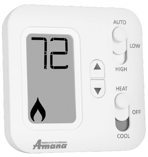
The Amana PHWT-A150H is a non-programmable electronic thermostat, which can be used with the following heating/cooling applications:
- Cooling/ Conventional PTAC Units (PTC) with or without Electric Heat
- Heat Pump PTAC Units (PTH or HEH) with or without Electric Heat
SPECIFICATIONS
- Input Voltage: 19 to 30 VAC
- Output Rating: Max. 1.5A per terminal (3A total)
- Temperature Control: 45°F to 90°F (7°C to 32°C)
- Temperature Accuracy: ± 1°F (± 0.5°C)
- Wire Terminals:
- C: 24 VAC Common
- GL: Fan LOW Speed
- GH: Fan HIGH Speed
- W2: 2nd Stage or Auxiliary Heating Signal
- W1: 1st Stage Heating Signal
- Y: Cooling Signal
- R: 24 VAC Hot
- B/O: Reversing Valve
SAFETY INFORMATION
- This thermostat is for LOW voltage applications only.
- Turn OFF electricity to all heating and cooling components.
- All wiring must conform to applicable local and national building and electrical codes and ordinances.
TO REMOVE EXISTING THERMOSTAT
- Write down the letters printed near each wire terminal that is used, and the color of each wire it is connected to; self-adhesive wire labels are also enclosed.
- Carefully remove wires from existing thermostat and bend so they cannot fall back into wall or touch each other.
- Remove existing thermostat base from the wall.
TO INSTALL NEW THERMOSTAT
- Mount the thermostat on an inside wall aboutfive feet above the floor in an area that has good circulation, but is not directly affected by a vent or duct.
- If painting or construction is still ongoing, cover the thermostat completely or wait until work is complete before mounting thermostat.
- If new mounting holes are needed, mark the placement of the new mounting holes through the thermostat base. Using a 3/16” drill bit, drill the holes you have marked and insert the supplied wall anchors.
- Feed the wires through the wire opening in the base and use supplied screws to mount base to the wall.
- Using Section 7) WIRING DIAGRAMS, wire each terminal on the new thermostat base. Ensure that the bare end is fully seated into the connector, then tighten securely. Pull gently on wires to ensure they are secure.
- Place thermostat front back onto the base.
- Restore power back to heating and cooling components and thermostat.
- See Section 8) INSTALLER SETTINGS MENU, to adjust the required settings needed for each system type.
FRONT PANEL CONTROLS
THERMOSTAT SYSTEM MODE SWITCH POSITIONS
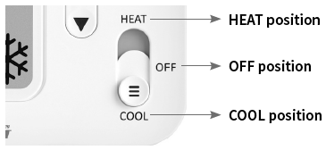
- HEAT = thermostat permits heating operation
- OFF = thermostat stops all heating or cooling functions
- COOL = thermostat permits cooling operation
THERMOSTAT FAN SWITCH POSITIONS
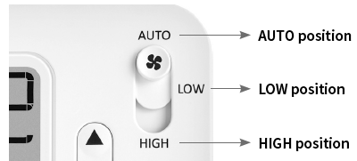
- AUTO position = fan operates in low speed mode as needed during a call for heating or cooling activation only.
- LOW position = fan operates continuously in LOW speed, with the heating or cooling components cycling on and off in the background as needed.
- HIGH position = fan operates continuously in HIGH speed, with the heating or cooling components cycling on and off in the background as needed.
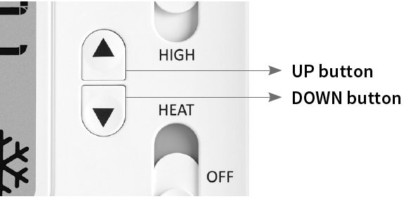
- UP / DOWN = used for raising or lowering the target set temperature and selecting user options and settings in the display screen.
The temperature that is shown at all times in normal operation is the Target Set Temperature. To view current ambient room temperature while in Heat or Cool mode, perform a single press of BOTH the Up and Down buttons at the same time.
Note: to adjust the target set temperature, first ensure that the thermostat is in either Heat or Cool mode, and press either the up or down buttons until the desired target temperature is reached. Presses to the Up or Down buttons will have no effect when the thermostat is in Off mode.
SETTING A KEYPAD / FRONT PANEL LOCKOUT
- While in either HEAT or COOL mode, a keypad lockout can be introduced which will prevent any temperature adjustment from being made by the user. Even while locked, any button press will illuminate the display backlight.
- To activate (and deactivate) the keypad lockout, press and hold BOTH the Up and Down buttons for at least 5 seconds. When the keypad is locked, a padlock will appear in the lower left corner of the display.
WIRING DIAGRAMS
UP TO 2H/1C HEAT PUMP APPLICATIONS
(AMANA PTH & HEH PTAC MODELS)
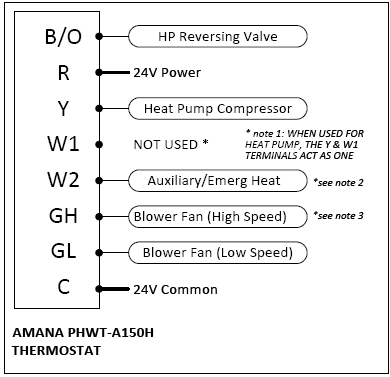
HEAT PUMP WIRING DIAGRAM NOTES
- Note 2: The “W2” terminal is used to call for Electric/ Auxiliary heat. If your Heat Pump PTAC does not have Electric heat, then the “W2” terminal should not be used and Installer Settings menu 10 (Aux. Stage Offset) should be set to “OFF”.
- Note 3: For PTAC units with only one fan speed (single “G” fan wire), add a jumper wire (installer provided) to bridge together “GH” and “GL”. Connect your fan wire to either terminal after jumper wire has been added.
For Heat Pump applications, the options below can be left per the factory defaults.
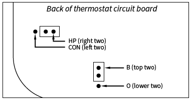
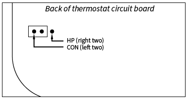
- HP/CON Option = “HP” position (default) is for heat pumps, and bridges Y and W1 terminals together. When set to “CON” the Y and W1 terminals operate independently for conventional systems.
- B/O Option = “B” setting (default) means the shared B/O terminal is energized while in Heat mode and off in Cool. “O” setting means the shared B/O terminal is energized while in Cool mode and off in Heat.
UP TO 1H/1C CONVENTIONAL APPLICATIONS
(AMANA PTC PTAC MODELS)
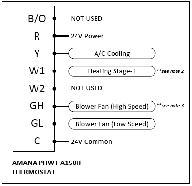
CONVENTIONAL WIRING DIAGRAM NOTES
- Note 1: For Conventional (cooling) PTAC units, Installer Settings menu 06 (System Type) must be set to “Con”.
- Note 2: If connecting to a Conventional PTAC unit without electric heat, the W1 and W2 wire terminals will not be used and Installer Settings menu 03 (Available Modes) should be set to “04: Cool Only”
- Note 3: For PTAC units with only one fan speed (single “G” fan wire), add a jumper wire (installer provided) to bridge together “GH” and “GL”. Connect your fan wire to either terminal after jumper wire has been added.
For Conventional (cooling) applications, the option below will need to be adjusted or confirmed during the install.
INSTALLER SETTINGS
| MENU# | SETTING | OPTIONS |
| 01 | Scale | F, C |
| 02 | Temp. Calibration | Zero, -5F to +5F (-3C to +3C) |
| — | ||
| 04 | Max. Heat | 60F to 90F (80F)
(16C to 32C) |
| 05 | Min. Cool | 60F to 80F (65F)
(7C to 24C) |
| 06 | System Type | HP=Heat Pump
Con=Conventional |
| — | ||
| 09 | Swing /
Temp. Differential |
±0.25F (±0.14C)
±0.50F (±0.28C) ±1.00F (±0.56C) ±2.25F (±1.25C) |
| 10 | Aux. Stage Offset
(for Heat Pumps only) |
Off
1: 1.0F (0.5C) 2: 2.0F (1.0C) 3: 3.0F (1.5C) 4: 4.0F (2.0C) 5: 5.0F (2.5C) |
| — | ||
| 17 | Backlight Always On | Off=Turn off 10 sec
On=Always On |
| 18 | Use default set temp. after mode change | ON: Uses default temps
OFF: Use last temp per mode |
| 19 | Default heat mode set temp. | 70F (21C)
60F to max heat set temp |
| 20 | Default cool mode set temp | 74F (23C)
60F to max set temp |
| — | ||
| 98 | Compressor Protection Bypass | No=Delays Remain
Yes=Suspend Delay |
| 99 | RESET | No=Save and Exit
Yes=Full Reset |
SETTING DESCRIPTIONS
- 01 (Scale): Displayed temperatures shown in F/C degrees.
- 02 (Temp. Calibration): Gives user flexibility to adjust the perceived measured temperature that is used for thermal control.
- 04 (Max. Heat): Sets the maximum temperature that a user can adjust the target temperature to for heating.
- 05 (Min. Cool): Sets the minimum temperature that a user can adjust the target temperature to for cooling.
- 06 (System Type): Selects the type of heating/cooling equipment that is present in the system.
- 09 (Swing / Temp. Differential): Determines how wide or narrow the temperature control band is between cut-in and cut-out.
- 10 (Aux.Stage Offset): Sets the number of degrees from the setpoint, that will cause the second heat stage to turn on.
- 17 (Backlight Always On): Allows the display backlight to remain on constantly, or turn off automatically after 10 seconds.
- 18 (Set Temp After Mode Change): Determines if the thermostat recalls the last used set temperature per mode, or uses a default set temperature when the mode is changed manually.
- 19 (Default Heat Mode Set Temp): Determines the default set temperature that is used when first selecting heat mode.
- 20 (Default Cool Mode Set Temp): Determines the default set temperature that is used when first selecting cool mode.
- 98 (Delay Bypass): Contractor/Installer mode, turns off the compressor delays for testing the system; returns automatically to normal operation after 10 minutes.
- 99 (RESET): Returns all settings back to factory defaults.
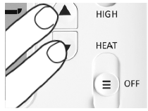
- With thermostat powered, move System Mode switch to the OFF position. Press and hold BOTH Up and Down buttons for at least 5 seconds, until the screen changes.
TO CHANGE AN ENTRY
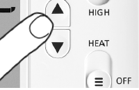
- Use the Up or Down buttons to change the setting option.
TO ADVANCE TO THE NEXT MENU ITEM
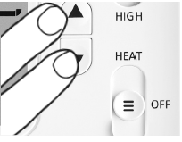
- Press BOTH the Up and Down buttons together.
TO RETURN TO THE MAIN THERMOSTAT SCREEN
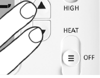
- Press BOTH the Up and Down buttons together after last menu item exits the settings menu.
Waiting for 1-Minute with no button presses will exit the settings menu with all items saved as they were last shown on the display screen.
Reference
Download Manual:
AMANA PHWT-A100C Non-Programmable Electronic Thermostat INSTALLATION INSTRUCTION

AMANA PHWT-A150H Non-Programmable Electronic Thermostat INSTALLATION INSTRUCTION