
WarmlyYours nSpire UDG4 Touch Programmable Thermostat
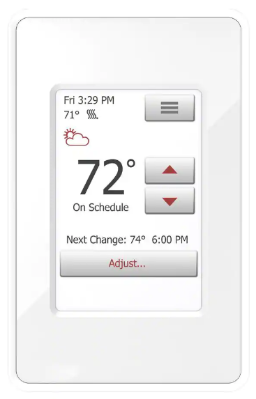
HOME SCREEN
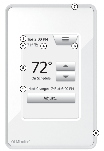
ITEMS
- Day and time
- Current temperature
- Target temperature or setpoint
- Heating indicator – when visible, the system is heating.
- Next scheduled change
- Access Main Menu
- GFCI/EGFPD Test Button
- On/Off/GFCI/EGFPD Reset Button
- Press to turn the system ON
- Hold to turn the system OFF
- Press to reset the GFCI/EGFPD
WARNINGS
To avoid electric shock, disconnect the heating system power supply at the main panel before installation and maintenance of the thermostat. Keep thermostat air vents clean and free from obstruction. This thermostat is an electrical device and must be installed in compliance with national and/or local electrical codes. Installation must be performed by qualified personnel where required by law. If a power module with an equipment ground fault protection device EGFPD) is to be installed where national and/or local electrical codes require a ground fault circuit interrupter (GFCI), a separate GFCI must also be installed.
CLASSIFICATION
The product is a Class II device (reinforced insulation) and must be connected to the following leads:
- Phase L1 (L) 120 V
- Neutral L2 (N) 0-120 V
- Max. load 15 A (resistive load)
- The thermostat is intended to be used with underfloor heating.
The heating element is in accordance with the supply voltage. The terminals are suitable for field wiring cables of 12 to 22 AWG.
TECHNICAL DATA
- Supply Range………………………………………………….. 120/240 Vac 50/60 Hz
- Load ……………………………………………………….max. 15 A (resistive load)
- Max. power at e.g. ………………………………………………..1800 W at 120 Vac
- ………………………………………………………………..3120 W at 208 Vac
- ………………………………………………………………..3600 W at 240 Vac
- a. UDG4 (GFCI)……………………………………………… Class A (5 mA trip level)
- b. ADG4 (EGFPD)…………………………………………………….. (15 mA trip level)
- Temperature range ………………………………… +5 to +40°C / +41 to +104°F
- Amb. temp. range …………………………………….. 0 to +25°C / +32 to +77°F
- Construction of Control………………………….Electronic room thermostat for
- regulating electrical underfloor heating.
- Method of Mounting Control…………………………….Independently mounted
- control for flush mounting
- Type of Action…………………………………………………………………… Type 2.B.
- Rated Impulse Voltage…………………………………………………………….2500 V
- Control Pollution Degree………………………………………………………………….2
CERTIFICATION
UL is Listed for the US and Canada According to the following standards: Thermostat: UL 60730-1
UL 60730-2-9
CSA E60730-1
CSA E60730-2-9
UL file number: E157297
a. UDG4 GFCI: UL 943 4th ed.
CSA C22.2 No. 144.1-06
b. ADG4 EGFPD UL 1053
CSA C22.2 No. 0.8
Scan the QR code for full user manual
For support please contact your installer or retailer.
OJ Electronics
Stenager 13B
DK-6400 Sønderborg
© 2016 OJ Electronics. All rights reserved.
This manual and parts thereof are protected under Danish and international copyright laws.
QUICK START GUIDE
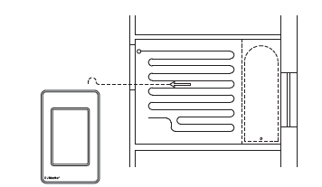
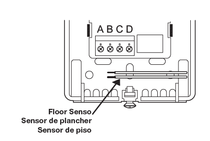
- The floor sensor is recommended placed in a nonconductive installation pipe, which is embedded in the floor. The pipe must be sealed in the end and placed as high as possible in the concrete layer. The sensor cable shall be placed in a separate pipe or be separated from power cables. The floor sensor must be centered in between the heating cable.
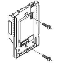
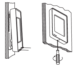
- Loosen the screw at the bottom and remove the faceplate.
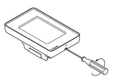
- Do not attempt to remove the screw completely.
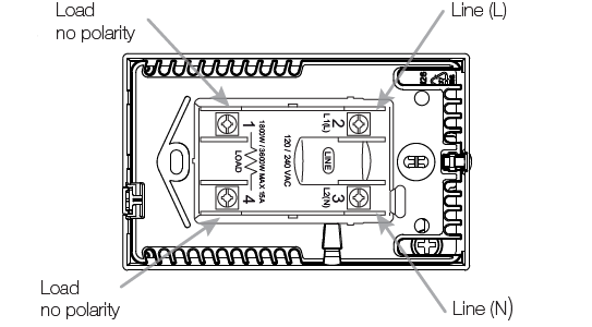
- Turn the power source OFF at the breaker panel. Make electrical connections to the power base. See Warnings. AWG between 12 and 20.
Note! Do not detach the screws from the terminals. When tightening the screws, use a torque of between 0.8 and 1.2 Nm. - The floor sensor must not come in contact with electrical wires in the wall and must be routed outside the electrical box.
- Push the power base into the electrical box. Secure the power base to the wall.
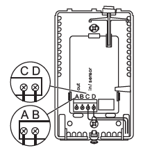
- The Floor sensor has no polarity. Connect it to terminals C and D. The power module connects to terminals A and B*Make the sensor connections.* Refer to the instructions included with the power module.
- Remount the faceplate. Tighten the screw at the bottom.
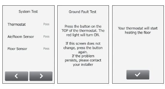
- Perform system and GFCI/EGFPD tests. Once the thermostat setup is complete, confirm “Your thermostat will start heating the floor” to complete the startup wizard.
REFERENCE:
Download Manual:
WarmlyYours nSpire UDG4 Touch Programmable Thermostat Quick Stat Guide
Other Manual:
WarmlyYours nSpire UDG4 Touch Programmable Thermostat with 2 Conduits Installation Guide
WarmlyYours nSpire UDG4 Touch Programmable Thermostat with single Conduits Installation Guide
WarmlyYours nSpire UDG4 Touch Programmable Thermostat with without Conduits Installation Guide
WarmlyYours nSpire UDG4 Touch Programmable Thermostat interactive User manual
![]()
WarmlyYours nSpire UDG4 Touch Programmable Thermostat Quick Start Guide
Leave a Reply