Vive Comfort TP-Z-955W Non-Programmable Thermostat
P.O. Box 3377
Springfield, MO 65804
Toll-Free: 1-800-776-1635
Web: www.vivecomfort.com
Hours of Operation: M-F 9AM – 6PM Eastern
| Description | |
| Gas or Oil Heat | Yes |
| Electric Furnace | Yes |
| Heat Pump (No Aux. or Emergency Heat) | Yes |
| Heat Pump (with Aux. or Emergency Heat) | Yes |
| Multi-stage Systems | Yes |
| Heat Only Systems | Yes |
| Cool Only Systems | Yes |
| Dual Fuel Systems | Yes |
| Millivolt | No |
This Package contains control equipment for MASTER ZONE ONLY. To add zones to this system, additional equipment is required. A total of 5 zones can be setup with this system.
Power Type
- Base Module: Hardwire
- TP-Z-DPMW: Hardwire
- TP-Z-955W: Hardwire (Common Wire) with Battery Backup
Additional zoning system equipment not included in this package.
- TP-Z-RISW: Zone Remote Thermostat (Battery Power)
- TP-Z-DPMW: Additional Damper Modules (Hardwire)
- TP-Z-ROSW: Outdoor Remote Sensor (Battery Power)
- TP-Z-RDASW: Discharge Air Sensor (Hardwire)
A trained, experienced technician must install this product.
Carefully read these instructions. You could damage this product or cause a hazardous condition if you fail to follow these instructions.
WIRELESS TYPE SELECTION
This Wireless Zoning System contains selectable wireless communication. Each component has a jumper switch labeled FSK and ASK. Default setting: FSK
- All components must be set to the same position for wireless communication.
- Both modes utilize a 916 MHz frequency.
- FSK: frequency-shift keying, this mode improves the signal transmission through dense materials.
- ASK: amplitude-shift keying, set all components to this mode in applications requiring use of the Wireless Repeater. All components are compatible with the Wireless Repeater in this mode.
(*The Wireless Repeater is an optional accessory to achieve exceptionally long wireless range. Most installations will not require the Wireless Repeater.)
NOTE: Anytime a jumper pin switch has been changed, the device needs to be reset or power cycled to configure the changed setting
ESTABLISHING COMMUNICATION
Establishing Communication between Master Thermostat and the Base Module
The thermostat and base module come factory linked out of the box. However, If communication is lost follow this easy- Two Step process to
re-establish the communication link.
- Press and hold the Base Module button for 3 seconds. The Blue LED will flash when ready to recieve initial signal from the Master Thermostat.
(Base Module must be powered by 24V. Blue LED will be continuously on when 24V power is present. - Hold the Light key (shown here) of the Master Thermostat for 10 seconds, the Blue LED on the base module will stop flashing after communication has been established between base module and the Master Thermostat.
Note: The Blue LED on the base module will be on when power is present. The Blue LED will flash 3 times every time it recieves a signal from Master Thermostat. When a relay is on the corresponding LED relay indicator will be on.
Note: If the base module does not recieve a signal from the Master Thermostat for 15 minutes it will turn off all relays until communication is reestablished. The Blue LED on the base module will also turn off to show communication has been lost.
Note: If communication has been lost for 1 hour and if freeze protection is enabled, heat and emergency heat relays will be turned on. The heat and emergency heat relays will turn on for 10 minutes every hour if there has been a call for heat in the last 24 hours.

Important: DO NOT hold the light button on the Master Thermostat for more than10 seconds after Step 2 above has been completed. Holding the light button down will break the communication link and the base module button will need to be pressed again to reestablish communication.
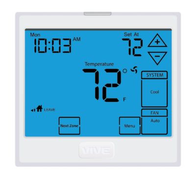
THERMOSTAT QUICK REFERENCE
Getting to know your thermostat
- LCD (right)
- Glow in the Dark Light Button
- Fan Button
- System Button
- Temperature Setpoint Buttons
- Menu Button
NOTE ABOUT THE LIGHT BUTTON:
This button is used to light up the display, but it is also used to set up communication with the base module.
DO NOT hold the light button down for more then 10 seconds, unless you are performing the initial communication setup steps.

Removing the private label badge
Gently slide a screwdriver into the bottom edge of the badge. Gently turn the screwdriver counter clockwise. The badge is held on by a magnet. The badge should pry off easily. Do not use force.
About the Badge
All our thermostats use the same universal magnetic badge.
Visit our website to learn more about our free private label program.
INSTALLATION TIPS
Wall locations
The thermostat should be installed approximately 4 to 5 feet above the floor.
Select an area with average temperature and good air circulation.
Do not install thermostat in locations:
- Close to hot or cold air ducts
- That are in direct sunlight
- With an outside wall behind the thermostat
- In areas that do not require conditioning
- Where there might be concealed chimneys or pipes
- Where appliances could radiate heat
- Where there are dead spots or drafts (in corners or behind doors)
Note: The Master Thermost MUST be hardwired (C and R terminals connected to 24 VAC). Batteries may be used for clock backup during power-outages.
Master Thermostat Subbase Installation:
Caution: Electrical Hazard
Failure to disconnect the power before beginning to install this product can cause electrical shock or equipment damage.
Mercury Notice:
All of our products are mercury free. However, if the product you are replacing contains mercury, dispose of it properly. Your local waste management authority can give you instructions on recycling and proper disposal.
For vertical mount put one screw top and one screw on bottom.
For horizontal mount put one screw left and one screw right.
NOTE:
To ensure a solid fit between the thermostat and the subbase, mount the subbase on a flat wall with the drywall anchors flush to the wall. Using the screws and drywall anchors that were provided with the thermostat.
Note: The Master Thermostat must be hardwired (C and R terminals connected to 24V power)
Equipment Base Module Installation Tips
Basement Installation
Wire Base Module with 8ft pigtail and temporarily mount. If you are not able to establish communication, this will allow you to relocate the Module to an area with less obstruction, without having to rewire.
Attic Installation
Locate a closet nearest the equipment. Then mount the base module high on the wall or on the ceiling inside the closet. This location will insure keeping below maximum temperature specification.
Wireless Range
The range between this module and the Master Thermostat is approximately 50ft in standard residential construction. To extend the range try placing the module higher, if in a basement try further away from large metal objects.

There is a channel for wiring on the back side of the module for surface mounting.
Installation Tip
Do not install the base module in locations:
- That are behind a chimney
- Where temperature could exceed 150ºF
- Where rain or snow or extreme hot or cold is possible
NOTE: The base module is NOT weatherproof.
Caution: Electrical Hazard
Failure to disconnect the power before beginning to install this product can cause electrical shock or equipment damage.
Base Module Subbase Installation
Wiring Note: Wire the base module subbase the same way you would wire a hardwired thermostat subbase.
Note: To connect the base module to master thermostat, refer to the directions on page 3 of this manual.
Note: The base module must be hardwired (C and R terminals connected to 24V power).
MOUNT THERMOSTAT & BATTERY INSTALLATION
Mount Thermostat and Base Module
Align the 4 tabs on the subbase with corresponding slots on the back of the thermostat or base module. Then push gently until the thermostat or base module snaps in place.
Note: To insure a solid fit between the thermostat and the subbase:
- Mount subbase to a flat wall
- Use screws provided
- Drywall anchors should be flush with the wall
- Wires should be pushed into the wall

Note: The base module can be wired from the back or the bottom.
Battery Installation

Battery Tip
The Master Thermostat must be hardwired (R and C terminals connected to 24 VAC). Batteries may be used for clock backup during power-outages, batteries are also recommended to simplify establishing communication process. This allows the installer to take the master thermostat to each zone they are connecting.
WIRING
Equipment Base Module Wiring
- If you are replacing a thermostat, make note of the terminal connections on the thermostat that is being replaced. In some cases the wiring connections will not be color coded. For example, the green wire may not be connected to the G terminal.
- Loosen the terminal block screws. Insert wires then retighten terminal block screws.
Warning: All components of the control system and the thermostat installation must conform to Class
II circuits per the NEC code.
Wire specifications
- Use shielded or non-shielded
- 18-22 gauge thermostat wire.
Note: In many heat pump systems with no emergency heat relay a jumper can be installed between E and W2.
Terminal Designations on Base Module
This thermostat is shipped from the factory to operate a conventional heating and cooling system. This thermostat will also operate a heat pump system. See the “heat pump” configuration step on page 14 of this manual to configure the thermostat for heat pump applications.
Terminal 2 Heat 2 Cool Conventional System 2 Heat 2 Cool Heat Pump System 3 Heat 2 Cool Heat Pump System
| RC | Transformer power (cooling) | Transformer power (cooling) | Transformer power (cooling) |
| RH | Transformer power (heating) | Transformer power (heating) | Transformer power (heating) |
| C | Transformer common | Transformer common | Transformer common |
| B | Energized in heating | Heat pump changeover valve energized in heating | Heat pump changeover valve energized in heating |
| O | Energized in cooling | Heat pump changeover valve energized in cooling | Heat pump changeover valve energized in cooling |
| G | Fan relay | Fan relay | Fan relay |
| W/E | First stage of heat | Emergency heat relay | Emergency heat relay |
| Y | First stage of cool | First stage of heat & cool | First stage of heat & cool |
| Y2 | Second stage of cool | Second stage of cool | Second stage of cool & second stage of heat |
| W2 | Second stage of heat | Auxiliary heat relay, second stage of heat | Auxiliary heat relay, third stage of heat |
Note: On most heat pump systems a jumper should be installed between W/E and W2.
Terminal Designations on Z955W Master Thermostat
| Terminal | 2 Heat 2 Cool Conventional System | 2 Heat 2 Cool Heat Pump System | 3 Heat 2 Cool Heat Pump System |
| R | 24 VAC Transformer power | 24 VAC Transformer power | 24 VAC Transformer power |
| C | Transformer common | Transformer common | Transformer common |
Equipment Base Module Wiring
- Power supply.
- Factory-installed jumper. Remove only when installing on 2-transformer systems.
- Use either O or B terminals for changeover valve.
Typical 2H/2C system: 1 transformer
Typical 3H/2C heat pump system
Typical heat-only system with fan
Typical 2H/2C system: 2 transformer

Typical heat-only system

Typical cool-only system
NOTE: In many heat pump systems with no emergency heat relay a jumper can be installed between E and W2.
This thermostat has a technician setup menu for easy installer configuration. To set up the thermostat for your particular application.
- Press MENU button
- Press and hold TECHNICIAN SETUP button for 3 seconds. This 3 second delay is designed so that homeowners do not accidentally access the installer settings.
- Configure the installer options as desired using the table below.
Use the keys to change settings and the NEXT STEP
or PREV STEP key to move from one step to another. Note: Only press DONE key when you want to exit the Technician Setup options.
Tech Setup Steps
Filter Change Reminder
This feature will flash FILT in the display after the elapsed run time to remind the user to change the filter. A setting of OFF will disable this feature.
Room Temperature Calibration
This feature allows the installer to change the calibration of the room temperature display. For example, if the thermostat reads 70° and you would like it to read 72° then select +2.
Minimum Compressor On Time
This feature allows the installer to select the minimum run time for the compressor.
For example, a setting of 4 will force the compressor to run for at least 4 minutes every time the compressor turns on, regardless of the room temperature.
Compressor Short Cycle Delay
The compressor short cycle delay protects the compressor from “short cycling”. This feature will not allow the compressor to be turned on for 5 minutes after it was last turned off.
Cooling Swing
The swing setting, often called “cycle rate”, “differential” or “anticipation” is adjustable. A smaller swing setting will cause more frequent cycles and a larger swing setting will cause fewer cycles.
Heating Swing
The swing setting, often called “cycle rate”, “differential” or “anticipation” is adjustable. A smaller swing setting will cause more frequent cycles and a larger swing setting will cause fewer cycles.
Keypad Lockout
Keypad lockout allows you to configure the thermostat so that none or some of the keys do not function.
LCD Will Show
Adjustment Options
- You can adjust the filter change reminder from OFF to 2000 hours of runtime in 50 hour increments.
- You can adjust the room temperature display to ready -4°F to +4°F above or below the factory calibrated reading.
- You can select the minimum compressor run time from “off”, “3”, “4”, or “5” minutes. If 3, 4, or 5 is selected, the compressor will run for at least the selected time before turning off.
- Selecting ON will not allow the compressor to be turned on for 5 minutes after the last time the compressor was on. Select OFF to remove this delay.
- The cooling swing setting is adjustable from ±0.2°F to
±2°F. For Example: A swing setting of 0.5°F will turn the cooling on at approximately 0.5°F above the setpoint and turn the cooling off at approximately 0.5°F below the setpoint. - The heating swing setting is adjustable from ±0.2°F to ±2°F. For Example: A swing setting of 0.5°F will turn the heating on at approximately 0.5°F below the setpoint and turn the heating off at approximately 0.5°F above the setpoint.
- Pick PA or FU
PA = partial keypad lockout, which locks all the keys except the keys.
keys.
FU = Full keypad lockout, which locks out all the keys.
Note: Keypad lockout instructions are below.
Factory Default Settings
- OFF
- 0 ºF
- OFF
- ON
- 0.5 ºF
- 0.4 ºF
- PA
Note: The function of activating your Keypad Lockout choice takes place after you have exited Tech Setup. If you do not perform this activation procedure, all keys will function freely. To lock the keypad hold down the![]() keys for 3 seconds.You will see a lock in thedisplay. To unlock the keypad hold down the
keys for 3 seconds.You will see a lock in thedisplay. To unlock the keypad hold down the ![]() keys for 3 seconds.
keys for 3 seconds.
| Heating Temperature Setpoint Limit | Cooling Temperature Setpoint Limit | ºF or ºC | 12 or 24 Hour Clock | Morning Recovery | Program Options | |
| This feature allows you to set a maximum heat setpoint value.
The setpoint temperature cannot be raised above this value. |
This feature allows you to set a minimum cool setpoint value.
The setpoint temperature cannot be lowered below this value. |
Select F for Fahrenheit temperature readout or select C for Celsius read out. | You can select either a 12 or 24-hour clock setting. | This feature turns your system on before the WAKE programming time to ensure the environment is at the WAKE setpoint when the WAKE time period begins. This recovery changes over time based on the previous day’s experience. | You can configure this thermostat to have a 7-day program, a 5+1+1 program, or a nonprogrammable one. | The display light can be configured to stay on at all times or come on when any key is pressed. |
LCD Will Show
Adjustment Options
- Use the key to select the maximum heat setpoint.
- Use the key to select the minimum cool setpoint.
- ºF for Fahrenheit
ºC for Celsius - Use the or key to select 12 or 24-hour clock.
- Use thekey to turn on or off.
- Use thekey to select 7d for 7 days, 5d for 5+1+1, or 0d for nonprogrammable.
- OFF configures the display light to come on when the light key or any button on the screen is pressed.
ON configures the display light to stay on.
Use thekey to turn on or off.
Factory Default Settings
- 90 ºF
- 44 ºF
- ºF
- 12 Hour Clock
- ON
- 5d
- OFF
Swing setting Tip
The second stage will turn on at 2x the swing setting. The second stage will turn off when 1x the swing is reached. For example, if the swing setting is .5 degrees for heating and the thermostat is set at 70ºF, the rst stage will turn on at approximately 69.5ºF. The second stage will turn on at 69.0ºF. The second stage will turn off at 69.5ºF and the first will turn off at 70.5ºF. If third stage is used, it will turn on at 3x the swing and turn off at approximately 2x the swing.
| Contractor Call Number | Beep | Heat Pump | Fan Operation | Gas Auxiliary for Heat Pump | Stages of Heat | Cooling Fan Delay |
| Allows you to put your phone number in the display.
You can choose ON or OFF |
When any key is pressed an audible beep will sound. You can choose
ON or OFF. |
When turned on the thermostat will operate a heat pump.
1. EM.Heat will show as an option in the system switch. 2. Y will be first stage of heat & cool, W/E will be emergency heat relay & W2 will be auxiliary heat relay. |
Select GAS for systems that control the fan during a call for heat.
Select ELEC to have the thermostat control the fan during a call for heat. |
This option will turn the heat pump off 45 seconds after the auxiliary heat relay turns on.
For 2 heat applications, the first stage will turn off 45 seconds after the auxiliary stage turns on. For 3 heat applications, the first and second stage will turn off 45 seconds after the auxiliary stage turns on. |
You can configure the thermostat to operate a 3 stage heat pump system.
2H 2C = 2 heat, 2 cool 3H 2C = 3 heat, 2 cool This feature only shows if Technician Setup Step for HEAT PUMP is set to ON. |
The cooling fan delay setting will delay the fan from coming on in cool mode and keep running after the compressor shuts off for a short time to save energy in some systems. |
LCD Will Show

Adjustment Options
- If selected ON, you will see the input screen after pressing the next step. Use the key to select the desired number and the key to move from one character to another. See note below on operation.
- If ON is selected the beep will sound. If OFF is selected there is no sound.
- OFF configures the thermostat for non-heat pump systems.
- ON configures the thermostat for heat pump systems.
- GAS or ELEC.
- For heat pump systems that are “dual fuel” (use a gas furnace for auxiliary stage heat) you can turn this feature on to turn off the heat pump when the auxiliary stage of heating has been called for. See Balance Point on page 15
- Use thekey to change between 2 heat and 3 heat. 2 heat will use Y1 as first stage and W2 as auxiliary. 3 heat will use Y1 as first stage, Y2 as second stage and W2 as auxiliary.
- You can select the Cooling Fan Delay from OFF, 15, 30, 60 or 90 seconds. If 15, 30, 60 or 90 is selected the fan will not turn on for that many seconds when there is a call for cool and will run for that many seconds after satisfying a call for cool.
Factory Default Settings
- OFF
- ON
- OFF
- GAS
- OFF
- 2 Stages
- OFF
Note: If contractor Call Number is selected ON, your phone number will show in the display if there has been a continuous call for heating or cooling for 24 hours or if the light button is held down for 3 seconds. To remove the phone number from the display, hold the light button down for 3 seconds.
| Outdoor Sensor | Zone Remote Thermostat | Freeze Protection | Zones Calling for 2nd Stage | Balance Point (Gas Auxiliary ON) | Balance Point (Gas Auxiliary OFF) | Balance Run Time |
| Enables the use of an outdoor sensor.
Connecting a sensor allows for Balance Point settings and will also display outdoor temperature. See the outdoor sensor user guide for more information. |
This step links a ZONE thermostat to a MASTER thermostat.
Master Thermostat is always Zone 1.
The ZONE thermostat controls zones 2-5 and 1 is required for each zone. |
Turns on the heat for 10 minutes each hour if unable to communicate with the
master thermostat, if there has been a call for heat in the last 24 hours. |
Configure the number of zones that must be calling for the same mode (heating or cooling) to allow 2nd stage to energize.
At least one of the zones must be calling for 2nd stage. For heat pump applications, the auxiliary heat will be allowed to energize if only one zone is calling for heating. If Balance Point is enabled, the Balance Point conditions must be met for auxiliary heat to energize. |
The balance point can eliminate the need for fosil fuel kit. An outdoor temperature above the balance point will cause the thermostat to only allow the Y terminal(s) to energize. An outdoor temperature below the balance point will cause the thermostat to only allow W2 to energize.
Note: Only shows up if Heat Pump is set to YES. Outdoor Sensor is turned ON, and GAS Auxiliary is turned ON. |
Balance point with electric auxiliary can optimize Heat Pump usage. An outdoor temperature above the balance point will cause the thermostat to only allow the Y terminal(s) to energize. An outdoor temperature below the balance point will cause the thermostat to allow the Y terminal(s) and the W2 terminal to energize.
Note: Only shows up if Heat Pump is set to YES and Outdoor Sensor is turned ON and GAS Auxiliary is turned OFF. |
Balance point run time will allow the W2 auxiliary terminal to energize even if the outdoor temperature is above the selected balance point temperature. If enabled, the auxiliary will energize for the current cycle after the balance point run time has expired. |
LCD Will Show

Adjustment Options
- When NO is selected the thermostat is unable to connect to an outdoor remote sensor. When YES is selected the thermostat is able to connect to an outdoor remote sensor.Press and hold connect button on sensor until the Master Thermostat says FOUND OUTDOOR on display.
- The number shown represents the zone, 2-5. Use to select the zone you wish to connect.
The zone setting on the Master Thermostat and the Zone thermostat must be the same to connect. See the zone thermostat Installation Manual for detailed connection information. - YES enables freeze protection NO disables freeze protection.
- Useto select 1, 2, or 3 zones that must be calling to allow 2nd stage to energize.
The number of zones calling for the same mode, with at least one zone calling for 2nd stage, must match this setting to allow 2nd stage to energize. - 10, 20,30, 35, 40, 45, 50 outdoor temperature balance point setting. NO
- 10, 20,30, 35, 40, 45, 50 outdoor temperature balance point setting. NO
- YES 15, 30, 45, 60, 75, 90 continuous run time minutes. NO
Factory Default Settings
- NO
- 2
- NO
- 1
- NO
- NO
- NO
Note: Connect an optional outdoor remote temperature sensor to enable the balance point tech setup option.
Note: Static/ Barometirc Bypass damper is recommended on all systems for safe and efficient zoning.
| Tech Setup Steps (Continued) | Requires ZDA250W | End of Tech Setup | |||
| Link Damper Module | Damper Default Position | Discharge Air Sensor | Discharge Air Sensor High-Temperature Limit | Discharge Air Sensor LOW-Temperature Limit | Satisfy Setpoint |
| This step connects the Z955W to Damper Modules.
Each Damper Module will open and close the damper(s) for the zone that is configured to control. This will indicate the zone number is it configured for using the Zone 1-5 LED indicators. |
Configure the desired damper position when all zones are satisfied.
All damper modules will control the damper to this position when calls for heating, cooling, and fan are complete. The module indicates the damper position using Zone 1-5 LEDs. When the damper is closed, the Zone LED will be on solid. When the damper is open, the Zone LED will be flashing. |
This step connects a DAS to the Z955W.
Connecting a DAS allows for high and low discharge air temperature limit settings. The discharge air temperature sensor is recommended for safe and efficient zoning. |
Configure the discharge (supply) air high temperature limit to prevent overheating.
When the discharge air temperature exceeds this setting, heating will de-energize and the fan will remain energized to distribute the warmed air to the zone(s) calling for heat. Heating will energize when the discharge air temperature drops below the limit and the zone(s) still call for heat. |
Configure the discharge (supply) air low-temperature limit to prevent coil freezing. When the discharge air temperature is below this setting, cooling will
de-energize and the fan will remain energized to distribute the cooled air to the zone(s) calling for cool. Coding will re-energize when the temperature is above the limit if zone(s) is still calling. |
This feature allows the thermostat to keep multiple stages of heat or cool energized until the setpoint is satisfied. |
LCD Will Show
Adjustment Options
- Use – and+ to select the zone number, Zone 1-5. The damper modules for the selected zone must be in Learn Mode. Hold the modules Learn Button until the communication LED begins flashing steady. Press and hold the FAN key on Z955W to link and configure the Damper Module for the zone number shown. Select the next zone number and repeat.
- Use – and + to select NO or NC.
When NO is selected, the damper position will default-open when all zones are satisfied. When NC is selected, the damper position will default-close when all zones are satisfied. - When NO is selected, the thermostat is unable to connect to a discharge air sensor.
When YES is selected, the thermostat is able to connect to a discharge air sensor.
Press and hold the connect button on the sensor until the Z955W shows FOUND DAS on the display. - Use the – and + to select the discharge air high temperature limit. Options are:
110, 120, 130, 140, 150, 160 degrees F. - Use – and + to select the discharge air low-temperature limit Options are 40-50 degrees F.
- Use the or key to turn on off.
Factory Default Settings
- 1
- NO
- NO
- 130°F
- 43°F
- OFF
PROGRAMMING THE THERMOSTAT
Set Time
Follow the steps below to set the day of the week and current time:
- Press MENU
- Press SET TIME
- Day of the week will be flashing. Use thekey to select the current day of the week.
- Press NEXT STEP
- The current hour is flashing. Use the key to select the current hour. When using 12-hour time, make sure the correct a.m. or p.m. choice is selected.
- Press NEXT STEP
- Minutes are now flashing. Use the key to select current minutes.
- Press DONE when completed.
Programming
All programmable thermostats are shipped with an energy saving pre-program. You can customize
this default program by following the Set Program Schedule.
Your thermostat can be programmed to have each day of the week programmed uniquely (7days), all the weekdays the same with a separate program for Saturday and a separate program for Sunday (5+1+1), or nonprogrammable. There are four time periods for each day ( WAKE, LEAVE, RETURN , SLEEP ). This thermostat has a programmable fan feature, which allows you to run the fan continuously during any time period. Programmable fan is available for Local Zone 1.
Factory Default Program
| Day of the Week | Events | Time | Setpoint Temperature (Heat) | Setpoint Temperature (Cool) |
| Weekday | Wake | 6 a.m. | 70° F (21° C) | 75° F (24° C) |
| Leave | 8 a.m. | 62° F (17° C) | 83° F (28° C) | |
| Return | 6 p.m. | 70° F (21° C) | 75° F (24° C) | |
| Sleep | 10 p.m. | 62° F (17° C) | 78° F (26° C) | |
| Saturday | Wake | 8 a.m. | 70° F (21° C) | 75° F (24° C) |
| Leave | 10 a.m. | 62° F (17° C) | 83° F (28° C) | |
| Return | 6 p.m. | 70° F (21° C) | 75° F (24° C) | |
| Sleep | 11 p.m. | 62° F (17° C) | 78° F (26° C) | |
| Sunday | Wake | 8 a.m. | 70° F (21° C) | 75° F (24° C) |
| Leave | 10 a.m. | 62° F (17° C) | 83° F (28° C) | |
| Return | 6 p.m. | 70° F (21° C) | 75° F (24° C) | |
| Sleep | 11 p.m. | 62° F (17° C) | 78° F (26° C) | |
You can use the table below to plan your customized program schedule if using 5+1+1.
| Day of the Week | Events | Time | Setpoint Temperature (Heat) | Setpoint Temperature (Cool) |
| Weekday | Wake | |||
| Leave | ||||
| Return | ||||
| Sleep | ||||
| Saturday | Wake | |||
| Leave | ||||
| Return | ||||
| Sleep | ||||
| Sunday | Wake | |||
| Leave | ||||
| Return | ||||
| Sleep | ||||
Note: The scheduled programming for ALL zones is done by and kept in the memory of the Z955W Mater Thermostat. Although CONTROL of an independent zone can be given to that zone’s thermostat, its programming is done by the Master Thermostat.
Set 5+1+1 Program Schedule
To customize your 5+1+1 program schedule, follow these steps Weekday:
- Select HEAT or COOL using the SYSTEM key.
Note: You have to program heat and cool each separately. - Press MENU
- Press SET SCHED . Note: Monday-Friday is displayed and the WAKE icon is shown. You are now programming the WAKE time period for the weekday setting.
Additional Step for Independent Zone Programming
The NEXT ZONE key can be pressed to select each zone to be programmed. The system information will display the name of the zone that is being programmed. Each zone can be programmed independently. - The first zone to be programmed will be named LOCAL. Use thekey to make your time selection for the weekday WAKE time period. Note: If you want the fan to run continuously during this time period, select ON with the FAN key. This can only be done for your LOCAL ZONE 1.
- Use the key to make your setpoint selection for the weekday WAKE period.
- Press NEXT ZONE. Repeat steps 4 and 5 for each remaining zone. Press NEXT ZONE to toggle zones. NOTE: Zones can have names such as LIVING ROOM, BEDROOM, etc.
- Press NEXT STEP
- Repeat steps 4 through 7 for weekday LEAVE time period, for weekday RETURN time period, and for the weekday SLEEP time period.
Saturday: - Repeat steps 4 through 7 for Saturday WAKE time period, for Saturday LEAVE time period, for Saturday RETURN time period, and for Saturday SLEEP time period.
Sunday: - Repeat steps 4 through 7 for Sunday WAKE time period, for Sunday LEAVE time period, for Sunday RETURN time period, and for Sunday SLEEP time period.
Set 7 Day Program Schedule
To customize your 7 day program schedule, follow these steps:
Monday
- Select HEAT or COOL using the SYSTEM key.
Note: You have to program heat and cool each separately. - Press MENU
- Press SET SCHED. Note: Monday-Friday is displayed and the WAKE icon is shown. You are now programming the WAKE time period for the weekday setting.
Additional Step for Independent Zone Programming
The NEXT ZONE key can be pressed to select each zone to be programmed. The system information will display the name of the zone that is being programmed. Each zone can be programmed independently. - The first zone to be programmed will be named LOCAL. Use thekey to make your time selection for the weekday WAKE time period. Note: If you want the fan to run continuously during this time period, select ON with the FAN key. This can only be done for your local zone 1.
- Use the key to make your setpoint selection for the weekday WAKE period.
- Press NEXT ZONE. Repeat steps 4 and 5 for each remaining zone. Press NEXT ZONE to toggle zones. NOTE: Zones can have names such as LIVING ROOM, BEDROOM, etc.
- Press NEXT STEP
- Repeat steps 4 through 7 for the weekday LEAVE time period, for the weekday RETURN time period, and for the weekday SLEEP time period.
Repeat steps 4 thru 7 for the remaining days of the week.
Repeat steps 4 thru 7 for the remaining days of the week.
A Note About Zone Control:
The Master Thermostat operates as Zone 1 of the Zoning System. Additional zones are controlled by zone thermostats. Use the Next Zone key to view the status of additional zones. The Zone Name, Ambient Temperature, System Mode & Setpoint are displayed. Control of additional zones can be given to the zone thermostat or the Master Thermostat.
A Note About Programmable Fan:
The programmable fan feature will run the fan continuously during any time period it is programmed to be on. This is the best way to keep the air circulated and eliminate hot and cold spots in your building. The programmable fan is available for Zone 1, the Local (Master) Zone.
Specifications
- The display range of temperature: 41ºF to 95ºF (5ºC to 35ºC)
- The control range of temperature: 44ºF to 90ºF (7ºC to 32ºC)
- Load rating: 1 amp per terminal, 1.5 amp maximum for all terminals combined
- Display accuracy: ± 1ºF
- Swing (cycle rate or differential)
- The heating is adjustable from 0.2ºF to 2.0ºF
- Cooling is adjustable from 0.2ºF to 2.0ºF
- Power source: 18 to 30 VAC, NEC Class II, 50/60 Hz for hardwire (common wire)
- Operating ambient: 32ºF to +105ºF (0º to +41ºC)
- Operating humidity: 90% non-condensing maximum
- Dimensions of thermostat: 4.7”W x 4.4 ”H x 1.1”D
- Frequency: 916 MHz
Base Module
- Load rating: 1 amp per terminal, 1.5 amp maximum for all terminals combined
- Power source: 18 to 30 VAC, NEC Class II, 50/60 Hz
- Operating ambient: 32ºF to +105ºF (0º to +65ºC)
- Operating humidity: 90% non-condensing maximum
Reference
Download Manual:
Vive Comfort TP-Z-955W Non-Programmable Thermostat Installation Manual
OTHER MANUALS
Vive Comfort TP-Z-955W Non-Programmable Thermostat Operational Manual
Vive Comfort TP-Z-955W Non-Programmable Thermostat Installation Manual