Vive Comfort TP-N-731W(O) Non-Programmable Thermostat
Wall Locations
The thermostat should be installed approximately 4 to 5 feet above the floor. Select an area with average temperature and good air circulation.
Do not install thermostat in locations:
- Close to hot or cold air ducts
- That are in direct sunlight
- With an outside wall behind the thermostat
- In areas that do not require conditioning
- Where there are dead spots or drafts (in corners or behind doors)
- Where there might be concealed chimneys or pipes

Thermostat Application Guide
| Description | |
| Gas or Oil Heat | Yes |
| Electric Furnace | Yes |
| Heat Pump (No Aux. or Emergency Heat) | Yes |
| Heat Pump (With Aux. or Emergency Heat) | Yes |
| Multi-Stage Systems | Yes |
| Heat Only Systems | Yes |
| Cool Only Systems | Yes |
| Millivolt | Yes |
Power Type
- Battery Power
- Hardwire (Common Wire)
- Hardwire (Common Wire) with
- Battery Backup
Subbase Installation
- Horizontal Mount
- Vertical Mount

Mount Thermostat
Align the 4 tabs on the subbase with corresponding slots on the back of the thermostat, then push gently until the thermostat snaps in place.
Battery Installation
Battery installation is recommended even if the thermostat is hardwired (C terminal connected). When the thermostat is hardwired and batteries are installed, the thermostat will activate a compressor delay of 5 minutes when it detects a power outage from the hardwired power supply.
Important:
High quality alkaline batteries are recommended. Rechargeable batteries or low quality batteries do not guarantee a 1-year life span
Getting to know your thermostat
- LCD
- Glow in the Dark Light Button
- Setpoint Buttons
- Fan Button
- System Button
- Occupancy Sensor
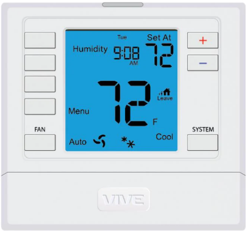
Thermostat Quick Reference
- Ambient Temperature: Displays the current room temperature
- Set At Temperature: Displays the selected desired room temperature
- Staging Indicators: If these or the fan indicators are flashing, it means that the system is in a delay of some type (compressor delay, cooling fan delay, or staging delay) or a pending change.
- Energy Efficient Globe: Indicates you are making an energy efficient set at temperature.
- Wireless Symbol: Indicates you have a wireless connection
- Low Battery Indicator: Replace batteries when this indicator appears.
Base Module Mounting Tips
Range between the thermostat and the base module is up to 100 feet with no obstructions and up to 50 feet through standard building materials. To optimize the range try placing the base module with no metal between it and the thermostat. The base module is designed to be mounted behind the front grille of a packaged terminal air conditioner (PTAC). Refer to the PTAC manufacturer’s manual for instruction to remove the front grille. Check clearance to ensure the fit of front grille after base module installation. See below for a few location recommendations
When Working With A Vertical Unit
- Do not mount Module inside the cabinet of the unit, or in a metal enclosure.
- Mount on the outside of the unit to maximize wireless communication

When Working With A Metal Sleeve Cabinet, Room Cabinet, or PTAC Cover
- If cabinet has open bottom, mount the module just inside the cabinet as close to the open bottom as possible without placing it in danger of being bumped or touched by furnishings, vaccum, etc.
- Another good module location would be on the underside of the top of the cabinet or cover. Directly behind the open Louver/Grill.

Wiring
- If you are replacing a thermostat, make note of the terminal connections on the thermostat that is being replaced.
- In some cases the wiring connections will not be color coded. For example, the green wire may not be connected to the G terminal.
- Loosen the terminal block screws.
- Insert wires then retighten the terminal block screws.
- Place nonflammable insulation into the wall opening to prevent drafts

Thermostat Wiring Tips
C Terminal
The C (common wire) terminal does not have to be connected when the thermostat is powered by batteries
Wire Specifications
Use shielded or non-shielded 18-22 gauge thermostat wire.
Terminal Designations
|
Terminal |
2 Heat 2 Cool Conventional System | 2 Heat 2 Cool Heat Pump System | 3 Heat 2 Cool Heat Pump System |
| RC | Transformer power (cooling) | Transformer power (cooling) | Transformer power (cooling) |
| RH | Transformer power (heating) | Transformer power (heating) | Transformer power (heating) |
| C | Transformer common | Transformer common | Transformer common |
| B | Energized in heating | Heat pump changeover valve energized in heating | Heat pump changeover valve energized in heating |
| O | Energized in cooling | Heat pump changeover valve energized in cooling | Heat pump changeover valve energized in cooling |
| G | Fan relay | Fan relay | Fan relay |
| W/E | The first stage of heat | The first stage of emergency heat | The first stage of emergency heat |
| Y | The first stage of cool | The first stage of heat & cool | The first stage of heat & cool |
| Y2 | The second stage of cool | The second stage of cool | The second stage of cool & second stage of heat |
| W2 | The second stage of heat | Auxiliary heat relay, the second stage of heat | Auxiliary heat relay, the third stage of heat |
Wiring Diagrams


Technician Setup Menu
- To enter Tech Setup Menu, press and hold
 together for 3 seconds.
 - Use to select the desired valve for each setting.
- Tap previous or next to select different tech settings.
- To exit Tech Setup Menu, press and hold together for 3 seconds or wait 60 seconds


Establishing A Connection
Establishing Communication between the thermostat & the base module
The thermostat and base module in this package are linked at our factory. Upon powering up, they will automatically begin communicating. If you wish to make any changes to the network such as adding or removing devices, please follow the instructions on this page.
How To Pair
On the Base module:
- Press the button next to the LED once.
- The Base module will begin double blinking pink for 2 minutes while it waits for a remote to join.
- Once a device joins, the LED will show green blinks and return to normal operating mode.
- To add another device, repeat the process.
On the Thermostat:
- Press hold the light button for 3 seconds. The LED will flash 3 times and pair with the base module.
- The thermostat will attempt to connect to a base module within the range
- Once paired, the LCD will temporarily display “PAIRED” when it joins with a base module.
How To Unpair
On the Base Module:
- PRESS HOLD the button next to the LED for 6 seconds.
- The Base module LED will turn RED for 6 seconds.
- All connected devices will be deleted.
On the Thermostat:
- Enter the “UNPAIRING” tech menu.
- Press hold the “+” button.
- The LCD will show “UNPAIRED”.
- The Thermostat will no longer be connected to a network.
Base Module LED Information
- The base module’s LED is used to communicate the status of the wireless network.
- Green Blink at 3s: Normal operating mode. All devices are connected and healthy.
- Yellow Blink at 3s: Normal operating mode. One or more (but not all) remote devices are NOT reporting.
- Red Blink at 3s: Normal operating mode. ALL network devices are NOT reporting.
- White Blink at 3s: Unpaired mode. Base module is powered but is NOT paired to any remotes.
- Blue double blink: Transmission received from a remote.
- Purple double blink: Base module is in pairing mode waiting for a remote.
- Green 5 quick blinks: A remote has successfully been added to the base modules network.
Network Specifications
Wireless Network Specifications
- The thermostat will attempt to pair with the first base module it “hears”. Do not attempt to create more than one “pair” at the same time in the same place.
- To ensure paring success, place the T731W(O) within a few feet of the base module while pairing. Once paired, the signal strength tech menu can be used to ensure a robust wireless connection.
- Placing either device in or around large metal objects can severely degrade the wireless range.
- The wireless network will automatically recover in the event of a power loss or temporary signal loss
Network Capabilities
- A single base module can support a single thermostat.
- The thermostat will require up to 60 seconds to reflect changes.
Specifications
Thermostat
- The display range of temperature … 41˚F to 95˚F (5˚C to 35˚C)
- The control range of temperature…. 44˚F to 90˚F (7˚C to 32˚C)
- Load rating………………………………………….1 amp per terminal, 1.5 amp maximum all terminals combined
- Swing (cycle rate or differential) …… Heating is adjustable from 0.2˚ to 2.0˚
- Cooling is adjustable from 0.2˚ to 2.0˚
- Power source …………………………………….18 to 30 VAC, NEC Class II, 50/60 Hz for hardwire
- Battery power from 2 AA Alkaline batteries
- Operating ambient …………………………. 32˚F to +105˚F (0˚C to +41˚C)
- Operating humidity ………………………… 90% non-condensing maximum
- Dimensions of thermostat …………….. 4.7”W x 4.4”H x 1.1”D
- Frequency ………………………………………… 916 MHz
Base Module
- Load rating ……………………………………….. 1 amp per terminal, 1.5 amp maximum for all terminals combined.
- Power source …………………………………….18 to 30 VAC, NEC Class II, 50/60 Hz
- Operating ambient …………………………. 32˚F to +150˚F (0˚C to +65˚C)
- Operating humidity ………………………… 90% non-condensing maximum
Reference
Download Manual:
Vive Comfort TP-N-731W(O) Non-Programmable Thermostat Installation Manual
OTHER MANUALS
Vive Comfort TP-N-731W(O) Non-Programmable Thermostat Operational Manual
![]()
Vive Comfort TP-N-731W(O) Non-Programmable Thermostat Installation Manual