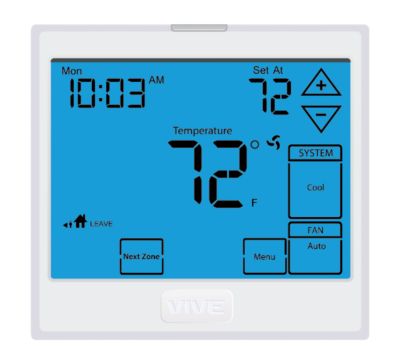
Vive Comfort TP-N-601 Non-Programmable Thermostat
Wall Locations
The thermostat should be installed approximately 4 to 5 feet above the floor. Select an area with average temperature and good air circulation
Do not install thermostat in locations:
- Close to hot or cold air ducts
- That are in direct sunlight
- With an outside wall behind the thermostat
- In areas that do not require conditioning
- Where there are dead spots or drafts (in corners or behind doors)
- Where there might be concealed chimneys or pipes
Thermostat Application Guide
| Description | |
| Gas or Oil Heat | Yes |
| Electric Furnace | Yes |
| Heat Pump (No Aux. or Emergency Heat) | Yes |
| Heat Pump (With Aux. or Emergency Heat) | Yes |
| Multi-Stage Systems | Yes |
| Heat Only Systems | Yes |
| Cool Only Systems | Yes |
| Millivolt | Yes |
Power Type
- Battery Power
- Hardwire (Common Wire)
- Hardwire (Common Wire) with
- Battery Backup
Subbase Installation
- Horizontal Mount
- Vertical Mount

Mount Thermostat
Align the 4 tabs on the subbase with corresponding slots on the back of the thermostat, then push gently until the thermostat snaps in place
Battery Installation
Battery installation is recommended even if the thermostat is hardwired (C terminal connected). When the thermostat is hardwired and batteries are installed, the thermostat will activate a compressor delay of 5 minutes when it detects a power outage from the hardwired power supply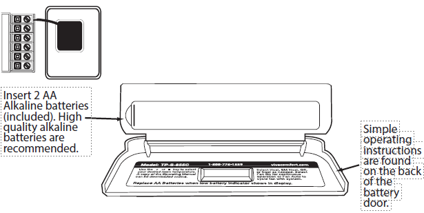
Gas or Electric Setup
Gas: For systems that control the fan during a call for heat, put the fan operation switch to the GAS position.
Electric: For systems that do not control the fan during a call for heat, put the fan operation switch to the ELECTRIC position.
Getting to know your thermostat
- LCD
- Temperature setpoint buttons
- Fan switch
- System switch
- Easy change battery door

Removing The Private Label Badge
All of our thermostats use the same universal magnetic badge. Visit the company website to learn more about our free private label program
About The Badge
All of our thermostats use the same universal magnetic badge. Visit the company website to learn more about our free private label program
Wiring
- If you are replacing a thermostat, make note of the terminal connections on the thermostat that is being replaced.
- In some cases the wiring connections will not be color coded. For example, the green wire may not be connected to the G terminal.
- Loosen the terminal block screws.
- Insert wires then retighten the terminal block screws.
- Place non-flammable insulation into the wall opening to prevent drafts.
Terminal Designations
- C Common wire from secondary side of cooling system transformer
- O Heat pump changeover valve energized in cooling
- B Heat pump changeover valve energized in heating
- W Heat relay
- RH Transformer power for heating
- RC Transformer power for cooling
- G Fan relay
- Y Compressor relay
RH & RC Terminals
For single transformer systems, leave the jumper wire in place between RH and RC. Remove jumper wire for two transformer systems.
Heat Pump Systems
If wiring to a heat pump, use a small piece of wire (not supplied) to connect terminals W and Y.
C Terminal
The C (common wire) terminal does not have to be connected when the thermostat is powered by batteries.
Wire Specifications
Use shielded or non-shielded 18-22 gauge thermostat wire.
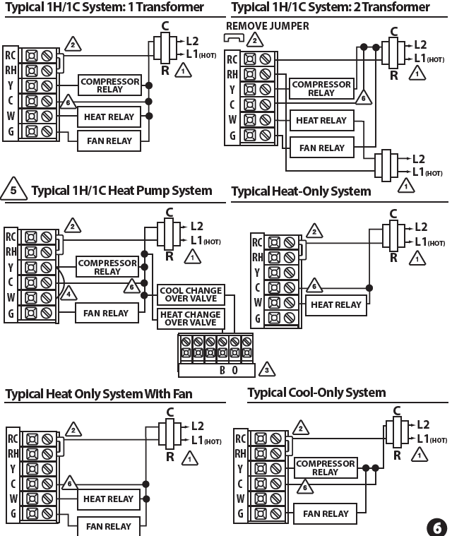
Wiring Diagrams
- Power supply
- Factory-installed jumper. Remove only when installing on 2-transformer systems Use either O or B terminals for changeover valve
- Use a small piece of wire (not supplied) to connect W and Y terminals
- Set fan operation switch to Electric
- Optional 24 VAC common connection when thermostat is used in battery power mode
Technician Setup
- Select OFF with the System Switch.
- Press and hold the + and – buttons together for 3 seconds.
- Use the + and – to change setting for that step, press the + and -simultaneously to change between tech settings.
- To exit Tech Settings, slide the System Switch to a different position or wait approximately 20 seconds.

Reference
Download Manual:
Vive Comfort TP-N-601 Non-Programmable Thermostat Installation Manual
OTHER MANUALS
Vive Comfort TP-N-601 Non-Programmable Thermostat Operational Manual

Vive Comfort TP-N-601 Non-Programmable Thermostat Installation Manual