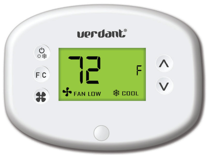
Verdant VXDB-TW-KT-W Wireless Thermostat
Introduction
Verdant VX Series Energy Management Thermostats deliver unprecedented energy savings without compromising the comfort of occupants.
An Integrated occupancy sensor uses a combination of motion and thermal sensing technologies for accurate occupancy detection. Reliable occupancy detection allows for energy savings when rooms are unoccupied.
Energy-saving presets eliminate the guesswork and make it easy to adjust the energy-saving settings.
Fully configurable energy-saving settings allow for customization of the thermostat energy-saving settings to fit any situation.
Comprehensive configuration options ensure full compatibility with virtually any existing or emerging HVAC system with up to 2 heat and 1 cool stages. Built-in wireless mesh networking enables online management.
NOTICE
TO ENABLE THE NETWORKING CAPABILITIES OF THE VX THERMOSTAT, REFER
TO THE “NETWORK INSTALLATION” SECTION OF THIS MANUAL.
BEFORE STARTING THE INSTALLATION OF THE NETWORKED THERMOSTATS, ENSURE THAT THE ONLINE CONNECTION KIT IS CONNECTED TO THE INTERNET.
THE ONLINE CONNECTION KIT MUST BE PLUGGED INTO AN INTERNET PORT WITH A PRIVATE IP ADDRESS WITH DHCP ACTIVE. THE ONLINE THE CONNECTION KIT MUST BE WHITELISTED USING ITS MAC ADDRESS WITH UNRESTRICTED INTERNET ACCESS. PORTS 80,443, AND 22 MUST BE OPEN TO INBOUND/OUTBOUND COMMUNICATION.
PLEASE CONFIRM WITH A VERDANT TECHNICAL SUPPORT AGENT THAT THE ONLINE CONNECTION KIT IS COMMUNICATING PROPERLY WITH THE CLOUD SERVICE BY CALLING OUR TECHNICAL SUPPORT TEAM AT 1 877 318 1823.
Network Installation
Connecting the Antenna Module
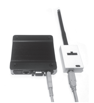
- Screw the Antenna onto the Wireless Receiver;
- Connect the Wireless Receiver to the Server using the supplied USB cable;
- Affix the Wireless Receiver to the wall with double-sided adhesive tape;
- Orient the antenna to be parallel to the closest room in which a Verdant thermostat will be installed.
THE WIRELESS RECEIVER AND THE ANTENNA MUST NOT BE INSTALLED NEAR METAL STRUCTURES OR SURFACES.
METAL STRUCTURES AND SURFACES SIGNIFICANTLY REDUCE THE RANGE OF THE WIRELESS SIGNAL.
Online Connection Kit Installation
Connecting the Ethernet Cable
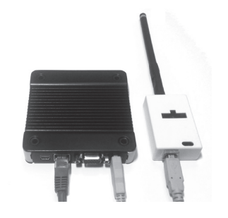 Connect the Server to the LAN port with the supplied RJ-45 cable.
Powering on the Server
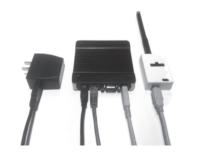
Plug the Server into an electrical outlet with the supplied power cord.
TO PREVENT POWER-RELATED ISSUES, PLUG THE SERVER INTO A UPS (UNINTERRUPTED POWER SUPPLY) UNIT.
Configuring the Online Connection Kit
- Ensure the Online Connection Kit is receiving a Private or Static IP address via DHCP Server. A public IP will not work;
- Ensure that the MAC address is properly Whitelisted if it needs to bypass a login (splash) page to be able to reach the internet. The MAC address is printed on a white sticker on the bottom of the Online Connection Kit.
- If behind a firewall, ports 22,80, and 443 must be open for the Online Connection Kit.
HVAC Controller Installation
Installing the HVAC Controller in an HVAC Unit
- Power Off the HVAC unit;
- Connect the HVAC Controller to the thermostat terminals on the HVAC unit – refer to the Wiring Table to determine proper connections.
THE HVAC CONTROLLER ANTENNA MUST BE FACING THE THERMOSTAT AND MUST NOT BE TOUCHED OR ENCLOSED BY ANY METAL COMPONENTS IN THE HVAC UNIT.
THE HVAC CONTROLLER MUST BE MOUNTED SO IT CANNOT FALL INTO THE HVAC UNIT CONDENSATION PAN. WE RECOMMEND USING PLASTIC CABLE TIES, OR 3M COMMAND TAPE (NOT SUPPLIED).
| Terminal Letter | Terminal Connection | AC Only | AC + HEAT | HP Only | HP + HEAT |
| W | Heat | X | ✔ | X | ✔ |
| Y | Compressor | ✔ | ✔ | ✔ | ✔ |
| O/B | Reverse Valve | X | X | ✔ | ✔ |
| C | Common | ✔ | ✔ | ✔ | ✔ |
| R | 24V | ✔ | ✔ | ✔ | ✔ |
| GL | Fan Low | ✔ | ✔ | ✔ | ✔ |
| GH | Fan High | ✔ | ✔ | ✔ | ✔ |
| Aux | Aux | Optional | |||
NOTE: If the HVAC unit has only one (1) fan speed, connect both fan control wires – Green and Purple – to the fan terminal (G).
For Installation on PTAC Units;
- Mount the HVAC Controller inside of the HVAC unit.
- Set the unit to “External Thermostat” (Class 2) mode. Consult the HVAC unit documentation to determine how to set the PTAC unit to “External Thermostat” mode.
For other units;
- Consult the HVAC manufacturer’s documentation or use a voltmeter to determine the voltage output (24V).
For Fan Coils;
- Ensure the HVAC controller is installed outside of the fan coil’s metal enclosure. The HVAC controller will not communicate properly inside of any metal enclosure.
- Ensure to adhere to all applicable electrical codes.
IF THE HVAC UNIT VOLTAGE OUTPUT IS MORE THAN 30VAC, YOU WILL REQUIRE A HIGH-VOLTAGE HVAC CONTROLLER (VX-HV-CC).*
PLEASE VERIFY THAT YOU HAVE THE CORRECT PARTS BEFORE BEGINNING INSTALLATION. IF YOU DO NOT HAVE THE CORRECT PARTS, CEASE INSTALLATION IMMEDIATELY AND CALL VERDANT TECHNICAL SUPPORT AT 1 877 318 1823.
Thermostat Installation
Mounting the Thermostat to the Wall
- Select the appropriate installation location for the thermostat, taking into account the following;
THE THERMOSTAT’S OCCUPANCY SENSOR SHOULD FACE THE BED AREA OF THE ROOM OR THE AREA WHERE THE OCCUPANT WILL SPEND THE MOST TIME.
THE THERMOSTAT MUST NOT BE INSTALLED IN THE VICINITY OF METAL STRUCTURES OR SURFACES INCLUDING METAL AIR DUCTING THAT MAY BE IN THE WALL.
METAL STRUCTURES AND SURFACES SIGNIFICANTLY REDUCE THE RANGE OF THE WIRELESS SIGNAL. - With the faceplate removed, place the thermostat on the wall in the installation location and mark the location for drilling holes for the two (2) mounting screws;
- Drill two (2) 3/16” holes in the wall and insert the two (2) supplied wall anchors;
DO NOT OVER-TIGHTEN THE BACK PLATE TO THE WALL. FOR UNEVEN SURFACES, CONSIDER INSTALLING A WALL PLATE. - Use the two (2) supplied screws to securely mount the thermostat to the wall;
- Insert two (2) AA-cell batteries (not supplied) into the thermostat battery compartment.
Thermostat Configuration
Configuring the Thermostat
With the thermostat and HVAC unit powered, follow the configuration instructions to correctly configure the thermostat.
To ensure proper operation of the HVAC unit, complete the following steps.
- Pair the thermostat with the wireless controller
- Set the MESH ID;
- Enter the room number;
- Enter the equipment code;
- configure the energy-saving settings;
- Set the thermostat clock
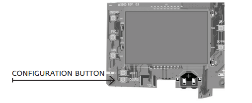
Accessing the Configuration Screen
- Ensure the thermostat is powered and the faceplate removed;
- Press the config button;
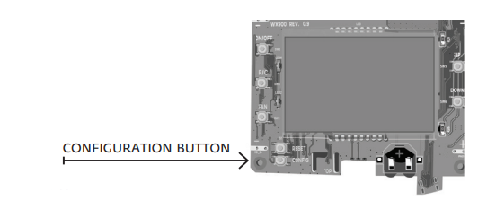
NOTE: You can access Thermostat Configuration settings at any time by pressing the “Configuration” button.
The thermostat configuration screens have a 30-second time-out. If no action is taken within (30) seconds, the thermostat will exit configuration settings.
NOTE: When the thermostat is connected to a network, the equipment and the energy-saving settings configured on the thermostat will be overridden by settings configured online.
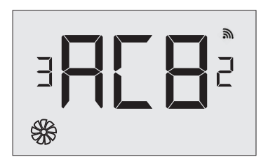
Pairing the Thermostat and HVAC Controller
The thermostat and HVAC Controller must be paired during installation. The thermostat will search for the closest HVAC Controller to it and display the unique HVAC Controller ID. The HVAC Controller ID is located on the case.
THE WIRELESS CONTROLLER MUST BE LINKED TO A THERMOSTAT IN THE SAME ROOM. ONLY INSTALL ONE ROOM AT A TIME.
- Verify that the HVAC controller found by the thermostat matches the HVAC controller listed on the HVAC controller in the same room;
- Press the F|C button to pair the thermostat with the HVAC Controller displayed on the screen. The screen will display “SUCC” when the HVAC Controller has been paired successfully. If the HVAC Controller ID displayed on the screen is incorrect, press the FAN button to reject it;
- Press the F|C button to advance to the next configuration menu.
Setting the MESH ID
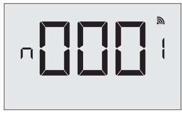
- Press the FAN button to advance to the next digit;
- Press the UP and DOWN buttons to increase or decrease the value;
- Press the F|C button to advance to the next menu.
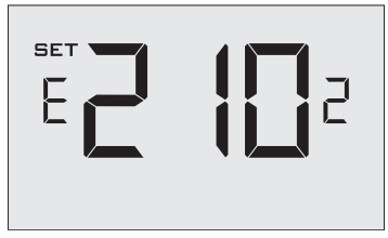
Entering the Room Number
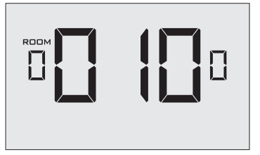
Enter the room number by changing the characters on the screen.
Available characters include digits 0-9 and letters A-F. To distinguish between two or more thermostats in the same unit, enter as follows:
- Thermostat 1: 00100
- Thermostat 2: 0100A
- Press the FAN button to advance to the next digit;
- Press the UP and DOWN buttons to increase or decrease the value;
- Press the F|C button to advance to the next menu.
Entering the room number correctly is crucial for the proper operation of thermostats with online management.
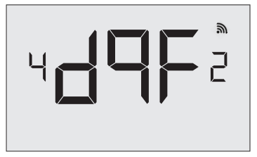
Configuring the Equipment Settings
Enter the equipment code by changing the digits on the screen. Refer to the table below.
- Press the FAN button to advance to the next equipment setting.
- Press the UP and DOWN buttons to increase or decrease the value;
- Press the F|C button to advance to the next menu.
| Digit | Setting #1 Compressor Type | Setting #2 Electric Heat | Setting #3 Reversing Valve | Setting #4 Fan Speed |
| 0 | No Compressor | No Electric Heat | O/B Contact is energized
to cool* |
N/A |
| 1 | Heat Pump | Electric Heat* | O/B Contact is energized
to heat |
One Fan Speed* |
| 2 | Air Conditioner* | N/A | N/A | Two Fan Speeds |
|
3 |
N/A |
Three Fan Speeds | ||
*Indicates default setting.
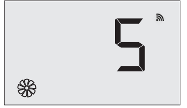
Configuring the Energy Saving Settings
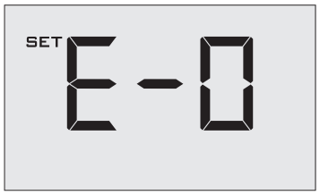
- Press the UP and DOWN buttons to increase or decrease the energy savings preset.
- Press the F|C button to advance to the next menu.
| Preset | Energy Savings Presets |
| E-0* | Energy Savings Off – No Temperature Setback |
| E-1 | Lowest Energy Savings |
| E-2 | Lower Energy Savings |
| E-3 | Standard Energy Savings |
| E-4 | Higher Energy Savings |
| E-5 | Highest Energy Savings |
*Indicates default setting.
Setting the thermostat clock
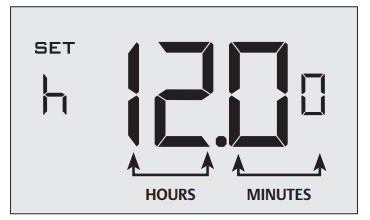
Set the thermostat clock to current time in 24h (Military Time) format.
- Press the FAN button to advance to the next digit;
- Press the UP and DOWN buttons to increase or decrease the digits
- Press the F|C button to advance to the next menu.
Setting the clock correctly is crucial for the proper operation of the thermostat.
Testing the Thermostat
Following the thermostat configuration, test if the thermostat is controlling the HVAC unit.
- Ensure the thermostat is powered and the faceplate is on.
- Press the DOWN button to change the temperature set point below the current room temperature to confirm that the thermostat initiates air conditioning;
- Press the UP button to change the temperature set point above the current room temperature to confirm that the thermostat initiates heating;
- Change the fan speed by touching the FAN button to test if the thermostat is controlling the fan speed.
Thermostat Maintenance
Replacing Thermostat Batteries
The low battery indicator will be displayed on the thermostat screen when it is necessary to replace batteries in the thermostat.
Under normal operating conditions, new brand-name alkaline batteries will last for a period of approximately eighteen (18) months.
Please replace batteries every sixteen (16) months to ensure continuous thermostat operation.
To replace thermostat batteries:
- Remove the thermostat cover;
- Replace the two (2) AA-cell batteries (not supplied);
- Re-affix the thermostat cover;
- Press the ON/OFF button to start using the thermostat.
NOTE: The thermostat maintains all the “Thermostat Configuration” settings in non-volatile memory. There is no need to configure the thermostat again after battery replacement.
Configuring & Managing Accessories
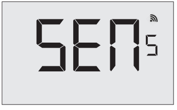
With the thermostat and HVAC unit powered, follow the sensor confi guration instructions to correctly confi gure the sensors.
- Remove the faceplate from the thermostat
- Press and hold the config button until SENS appears on the screen.
Activating a Sensor
- Remove the cover of the sensor(s) to be paired in the room;
- Insert one (1) AAA-cell battery into each sensor (not supplied);
- Press the button inside the sensor to make the sensor discoverable;*
- Press the FAN button to initiate the pairing procedure. This may take up to 30 seconds.
*The sensor(s) will remain discoverable for five (5) minutes after pressing the button inside the device. If the pairing process has not been completed within five (5) minutes of making sensor(s) discoverable, repeat this step.
Discovering an Active Sensor
The thermostat will display the first sensor discovered in the pairing process. Ensure that the unique device number displayed on the screen matches the unique ID found on the sensor.
- Press the F|C button to pair the discovered sensor to the HVAC Controller.
- Repeat this process as necessary for additional sensors.
If the sensor displayed on the screen is not the correct sensor to pair with the HVAC Controller, use the UP or DOWN buttons to find other discovered sensors. To start over, press the ON/OFF button to exit and refer back to page 24.
Configure the Functionality of a Sensor
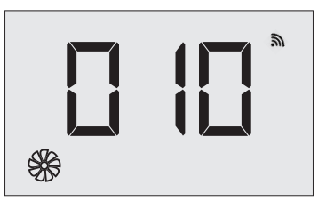
The thermostat allows the user to change the default functionality of the sensor. Use the table below to configure the desired functionality.
- Press the FAN button to advance to the next digit;
- Press the UP and DOWN buttons to increase or decrease the digit;
- Hold the F|C to save sensor settings.
| Functionality | Sensor Functionality Code |
| Occupancy Sensor | 100 |
| Sensor with Magnetic
door switch |
010* |
| Temperature Sensor | 001 |
*Indicates default setting.
Completing the Sensor Setup
The thermostat will count down from thirty (30) seconds. If the sensor has successfully paired, the thermostat will display “SUCC”. If the sensor did not pair successfully, the display will read “FAIL”, and the process must be repeated.
- Press the ON/OFF button to exit the sensor setup screen.
Technical Specifications
| Case Dimensions (Imperial) | 4.015 x 5.5118” x 0.925” | 4.84” x 2.76” x 1.02” |
| Case Dimensions (Metric) | 102mm x 140mm x 23.5mm | 123mm x 70mm x 26mm |
| Screen Dimensions (Imperial) | 3.625″ x 2.125″ | N/A |
| Screen Dimensions (Metric) | 92mm x 54mm | N/A |
| Operating Voltage | 3V DC – 2 “AA” Cell Batteries | 24V |
| Control Outputs | Fan High (GH) | |
| Fan Low (GL) | ||
| Compressor (Y) | ||
| Heat Pump (OB) | ||
| Electric Heat (W2) | ||
| Occupancy Out (AUX) | ||
| Occupancy Sensor Beam Width | ±47° (94°) | N/A |
| Wireless Frequency | 900MHz | 900MHz |
| Temperature Accuracy | ±1°F | N/A |
| FCC ID | XEYWX-DB | XEY-ZX-LV |
| IC | 8410A-WXDB | 8410A-ZXLV |
Troubleshooting
Error Codes
- ERR 1 Thermostat Temperature Sensor Hardware Defect
- ERR 2 Thermostat Radio Hardware Defect
- ERR 3 Thermostat Radio Software Defect
- ERR 4 No link with the HVAC Controller
- ERR 5 Thermostat Memory Defect
Troubleshooting Guide
Restoring Factory Settings
If there are reported errors or configuration issues, the user may restore factory settings to return the thermostat to its default parameters.
Procedure
- Power down the thermostat by either removing the batteries or cutting power to the thermostat;
- Remove the faceplate of the thermostat;
- Press and hold the CONFIG button located on the control board inside the thermostat while simultaneously powering the thermostat;
- Release the CONFIG button once the thermostat powers up;
- If the master reset was successful, the thermostat will display 12:00 and the thermostat must be re-configured. Please refer to pages 14-22 of this manual.
Contact Verdant technical support if the issues are not resolved.
APPENDIX 1 – Energy Saving Presets
| Level 0 | Level 1 | Level 2 | Level 3 | Level 4 | Level 5 | |
| Fan Control Mode | AUTO | AUTO | AUTO | AUTO | AUTO | AUTO |
| 1st Stage Differential Heat | 0.5 | 0.5 | 0.5 | 0.5 | 0.5 | 0.5 |
| 2nd Stage Differential Heat | 1 | 1 | 1 | 2 | 2 | 2 |
| 1st Stage Differential Cool | 0.5 | 0.5 | 0.5 | 0.5 | 0.5 | 0.5 |
| Guest Occupancy Threshold | 0 | 5 | 5 | 5 | 5 | 5 |
| Night Occupancy Threshold | 1 | 1 | 1 | 1 | 1 | 1 |
| Force 2nd Stage Heating After | 30 | 30 | 30 | 30 | 30 | 30 |
| Night Occupancy Start | 18 | 19 | 20 | 21 | 22 | 23 |
| Night Occupancy End | 12 | 11 | 10 | 9 | 8 | 7 |
| Recovery Time | 0 | 15 | 20 | 25 | 30 | 0 |
| Recovery Temperature Heat | 70 | 69 | 68 | 67 | 66 | 65 |
| Setback Delay – Heat | 0 | 30 | 25 | 20 | 15 | 10 |
| Minimum Setback Temperature | 67 | 66 | 65 | 64 | 63 | 62 |
| Setback Delay – Cool | 0 | 30 | 25 | 20 | 15 | 10 |
| Maximum Setback Temperature | 72 | 74 | 76 | 78 | 80 | 82 |
| Recovery Temperature Cool | 71 | 72 | 73 | 74 | 75 | 76 |
| Minimum Set point | 64 | 64 | 65 | 66 | 67 | 68 |
| Maximum Set point | 82 | 82 | 80 | 78 | 76 | 74 |
| Temperature Control Mode | AUTO | AUTO | AUTO | AUTO | AUTO | AUTO |
| Auto Changeover Set Point Offset Dead Band) | 1 | 1 | 1 | 1 | 1 | 1 |
| Auto Restore | OFF | ON | ON | ON | ON | ON |
| Setback Set Points | OFF | ON | ON | ON | ON | ON |
| Automatic Humidity Control | ON | ON | ON | ON | ON | ON |
| Temperature Calibration | 0 | 0 | 0 | 0 | 0 | 0 |
APPENDIX 2 – Glossary
- “Automatic Fan Control Mode” – fan runs only when there is a demand for heating or cooling; “Manual Fan Control Mode” – guest can select between automatic or continuous fan operation;
- “Minimum Setpoint” – the minimum temperature that a guest can request;
- “Maximum Set point” – the maximum temperature that a guest can request;
- “Auto Changeover Set Point Offset” – the difference between the guest-selected set point and the heat and cool changeover temperatures;
- “1st Stage Differential – Heat” – the temperature that the thermostat has to sense between the automatic changeover temperature for heat and the room temperature before a call for the 1st stage heating is initiated;
- “2nd Stage Differential – Heat” – the difference between 1st stage heating temperature and room temperature before the 2nd stage heating is initiated;
- “1st Stage Differential – Cool” – the temperature that the thermostat has to sense between the automatic changeover temperature for cool and the room temperature before a call for the 1st stage cooling is initiated;
- “Forced 2nd Stage Heating” – number of minutes 1st stage heating will run before 2nd stage heating is automatically initiated if the guest set point is not reached and the 2nd stage heating is not initiated through differential settings
- “Temperature Recovery Time” – the maximum period of time allowed for restoring the “Recovery Temperature”;
- “Recovery Temperature” – the room temperature that needs to be restored within the “Temperature Recovery Time”;
- “Maximum Setback Temperature” – the highest room temperature allowed when the thermostat is in the setback mode;
- “Minimum Setback Temperature” – the lowest room temperature allowed when the thermostat is in the setback mode;
- “Temperature Setback Delay” – the length of time for which the room that is in the guest occupancy mode needs to be unoccupied before the temperature setback is initiated;
- “Incidental Occupancy Threshold” – the minimum period of time (in minutes) for which occupancy needs to be detected in order to enter the “Guest Occupancy” mode;
- “Night Occupancy Threshold” – the minimum period of time during the “Night Occupancy” period for which occupancy needs to be detected in order to enter the “Night Occupancy” mode;
- “Night Occupancy Period” – The period of time during the day during which the “Night Occupancy” mode can be activated if occupancy longer than the “Night Occupancy Threshold” is detected;
- “Auto Restore On” – thermostat will restore the most recent guest settings when new occupancy is detected;
- “Auto Restore Off” – thermostat will NOT restore the most recent guest and will remain turned off settings when new occupancy is detected;
- “Setback Set points On” – thermostat will maintain setback temperatures when room is unoccupied;
- “Setback Set points Off” – thermostat will NOT maintain setback temperatures when room is unoccupied;
- “Incidental Occupancy” – occupancy shorter than the
- “Incidental Occupancy Threshold”;
- “Guest Occupancy” – occupancy longer than the
- “Incidental Occupancy Threshold”;
- “Temperature Setback” – thermostat maintains setback temperatures and not the guest set point temperature in order to save energy;
- “Night Occupancy Mode” – thermostat status during which setback mode is disabled if occupancy is longer than
- “Night Occupancy Threshold” is detected within the
- “Nigh Occupancy” period;
- “Automatic Temperature Changeover” – thermostat automatically activates heating or cooling to maintain the desired room temperature;
- “External Thermostat” (Class 2) mode – HVAC unit setting allowing it to be controlled by a remote thermostat;
Warranty Information
For the most recent warranty information, please visit www.verdant.co/verdant-warranty.
FCC
THIS DEVICE COMPLIES WITH PART 15 OF THE FCC RULES. OPERATION IS SUBJECT TO THE FOLLOWING TWO CONDITIONS:
- THIS DEVICE MAY NOT CAUSE HARMFUL INTERFERENCE, AND (
- THIS DEVICE MUST ACCEPT ANY INTERFERENCE RECEIVED, INCLUDING INTERFERENCE THAT MAY CAUSE UNDESIRED OPERATION.
THE MANUFACTURER IS NOT RESPONSIBLE FOR ANY RADIO OR TV INTERFERENCE CAUSED BY UNAUTHORIZED MODIFICATIONS TO THIS EQUIPMENT. SUCH MODIFICATIONS COULD VOID THE USER’S AUTHORITY TO OPERATE THE EQUIPMENT
This device complies with Industry Canada license-exempt RSS standard(s). Operation is subject to the following two conditions:
- this device may not cause interference, and
- this device must accept any interference, including interference that may cause undesired operation of the device.
Under Industry Canada regulations, this radio transmitter may only operate using an antenna of a type and maximum (or lesser) gain approved for the transmitter by Industry Canada. To reduce potential radio interference to other users, the antenna type and its gain should be so chosen that the equivalent isotropically radiated power (e.i.r.p.) is not more than that necessary for successful communication.
COVERED BY ONE OR MORE OF THE FOLLOWING PATENTS. US PATENTS: 8,369,994; 8,141,791; 7,918,406; 7,232,075; 7,185,825; 7,156,318; 7,152,806; 7,145,110; 7,050,026; 7,028,912; 6,902,117; 6,789,739; 6,786,421; 6,619,555; 6,581,846; 6,578,770; 7,838,803; 7,841,542; D556,061; D518,744; RE40,437; CANADIAN PATENTS: 2,633,113; 2,633,200; OTHER PATENTS PENDING.
Verdant Environmental Technologies, Inc. reserves the right to make changes, without notice, in design or components.
Product appearance may vary. © Verdant Environmental Technologies, Inc. 2020.
Printed in Canada. V.1 JUNE 2020
REFERENCE
Download Manual
Verdant VXDB-TW-KT-W Wireless Thermostat Installation Manual
![]()
Verdant VXDB-TW-KT-W Wireless Thermostat Installation Manual