
VR 91 Programmable Thermostat

Safety
General safety information
Risk caused by inadequate qualifications
Assembly and disassembly, installation, start-up, maintenance, repairs, and decommissioning must only be carried out by a competent person who is sufficiently qualified to observe all of the instructions that come with the product, to proceed in accordance with the current state-of-the-art, and to comply with all applicable directives, standards, laws, and other regulations.
For the competent person
Risk of material damage caused by frost
- Do not install the product in rooms prone to frost.
Requirements for lines
- Use standard commercial lines for the wiring.
- Minimum cross-section:
- ≥ 0.75 mm²
- Maximum line length:
- ≤ 125 m
Intended use
In the event of inappropriate or improper use, damage to the product and other properties may arise. The product enables a zone to be controlled remotely via an eBUS interface. The following components are required for operation:
- VRC 700 Intended use includes the following: observance of accompanying
- operating, installation, and servicing instructions for the product and any other system components installing and fitting the product in accordance with the product and system
approval - compliance with all inspection and maintenance conditions listed in the instructions.
Intended use also covers installation in accordance with the IP class. Any other use that is not specified in these instructions, or uses beyond that specified in this document shall be considered improper use. Any direct commercial or industrial use is also deemed to be improper.
Caution
Improper use of any kind is prohibited.
For the operator
Notes on the documentation
Observing other applicable documents
- You must observe all operating instructions
enclosed with the system components.
Storing documents
- Keep this manual and all other applicable documents safe for future use.
Applicability of the instructions
These instructions apply only to: VR 91 – article number
Great Britain 0020171334
Product Overview
CE label
The CE label shows that the products comply with the basic requirements of the applicable directives as stated on the identification plate. The declaration of conformity can be viewed at the manufacturer’s site.
Design of the product
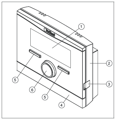
- Display
- Wall-mounting base
- Diagnostics socket
- Wall-mounting base cover
- Selection button
- Rotary knob
Identification plate
The identification plate is located on the product’s PCB and cannot be accessed from the outside once the product has been mounted on the wall. The identification plate contains the following information:
| Information on the
identification plate |
Meaning |
| Serial number | For identification |
| VR 91 | Unit designation |
| V | Operating voltage |
| mA | Current consumption |
| Product complies with European stand-
ards and directives |
|
| Proper disposal of
the product |
Serial number
The 10-digit article number can be found in the serial number. You can view the serial number under Menu → Information Serial number. The article number is found in the second line of the serial number.
Control function
The product is a wired remote control unit. Communication takes place over a 2-core eBUS line. You can use the product to set and/or change the functions of a zone, such as the operating mode or times and temperatures.
Operating
You can only operate the remote control unit in combination with the VRC 700 controller. This means that it is also necessary to read through the operating instructions for the VRC 700 controller.
The operating instructions for the controller will provide you with
- Information on the operating structure.
- Information on the operating concept with examples.
- A detailed description of the operating and display functions that the remote control unit also has.
- Overview of operating modes and functions
Operating modes (→ Page 12)
Operating levels (→ Page 12)
Service message
When maintenance is required, Maintenance and the symbol will appear in the remote control unit display. You can read the specific maintenance messages on the controller display and find out which measures you need to take from the controller operating instructions.
Fault message
If a fault occurs in the heating installation, will appear in the display together with a fault message. The competent person must clear or rectify the fault in the heating installation, otherwise, it could cause material damage or make the heating installation malfunction. Inform a competent person. If you would like to see the basic display in the display again, press the left-hand selection button Back. You can call up the current fault messages under Menu → Information → System status → Fault status → Fault list.
Detecting and rectifying faults
| Fault | Cause | Remedy |
| Display is dark | Appli- ance fault | – Switch off the
mains switch on all heat generators for approx. 1 minute and then switch them on again – Inform the competent person if the fault persists or if you do not have the option of switching off the heat gener- ator. |
| No changes in the display when the rotary knob is turned | ||
| No changes in the display via the selec- tion buttons are pressed | ||
| Lines appear instead of setting and read-out val- ues in the
display |
Commu- nication fault | Inform the skilled tradesman |
Caution.
Risk of material damage caused by unsuitable cleaning agents.
- Do not use sprays, scouring agents, detergents, solvents, or cleaning agents that contain chlorine.
- Clean the casing with a damp cloth and a little solvent-free soap.
Decommissioning
Replacing the remote control unit
The heating installation must be shut down before replacing its remote control unit.
- This work should be carried out by a competent person.
Recycling and Disposal
- The competent person who installed your product is responsible for the disposal of the packaging. If the product is identified with this symbol:
- In this case, do not dispose of the product with household waste.
- Instead, hand in the product to a collection center for old electrical or electronic appliances.
- If the product contains batteries that are marked with this symbol, these batteries may contain substances that are hazardous to human health and the environment.
- In this case, dispose of the batteries at a collection point for batteries.
Guarantee and customer service
Guarantee
We only grant Vaillant manufacturers warranty if a suitably qualified engineer has installed the system in accordance with Vaillant instructions. The system owner will be granted a warranty in accordance
with the Vaillant terms and conditions. All requests for work during the guarantee period must be made to Vaillant Service Solutions (0870 6060 777).
Customer service
To ensure regular servicing, it is strongly recommended that arrangements are made for a Maintenance Agreement. Please contact Vaillant Service Solutions (0870 6060 777) for further details.
Technical data
| Max. operating voltage | 24 V |
| Current consumption | < 50 mA |
| Supply line cross-section | 0.75
… 1.5 mm² |
| Level of protection | IP 20 |
| Protection class | III |
| Maximum permitted ambient
temperature |
0 … 60 ℃ |
| Curr. room air hum. | 35 … 95 % |
| Height | 115 mm |
| Width | 147 mm |
| Depth | 50 mm |
For the competent person
Notes on the documentation Observing other applicable documents
- You must observe all the operating and installation instructions are included with the system components.
Storing documents
- Pass these instructions and all other applicable documents on to the system operator.
Product overview
Checking the scope of delivery
| Quant-
ity |
Contents |
| 1 | Remote control unit |
| 1 | Fastening material (2 bolts and 2
wall plugs) |
| 1 | Operating and installation instruc-
tions |
Installing the remote control unit in a living room
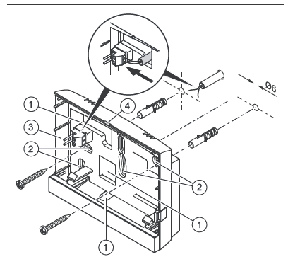
- Mount the remote control unit on an interior wall of the main living room in a position that ensures accurate measurement of the room temperature. Installation height: 1.5 m
- Openings for cable duct
- Mounting holes
- Pin header with terminals for the eBUS line
- Opening slot
- Screw on the wall-mounting base as shown in the illustration.
- Connect the eBUS line
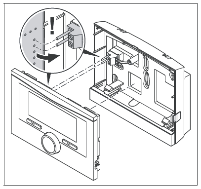
- Carefully push the remote control unit into the wall-mounting base.
Electrical installation
When connecting the eBUS line, there is no need to pay attention to the polarity. If the two connections are switched around, communication is not affected.
Connecting the remote control unit to a heat generator
- At lengths of over 10 m, 230 V supply lines must be laid separately from the bus lines.
- When opening the electronics box in the heat generator, proceed as described in the installation instructions for the heat generator.
Conditions: The heat generator is not connected to the eBUS via the VR 32.
- Connect the eBUS line to the eBUS terminals in the wall-mounting base of the remote control unit.
- Connect the eBUS line to the eBUS terminals in the heat generator.
Start-up
When the system is started up for the first time after completing the electrical installation, the installation assistants for the components and the VR 91 remote control unit will start automatically. All settings that you have applied using the installation assistant can be changed again at a later date via the level for the operator and competent persons. Installation assistant (→ Page 14)
Selecting setting values
Conditions: Settings in the remote control unit
- Select the required language in the Language function.
- Enter an address for the remote control unit to communicate within the Remote control address function.
Conditions: Settings in the controller
- If you would also like to use the room temperature sensor in the remote control unit, select Temp. mod. or Thermostat. value in the Room temp. mod. function.
- Specify in which zone the remote control unit has been installed.
- Scroll through the display to the zone in which the remote control unit has been installed.
- Set the value to Yes in the Zone activated function for this zone.
- In the Zone assignment function in this zone, assign the address for the remote control unit that should be triggered.
Handing over to the operator
- You must inform the operator about how to handle their product and how it works.
- Provide the operator with all relevant instructions and unit documentation for safe keeping.
- Go through the operating instructions with the operator.
- Answer any questions the operator may have.
- In particular, draw the operator’s attention to the safety information that they must follow.
- Inform the operator that room air must be able to circulate freely around the product and that it should not be covered by furniture, curtains, or other objects.
- Inform the operator that all the radiator valves in the room where the product is installed must be fully open.
Operating
You can find the operator setting and readout options in the appendix.
Operating modes (→ Page 12)
Operating levels (→ Page 12)
The operating instructions for the controller will provide you with
- Information on the operating structure.
- Information on the operating concept with examples.
- A detailed description of the operating and display functions that the remote control unit also has.
Overview of functions
Installer level (→ Page 14)
- Reading the fault status
Menu → Installer level → System configuration
[System —-] → Fault status - This function allows you to read the status of the heating installation. If there are no faults, the message No fault appears here. If there is a fault, the status of The fault list is displayed. If you press the right-hand selection button, fault messages are displayed.
Reading the software version
Menu → Installer level → System configuration [System —-] → Control modules You can use this function to read the software versions of the remote control unit.
Setting the address for the remote control unit
Menu → Installer level → System configuration [System —-] → Remote control address You can use this function to set the address for the remote control unit. Every remote control unit has a unique address,
starting with Address 1. Increase the number in the address consecutively for each additional remote control unit used.
Fault messages and faults
Fault messages
If a fault occurs in the heating installation, will appear in the display together with a fault message. You can also read all current error messages under the following menu point: Menu → Installer level → System configuration [System —-] → Fault status – If a fault has occurred, the Fault list will appear in the Fault status function. Press the right-hand selection button to display a list of fault messages
Overview of fault messages and faults
Fault messages (→ Appendix B.3)
Faults (→ Appendix B.4)
Decommissioning
Replacing the product
- Decommission the heating installation if you want to replace the product.
- Decommission the heat generator, as described in the heat generator’s installation instructions.
Removing from the wall
- Insert the screwdriver into the slot on the wall-mounting base.
- Carefully lever the remote control unit from the wall-mounting base.
- Unfasten the eBUS line from the pin of the header on the remote control unit and from the terminal block on the heat generator
- Unscrew the wall-mounting base from the wall.
Customer service
Customer service addresses can be found in the installation instructions for the controller.
Appendix
For the operator Operating modes
| Operating mode | Setting | Default setting |
| Operating mode | ||
| Heating | Off, Auto, Day, Set-back | Auto |
| Cooling | Off, Auto, Day | Auto |
| Advanced functions | ||
| 1 day at home | Active | – |
| 1 day away from home | Active | – |
| 1 x ventilation boost | Active | – |
| Party | Active | – |
Operating levels
A detailed description of the functions can be found in the operating instructions for the controller.
| Setting level | Values | Unit | Increment, select | Default
setting |
|
| Min. | Max. | ||||
| Information → System status → | |||||
| System —- | |||||
| Fault status | Current value | No fault, Fault list | |||
| Curr. room air hum. | Current value | % | |||
| Current dew point | Current value | ℃ | |||
| ZONE1 —- | |||||
| Day temp. Heating | Current value | ℃ | 0.5 | 20 | |
| 5 | 30 | ||||
| Day temp. Cooling | Current value | ℃ | 0.5 | 24 | |
| 15 | 30 | ||||
| Set-back temp. heat. | Current value | ℃ | 0.5 | 15 | |
| 5 | 30 | ||||
| Room temperature | Current value | ℃ | |||
| Information → Contact details → | |||||
| Installer Phone number | Current values | ||||
| Information → Serial number | |||||
| Unit number | Permanent value | ||||
| Desired temperatures → ZONE1 → | |||||
| Day temp. Heating | 5 | 30 | ℃ | 0.5 | 20 |
| Day temp. Cooling | 15 | 30 | ℃ | 0.5 | 24 |
| Set-back temp. heat. | 5 | 30 | ℃ | 0.5 | 15 |
| Setting level | Values | Unit | Increment, select | Default
setting |
|
| Min. | Max. | ||||
| Time programmes → ZONE1: Heating → | |||||
| Individual days and blocks | Monday, Tues- day, Wednesday, Thursday, Friday, Saturday, Sunday and Monday – Fri- day, Saturday – Sunday, Monday –
Sunday |
Mo – Fr:
06:00- 22:00 Sa: 07:30- 23:30 Su: 07:30- 22:00 |
|||
| Time period 1: Start – End
Time period 2: Start – End Time period 3: Start – End |
00:00 | 24:00 | h:min | 00:10 | |
| Time programmes → ZONE1: Cooling → | |||||
| Individual days and blocks | Monday, Tues- day, Wednesday, Thursday, Friday, Saturday, Sunday and Monday – Fri- day, Saturday – Sunday, Monday –
Sunday |
Mo – Fr:
06:00- 22:00 Sa: 07:30- 23:30 Su: 07:30- 22:00 |
|||
| Time period 1: Start – End
Time period 2: Start – End Time period 3: Start – End |
00:00 | 24:00 | h:min | 00:10 | |
| Days away scheduling → | |||||
| Start | 01.01.01 | 31.12.99 | dd.mm.yy | Day.Month.Year | 01.01.14 |
| End | 01.01.01 | 31.12.99 | dd.mm.yy | Day.Month.Year | 01.01.14 |
| Temperature | 5 | 30 | ℃ | 1 | 15 |
| Days at home scheduling → | |||||
| Start | 01.01.01 | 31.12.99 | dd.mm.yy | Day.Month.Year | 01.01.14 |
| End | 01.01.01 | 31.12.99 | dd.mm.yy | Day.Month.Year | 01.01.14 |
| Basic settings → Language → | |||||
| Setting level | Values | Unit | Increment, select | Default
setting |
|
| Min. | Max. | ||||
| Selectable language | Deutsch | ||||
| Basic settings → Display → | |||||
| Display contrast | 1 | 15 | 1 | 9 | |
| Button lock | Off, On | Off | |||
| Preferred display | Heating, Cooling | Heating | |||
| Basic settings → Offset → | |||||
| Room temperature | -3.0 | 3.0 | K | 0.5 | 0.0 |
| Basic settings → Enter zone name → | |||||
| ZONE1 | 1 | 10 | A to Z, 0 to 9, space | ZONE1 | |
| Installer level → | |||||
| Enter code | 000 | 999 | 1 | 000 | |
For the competent person
Installation assistant
| Setting | Values | Increment, select | Default setting | |
| Min. | Max. | |||
| Language | Languages available
for selection |
Deutsch | ||
| Remote control address | 1 | 8 | 1 | 1 |
Installer level
| Setting level | ||
| Installer level → | ||
| Enter code | ||
| Installer level → System configuration → | ||
| System —- | ||
| Fault status | ||
| Controller modules | ||
| Remote control address | ||
| * If there is no fault, the status is No fault. If there is a fault, Fault list appears and you can
read the fault message in the Fault messages section. |
||
Fault messages
| Message | Possible cause | Measure |
| Room temp. sensor
fault |
The room temperature
sensor is defective |
1. Replace the room temperature sensor. |
| No zone assignment for the remote con- trol or the controller | No remote control
address |
1. Set the correct address on the remote con-
trol unit. |
| No zone assignment | 1. Set the correct address for the remote con-
trol unit on the controller. |
|
| System fault | Faults in the system | 1. Assess the fault messages in the control-
ler. |
Faults
| Symptom | Possible cause | Measure |
| Display remains dark | Software error | 1. Switch the mains switch on the heat gener- ator that feeds the controller off and back
on again. |
| No power at the heat
generator |
1. Check the power supply of the heat gener-
ator that feeds the controller. |
|
| The product is defect-
ive |
1. Replace the product. | |
| No changes in the display when the rotary knob is turned | Software error | 1. Switch the mains switch on the heat gener- ator that feeds the controller off and back
on again. |
| The product is defect-
ive |
1. Replace the product. | |
| No changes in the display when the se- lection buttons are pressed | Software error | 1. Switch the mains switch on the heat gener- ator that feeds the controller off and back
on again. |
| The product is defect-
ive |
1. Replace the product. | |
| Lines appear instead of set and read-out
values |
Communication fault | 1. Check the plug connection.
2. Replace the cable. |
Vaillant Ltd
Nottingham Road Belper Derbyshire DE56 1JT
Telephone 44 84 56 02 29 22 Vaillant Service Solutions 44 807 06 06 07 77
Spares Technical Enquiries 44 17 73 59 66 15
[email protected] [email protected] These instructions, or parts thereof, are protected by copyright and may be reproduced or distributed only with the manufacturer’s written consent
REFERENCE:
DOWNLOAD MANUALS:
Vaillant VR 91 Programmable Thermostat Installation Instructions
![]()
Vaillant VR 91 Programmable Thermostat Installation Instructions
Leave a Reply