Trane TCONT600AF11MA Programmable Thermostat Comfort Control

Installation tips
Install the Comfort Control about 5 feet (1.5m) above the floor in an area with good air circulation at an average temperature.

Do not install in locations where the Comfort Control can be affected by:
- Drafts or dead spots behind doors and in corners
- Hot or cold air from ducts
- Sunlight or radiant heat from appliances
- Concealed pipes or chimneys
- Unheated/uncooled areas such as an outside wall behind the Comfort Control
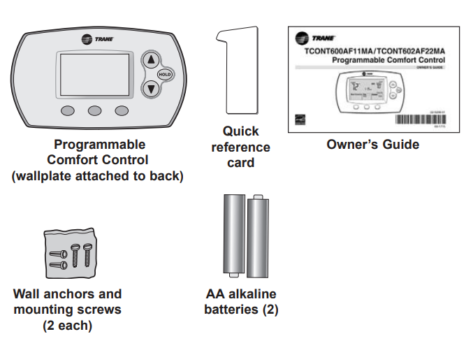
Pre-installation checklist
Package contents
Check to make sure your package includes the following items:
Required tools & supplies
- No. 2 Phillips screwdriver
- Small pocket screwdriver
- Drill
- Drill bit (3/16” for drywall, 7/32” for plaster)
- Hammer
- Pencil
- Electrical tape
- Level (optional)
Wallplate installation
Remove the wallplate from the Comfort Control as shown at left, then follow directions below for mounting.
- Insert quick reference card in slot in back of Comfort Control.
- Pull wires through wire hole.
- Position wallplate on wall, level and mark hole positions with pencil.
- drill holes at marked positions as shown below, then tap in supplied wall anchors.
- Place wallplate over anchors, insert and tighten mounting screws.


Wiring
CAUTION: ELECTRICAL HAZARD. Can cause electrical shock or equipment damage. Disconnect power before wiring.
Wiring
- loosen screw terminals, insert wires into terminal block, then re-tighten screws.
- Push excess wire back into the wall opening. Keep wires in shaded area as shown at left.
- Plug the wall opening with nonflammable insulation to prevent drafts from affecting Comfort Control operation.

Terminal Designations
- G Fan relay.
- W (O) Heat relay or changeover valve terminal for heat pumps.
- B Common wire from the secondary side of the cooling system transformer.
- Y Compressor contactor.
- R Heating power. Connect to the secondary side of the heating system transformer.
- Rc Cooling power. Connect to the secondary side of the cooling system transformer.
NOTES - R & Rc terminals
In a single-transformer system, leave metal jumper in place between R & Rc. Remove metal jumper if two-transformer system. - B terminal
- B is the common wire terminal.
- W (O) terminal
If Comfort Control is configured for a heat pump in the Installer Setup, changeover valve is configured for cool (“O” factory setting).
Wire specifications
Use 18- to 22-gauge thermostat wire. A shielded cable is not required.
Wiring diagrams
- Factory-installed jumper. Remove for 2-transformer systems only.
Provide Power Supply disconnect means and overload protection as required. - In Installer Setup, set system type to Heat Pump.

Power options & mounting
- AC Power

The Comfort Control must be powered by 24 VAC power. To wire the Comfort Control for AC power, connect the common side of the cooling transformer to the “B” terminal as shown at left. Important: Remove R/Rc jumper for 2-transformer systems only. (See wiring diagram on page 5.) - Battery Backup Power
The Comfort Control can be powered by backup batteries when used with AC power. During power interruptions, the batteries will save time/day settings and power the display.
After installation, batteries can be changed without removing the Comfort Control from the wall (see page 10).
- To Mount Comfort Control
Align the 4 tabs on the wallplate with corresponding slots on the back of the Comfort Control, then push gently until the Comfort Control snaps in place.
Installer setup
Follow the procedure below to configure the Comfort Control to match the installed heating/cooling system, and customize feature operation as desired.

| 1 | System type | 0 | Gas, oil or electric heat with air conditioning |
| 1 | Heat pump | ||
| 2
3 |
Heat only (2-wire systems/power to open & close zone valves/ normally open zone valves)
Heat only with fan |
||
| 4 | Cool only | ||
| 3 | Fan control | 0 | Gas or oil furnace — equipment controls fan in heating |
| (heating) | 1 | Electric furnace — Comfort Control controls fan in heating | |
| 5 | Heating cycle rate | 5 | For gas or oil furnaces of less than 90% efficiency |
| (CPH: cycles/hour) | 1 | For steam or gravity systems | |
| 3 | For hot water systems & furnaces of over 90% efficiency | ||
| 9 | For electric furnaces
[Other cycle rate options: 2, 4, 6, 7, 8, 10, 11 or 12 CPH] |
||
| 9 | Compressor cycle rate (CPH) | 3 | Recommended for most compressors
[Other cycle rate options: 1, 2, 4, 5 or 6 CPH] |
| 12 | System setting | 0 | Manual changeover (Heat/Cool/Off) |
| adjustment | 1 | Auto changeover (Heat/Cool/Auto/Off) **See page 9 | |
| 2 | Auto changeover only (Auto) **See page 9 | ||
| 13 | Adaptive Intelligent | 1 | On **See page 9 |
| Recovery™ | 0 | Off | |
| 14 | Temperature | 0 | Fahrenheit |
| display | 1 | Celsius | |
| 15 | Compressor protection | 5 | Five-minute compressor off time **See page 9 [Other options: 0, 1, 2, 3 or 4-minute off time] |
| 16 | Schedule format | 0 | 5/2 (programmable weekdays and weekends) |
| 1 | 5/1/1 (weekdays, Saturday & Sunday programmable) | ||
| 27 28 31 | Heat temperature range stops
Cool temperature range stops |
90 | Highest heating temperature setting 4 0-89 Heating temperature range (increments of 1°F, or 0.5°C) 60 Lowest cooling temperature setting 6 1-99 Cooling temperature range (increments of 1°F, or 0.5°C) 1 Cooling Droop 2 Cooling Droop with Comfort-RTM (15 seconds Fan Delay) 3 Cooling Droop with Comfort-RTM (30 seconds Fan Delay) 0 None |
Follow the procedure below to test the heating, cooling and fan

| 10 | Heating system | 0 | Heat and fan turn off. |
| 1 | Heat turns on. Fan also turns on immediately if Function 1 or 3 is set to “1” (see page 7). | ||
| 30 | Cooling system | 0 | Compressor and fan turn off. |
| 1 | Compressor and fan turn on. | ||
| 40 | Fan system | 0 | Fan turns off. |
| 1 | Fan turns on. | ||
| 70 | Comfort Control | 71 | Software revision number (major revisions) |
| information | 72 | Software revision number (minor revisions) | |
| (for reference only) | 73 | Configuration identification code (major) | |
| 74 | Configuration identification code (minor) | ||
| 75 | Production configuration date code (week) | ||
| 76 | Production configuration date code (year) |
CAUTION: EQUIPMENT DAMAGE HAZARD
Compressor protection (minimum off time) is bypassed during testing. To prevent equipment damage, avoid cycling the compressor quickly.
Auto Changeover (Setup Function 12)

Auto Changeover is a feature used in climates where both air conditioning and heating are used on the same day. When the system is set to Auto, the Comfort Control automatically selects heating or cooling depending on the indoor temperature. Heat and cool settings must be at least 3 degrees apart. The Comfort Control will automatically adjust settings to maintain this 3-degree separation (called “deadband”). The 3-degree separation between heating and cooling set temperatures is fixed, and cannot be changed.
Adaptive Intelligent Recovery™ (Setup Function 13)
Adaptive Intelligent Recovery eliminates guesswork when setting your schedule. It allows Comfort Control to “learn” how long your furnace and air conditioner take to reach the temperature you want. Just set your program schedule to the time you want the house to reach your desired temperature. The Comfort Control then turns on the heating or cooling at just the right time to reach your scheduled temperature at your scheduled time.
For example: Set the Wake time to 6 am, and the temperature to 70°. The heat will come on before 6 am, so the temperature is 70° by the time you wake at 6.
Built-in compressor protection (Setup Function 15)

This feature helps prevent damage to the compressor in your air conditioning or heat pump system. Damage can occur if the compressor is re-started too soon after shutdown. This feature forces the compressor to wait for a few minutes before restarting. During the wait time, the message Cool On or Heat On (heat pumps only) will flash on the display. When the safe wait time has elapsed, the message stops flashing and the compressor turns on.
Quick reference to controls

Quick reference to display screen

Battery replacement

In case of difficulty
If you have difficulty with your Comfort Control, please try the suggestions below. Most problems can be corrected quickly and easily.
Display is blank
- Check the circuit breaker and reset if necessary.
- Make sure the power switch at the heating & cooling system is on.
- Make sure the furnace door is closed securely.
Temperature settings do not change
Make sure heating and cooling temperatures are set to acceptable ranges:
- Heat: 40° to 90°F (4.5° to 32°C).
- Cool: 60° to 99°F (15.5° to 37°C).
The heating system does not respond (“Heat On” appears on the screen)
- Check for 24 Vac at the equipment on the secondary side of the transformer between power and common. If voltage is not present, check the heating equipment to find the cause of the problem.
- Check for 24 Vac between the heat terminal (W) and the transformer common. If 24 Vac is present, the Comfort Control is functional. Check the heating equipment to find the cause of the problem.
- Check for loose or broken wires between the Comfort Control and the heating equipment.
The cooling system does not respond (“Cool On” appears on the screen)
- Check for 24 Vac at the equipment on the secondary side of the transformer between power and common. If voltage is not present, check the cooling equipment to find the cause of the problem
- Check for 24 Vac between the cooling terminal (Y) and the transformer common. If 24 Vac is present, the Comfort Control is functional. Check the cooling system to find the cause of the problem.
- Check for loose or broken wires between the Comfort Control and the cooling equipment.
The fan does not turn on in a call for heat
- Check Installer Setup, Function 3 (Fan Control), to make sure the fan control is properly set to match the type of system (see page 7).
Heat/cool both on at the same time, or heat does not turn off
- Check Installer Setup, Function 1 (System Type), to make sure it is set to match the installed heating/cooling equipment (see page 7).
- Check to make sure heating and cooling wires are not shorted together.
The heating equipment is running in cool mode
- Check Installer Setup, Function 1 (System Type), to make sure it is set to match the installed heating/cooling equipment (see page 7).
Cannot change system set to “Heat”
- Check Installer Setup, Function 1 (System Type), to make sure it is set to match the installed heating equipment (see page 7).
- Change Installer Setup, Function 12 (System Setting) to Manual or Auto Changeover (see page 7).
Cannot change the system set to “Cool”
- Check Installer Setup, Function 1 (System Type), to make sure it is set to match the installed cooling equipment (see page 7).
- Change Installer Setup, Function 12 (System Setting) to Manual or Auto Changeover (see page 7).
“Heat On” is not displayed
- Change the System Setting to Heat, and set the temperature level above the current room temperature.
“Cool On” is not displayed
- Change the System Setting to Cool, and set the temperature level below the current room temperature.
“Cool On” or “Heat On” is flashing
- Compressor protection timeout is engaged. Wait 5 minutes for the system to restart safely, without damage to the compressor.
Accessories & replacement parts
Please contact your distributor to order replacement parts.
- Battery holder..……………………………………………….Part Number THT02506
- Cover plate assembly..……………………………………Part Number BAYCOVR700A
(Use to cover marks left by old thermostats.)
Specifications
- Temperature Ranges
- Heat: 40° to 90°F (4.5° to 32°C)
- Cool: 60° to 99°F (15.5° to 37°C)
- Operating Ambient Temperature 32° to 120°F (0° to 48.9°C)
- Shipping Temperature -20° to 120°F (-28.9° to 48.9°C)
- Operating Relative Humidity 5% to 90% (non-condensing)
- Physical Dimensions
3-9/16” H x 5-13/16” W x 1-1/2” D
91 mm H x 147 mm W x 38 mm D
Electrical Ratings
- Terminal Voltage (50/60Hz) Running Current
- W (O) Heating 20-30 Vac 0.02-1.0 A
- Y Cooling 20-30 Vac 0.02-1.0 A
- G Fan 20-30 Vac 0.02-0.5 A
6200 Troup Highway
Tyler, TX 75711-9010
www.trane.com
® U.S. Registered Trademark • Patents Pending.
© 2006 American Standard All rights reserved
REFERENCE:
Download Manual:
Trane TCONT600AF11MA Programmable Thermostat Comfort Control Installation Instructions
OTHER MANUALS:
Trane TCONT600AF11MA Comfort Control Programmable THERMOSTAT OWNERS GUIDE
![]()
Trane TCONT600AF11MA Programmable Thermostat Comfort Control Installation Instructions