TRANE 1H/1C(p/n X13511535-01) Programmable Thermostats
This section provides general descriptive and procedural information intended for typical daily operators of the thermostat.
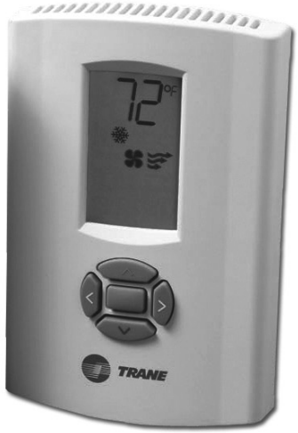
Icon Descriptions
Figure 36 describes the icons visible on the front of the thermostat.
Note: Except when the thermostat is powering up, when all of the icons are shown for 2 sec, only some of the icons will be visible at once.
Overview of Operation
If configured properly, both programmable and non-programmable thermostats will control HVAC equipment to maintain room temperature automatically
Non-ProgrammableThermostats
Non-programmable thermostats do not have timekeeping or scheduling capabilities.They will continue to maintain heating and/or cooling setpoints until an operator makes changes to the setup.Therefore, only the following tasks may be required performed:
- Change the system mode.
- Show or change the heating or cooling temperature setpoint.
- Change the fan mode.
Note: The system mode, temperature setpoints, and fan mode can each be individually locked to prevent users from changing them. If you see a on the display, you may need to unlock the setting before you change it (see “Locking or Unlocking Modes,” p. 40).
Changing the System Mode
Note: If you are unable to change the system mode, check the system type setting and the manual/auto changeover setting (see “Configuration,” p. 26) to verify that the thermostat is configured with heat and cool modes, and that it permits manually changing them.
Depending upon the model and system type, the thermostat can be set to one of five modes: Cooling, Heating, Emergency Heat, Auto, or Off.
 Cooling mode cools the room to bring it down to the cooling setpoint.
 Heating mode heats the room to bring it up to the heating setpoint.
 Emergency Heat mode heats the room according to the heating unit’s emergency heat mode settings.
 Auto mode switches automatically between heating and cooling modes as required.
 Off mode prevents the thermostat from requesting any heating or cooling regardless of the room temperature. Off mode also disables fan selection and prevents the user from changing the setpoint.
Note: The 1-Heat/1-Cool thermostat does not have Emergency Heat mode.
To change the system mode:
- Press
 The current mode flashes
- .Press
 or
or to select a mode.
 - Tap
 or wait 5 sec to save and exit.
Showing or Changing the Heating or CoolingTemperature Setpoint
To change the heating or cooling setpoint:
- Press
 or
or  once.This shows the active setpoint.
 - Within 5 sec:
- Press or to increase or decrease the setpoint.
- Press orto change between heat and cool setpoints if both are enabled.
- Press
- Tap or wait 5 sec to save and exit.
Changing the Fan Mode
Note: If you are unable to see the fan mode, check the system type setting in the installation configuration options to make sure that it is specified as a system with a fan.
There are two fan modes. Each are indicated by an icon on the display:
 Auto mode turns the fan on and off as needed according to equipment configuration.
 On runs the fan continuously.
To change the fan mode:
- Press > >.The current mode flashes
 .
. - Press orto change the mode. The selected mode flashes.
note: If you are unable to change the mode and flash, the mode is locked. See “Locking or Unlocking Modes,” p. 40.
 - Tap or wait 5 sec to save and exit.
Programmable Thermostats
Programmable thermostats contain all of the functionality of non-programmable thermostats, but they also keep track of the date, day of the week, and time of day for scheduling purposes.
Programming
This section describes how to program the thermostat after it has been installed and configured.
Setting theTime
The time must be set in the thermostat to ensure operation of the schedule.
Note: The date is set during configuration and the day of the week is calculated automatically according to the date.
To set the time:
- Press > > > > > .The hour flashes to indicate that it can be changed
 .
.
Note: The thermostat automatically returns to normal operating mode if no buttons are pressed for 10 sec. - Make changes to the hour and minute, as needed:
- Press orto switch between hours and minutes.The changeable option flashes to indicate that it can be changed.
- Press or to change the value of the option.
- Press
- Press and hold for 2 sec or wait 10 sec to apply the change and exit.
Scheduling
The thermostat can be configured for two periods (day and night) or four periods (morning, day, evening, and night).The chosen number of periods are applied to each day of the week when you program the thermostat. Each period can have a unique start time, heat setpoint, cool setpoint, and fan setting.
The groups of days can be one of the following:
- 1 day = all 7 days of the week follow the same schedule.
- 5+1+1 days = Monday – Friday all follow the same schedule; Saturday and Sunday each follow their own schedules.
- 5+2 days = Monday – Friday all follow the same schedule; Saturday and Sunday follow the same schedule, which is different than the Monday – Friday schedule.
- 7 days = Each day follows its own schedule.
Note: See “Configuration,” p. 26 to change the number of periods in a day or the grouping of days in the schedule.
If needed, you can use Table 9 to write down your schedule settings before you begin setting up the schedule.The default schedule is also shown in the table. Unless you program your own schedule settings, the thermostat follows the default schedule for all days of the week.

Weekly Operating ScheduleWorksheet
To set the schedule:
- Press > > > .The display shows only the following elements:
- Press.
Note: At this point, the thermostat is in schedule change mode. It returns to normal operating mode if no buttons are pressed for 45 sec. To manually exit schedule change mode, press and hold for 2 sec.
Note: If flashes and you are unable to enter schedule change mode, the mode is locked. See “Locking or Unlocking Modes,” p. 40.
 - Press orselect the day or days for which you want to set the schedule. The selected day or days flash.
- Press to accept the selection. , or starts flashing.
- Press orto select the period. The selected period starts flashing.
- Press to accept the selection. The start time starts flashing
 .
. - Press or select the start time. Time is increased or decreased in 10 min steps.
- Press to accept the selection. If there is a heat mode configured, the heat setpoint appears and its icons start flashing
 .
. - Press or select the heating setpoint.
- Press to accept the selection. If there is a cool mode configured, the cooling setpoint appears and its icons start flashing
 .
. - Press or to select the cool setpoint.
- Press to accept the selection. orstarts flashing.
- Press orselect the fan setting.
- to turn it on and off automatically
- to keep the fan on continuously
- Press to accept the selection. This completes the schedule settings for one period of one day of the week.
- Repeat Steps 3 through Step 14 once for each day and period you need to set.
Day-to-Day Operation
After a programmable thermostat is configured and the schedule is programmed, the thermostat automatically changes the setpoints and fan settings according to the schedule.However, there are some operator tasks that you may need or want to perform:
- Show setpoint or current temperature. You can temporarily or permanently switch the main display from the current temperature to the temperature setpoint. See “Showing the Setpoint or The temperature on Display,” p. 39.
- Set the system mode, which includes turning the system on or off, and switching between heating, cooling, and automatic heating and cooling. See “Changing the System Mode,” p. 34.
- Override the schedule. If an unexpected, one-time temperature setpoint or fan mode change is needed you can temporarily override the schedule. See “Timed Override (TOV) Mode,” p. 40.
- Lock or unlock.You can lock the thermostat buttons to prevent changes to the thermostat settings. See “Locking or Unlocking Modes,” p. 40.
Note: It is possible for a programmable thermostat to be configured to be a non-programmable thermostat. If installation configuration option #140 is set to 0, schedule programming capabilities will be absent.
Showing the Setpoint temperature on Display
Depending upon the value of configuration option #210, the large numeric display could show any of the following:
Figure 37. Display Options
| Value of configuration option #210 | Numeric display options
(press |
| 0 | The current local temperature, or the current or most recent temperature setpoint |
| 1 or 2 | The current local or remote indoor temperature or the current or most recent temperature setpoint |
| 3 | The current indoor temperature, the current or most recent temperature setpoint, or the current remote outdoor temperature, which only appears for 8 sec before reverting to current indoor temperature or setpoint |
To switch between the current temperature, “o dr” temperature, and the setpoint temperature, press and hold the![]() or
or ![]() buttons for 3 sec.The display will toggle as shown in Figure 37.
buttons for 3 sec.The display will toggle as shown in Figure 37.
Timed Override (TOV) Mode
During normal operation, the thermostat controls the HVAC equipment according to the schedule that is programmed into it.To permanently change the temperature setpoint or fan setting, make the change in the programmed schedule (see “Scheduling,” p. 36). However, a timed override can be used to temporarily change the current settings without making any change to the schedule.
To start a temperature setpoint override:
- Press or .The current temperature setpoint appears.
- Within 5 sec of Step 1, press to raise the setpoint or to lower the setpoint.The thermostat enters timed override mode, giving you the opportunity to specify the other parameters of the override.
- Press and release or(or , which has the same function as ) to scroll to heating or cooling temperature setpoints, fan mode, override duration, or occupancy setting.
- When you reach the function you want to change as part of the override, press or and make the changes.
- Once you have specified all needed changes, press and hold for 2 sec or wait 15 sec to save and exit.
- Press and hold orfor 2 sec from the home screen or when inTOV setup mode to exit without entering mode.
Locking or Unlocking Modes
You can independently lock and unlock the system, fan, and schedule change modes. When a lock is activated, users cannot change the current mode or schedule settings. If you attempt to make a change, ![]() flashes on the display.
flashes on the display.
To lock a mode:
- Enter the mode you want to lock:
- >for system mode
- > > for fan mode
- > > > for schedule mode (programmable thermostat only)
- Make sure that the mode or schedule you entered is correct; if not, make the necessary changes.
- Simultaneously press and hold orfor 4 sec.When the mode is locked, appears on the display.
To unlock a mode:
- Enter the mode you want to unlock:
- >for system mode
- > >for fan mode
- > > >for schedule mode (programmable thermostat only)
- Simultaneously press and hold orfor 4 sec.When the mode is locked , disappears.
Operational and Programming Reference Information
This section provides additional information that may be useful for understanding thermostat operation or programming.
Deadband
The thermostat automatically maintains a temperature deadband between the heating setpoint and the cooling setpoint whenever automatic changeover (heat-to-cool or cool-to-heat mode) is enabled.The temperature range of the deadband is 2–9 °F (1.0–4.5°C) and is specified in the installation configuration options (see “Configuration,” p. 26). If you attempt to change a temperature setpoint to within the deadband of its opposing setpoint, the opposing setpoint will automatically be pushed to the next value that satisfies the deadband. (See Figure 38.)
Heat and Cool Cycling Rate
The heat and cool cycling rate, expressed in cycles per hour (CPH) indicates how often heating or cooling system is turned on when temperature is within the temperature differential from the setpoint, which is 1°F (0.5°C).There are ten options (1–10) for heat stages and five options (1–5) for cool stages.The number selected is the maximum number of times the stage is cycled in 1 hr. For example, when the system is set to 5 CPH, it runs at 12 min cycles with variable duty cycle. Depending on the heating or cooling load, which is measured by feedback from the sensor thermistor and/or temperature error, the system could run at 50% duty cycle (6 min ON and 6 min OFF), 80% duty cycle (9.6 min ON and 2.4 min OFF), or other variations of the duty cycle.
Note: The cycling rate described above is only active when the temperature is within the temperature differential. If the temperature is outside of the temperature, the heating and cooling equipment will either be fully on or fully off accordingly. (See Figure 38.)
There is one cycling rate setting for each of the thermostat’s available heat and cool stages, including auxiliary and emergency heat stages.You can specify them during installation configuration. See “Configuration,” p. 26.
Minimum Compressor OffTime
To protect the compressor from cycling too frequently, there is an automatic 5 min gap between cycles.You cannot reduce the gap, but you can add up to 5 min if needed. See “Configuration,” p. 26.
Configuration and Programming Retention
The thermostat retains the time and date for a minimum of 5 days with no electricity. If power is lost for more than 5 days, you will need to reset the time and date when power is restored. All configuration parameters, system settings, and scheduling are stored in non-volatile memory, which will retain the data indefinitely with or without power.
Note: You can manually revert to default settings by setting the appropriate installation parameter (#300 for programmable thermostats or #18 for non-programmable thermostats) to a value of 1, and exiting configuration mode.
Extended Fan-onTime (Heat or Cool)
Note: This feature applies only to the programmable thermostat.
When the thermostat fan is in Auto mode, the fan on time can be extended.
- Configuration option #270 extends the fan on time by 90 sec after heat turns off.
- Configuration options #271 extends the fan on time by 40 sec after cool turns off.
These options may not be available for some system configurations. See “Configuration,” p. 26.
Compressor and Auxiliary Heat Lockout
Note: This feature applies only to the programmable thermostat.
Compressor and auxiliary heat is used for heat pump systems with more heat stages than cool stages. When the temperature from an outdoor sensor is:
- above the auxiliary lockout point, only the compressor will operate on a call for heat.
- below the compressor lockout point, only the auxiliary heat will operate on a call for heat.
- between the compressor and auxiliary lockout point, the compressor and auxiliary heat will operate on a call for heat.
There is a minimum 5°F (2.5°C) deadband between compressor and auxiliary heat lockout temperatures. Configuration option #220 sets the compressor lockout point; #221 sets the auxiliary lockout point. See “Configuration,” p. 26.
Auxiliary Heat Control
Note: This feature applies only to the non-programmable 3-Heat/2-Cool thermostat.
You can set the auxiliary heat control using configuration option #17 to one of two settings:
- Comfort – prioritizes comfort over economy. Raising the temperature just a few degrees often will activate the auxiliary heat.
- Economy – attempts to reach the temperature setting without activating the auxiliary heat.
Economizer/TOD
Note: This feature applies only to the programmable thermostat.
You can set the Economizer orTOD mode using configuration options #150 to one of two settings:
- Economizer Mode – “A” terminal is energized with the thermostat in Occupied mode, Unoccupied mode with a call for cool, or aTimed Override mode (TOV) active.
- TOD Mode – “A” terminal is energized with a thermostat in Occupied mode or aTimed Override mode (TOV) active.
Troubleshooting
This section describes troubleshooting for the thermostat.
Error Codes
An error code indicates that technical assistance may be required.
Try cycling the power to the thermostat as a first method to clear the error. See Table 10 below and Table 12, p. 47 for additional information.
Note: On the display, error codes appear at the bottom of the display.
Note: On the programmable thermostat, the error code alternates with the time on the display.
Table 10. Error Codes
| Code | Description |
| E0 | Thermistor Error; occurs when the configured thermistor reading is out of range (less than 14°F (-9.9°C) or greater than 122°F (50°C). If this error occurs:
• All Heat/Cool outputs turn off. • If the fan mode is Auto, the thermostat turns off the fan. • If the fan mode is On, the thermostat leaves the fan on. |
| E3 | Permanent data error. Access error or checksum error is detected. |
| E4 | Input voltage out of range – too low or too high. Input voltage is lower than 18Vac or higher than 34Vac. The error code display will remain on for 30 sec after the detection of out of range input voltage. |
| E5 | RTC Error (this error can only appear on the programmable thermostat). |
| E7 | Memory error (write and read 0x55 and 0xAA failed). Only checked during power up test. |
SystemTest Mode
You can run diagnostic tests on the thermostat to verify that the thermostat is functioning properly
and that the devices in the system are wired properly.
To enter system test mode:
- Apply electrical power to the thermostat.
- Enter installer configuration mode:
WARNING
Live Electrical Components!
The circuit board is energized. Have a qualified licensed electrician or other individual who has been properly trained in handling live electrical components perform this step. Failure to follow all electrical safety precautions when exposed to live electrical components could result in death or serious injury.
- Remove the thermostat cover.
- Press and hold the configuration button for at least 3 sec, then release it.

The configuration wrench icon appears, along with the option number and value.
 - Press and hold the configuration button again for at least 3 sec, then release it. The thermostat goes into system test mode:
- The wrench icon flashes.
- The system test number appears in small digits at the lower part of the display
- The test setting value appears in large digits at the top part of the display.

Note: System test mode automatically ends if no buttons are pressed for 10 min. While in system test mode, you can scroll from one test to the next, change the value for the test, then test or observe the system for the expected result. The numbers and values are shown in Table 11, p. 46. Some values are retained when you scroll to the next number; others are deactivated when you scroll to the next number, as indicated in the table.
- The wrench icon
- Press , , or to scroll through the options, identified by their numbers, until you reach the option you want to change:
- or,scrolls to the next larger numbered option.
- scrolls to the next lower-numbered option.
- Use orto change the value of the option:
- decreases the value.
- increases the value.
- Repeat Step 4 and Step 5 until you have conducted all needed tests.
- Change the value of the power up test (test number 8 for the 1-Heat/1-Cool thermostat; test number 11 for the 3-Heat/2-Cool or programmable thermostat) to 1 to run a power up test after you exit test mode.
- Do one of the following to exit test mode:
- Remove the thermostat cover, if necessary, and then press and immediately release the configuration button.
- Do not press any buttons for 10 min.
- Press and hold for 2 sec.
Table 11. SystemTest Descriptions
| 1H/1C Thermostat (p/n X13511535-01) | 3H/2C Thermostat (p/n X13511536-01) | Programmable Thermostat | Description | Values |
| 1(1) | 1 | 1 | Heating system | 0 = all heating stages off 1 = heat stage 1 on; heat stage 2 off 2 = heat stage 2 on; heat stage 1 off 3 = heat stage 1 and 2 on This setting remains active when you scroll to the next setting. |
| 2(1) | 2 | 2 | Cooling system | 0 = all cooling stages off 1 = cool stage 1 on; cool stage 2 off 2 = cool stage 2 on; cool stage 1 off 3 = cool stage 1 and 2 turn on This setting remains active when you scroll to the next setting. |
| 3 | 3 | 3 | Fan system | 0 = fan off 1 = fan on This setting remains active when you scroll to the next setting. |
| NA | 4 | 4 | O/B changeover valve | 0 = changeover valve off 1 = changeover valve on This setting remains active when you scroll to the next setting. |
| NA | NA | 5 | TOD/Economizer system | 0 = TOD/Economizer off 1 = TOD/Economizer on
This setting remains active when you scroll to the next setting. |
| NA | 5 | NA | Auxiliary Heat | 0 = Auxiliary heat and fan turns off 1 = Auxiliary heat and fan turns off
This setting remains active when you scroll to the next setting. |
| NA | 6 | NA | Emergency Heat | 0 = Emergency relay, fan, and terminal L output turn off 1 = Emergency relay, fan, and terminal L output turn on
This setting remains active when you scroll to the next setting. |
| 5 | 8 | 6 | LCD segments | 0 = full segment on 1 = odd segments on; even segments off 2 = even segments on; odd segments offThis setting is deactivated when you scroll to the next setting. |
| NA | NA | 7 | Remote thermistor (S1 & S2) temperature reading | 0 = show temperature reading in Fahrenheit 1 = show temperature reading in Celsius
This setting is deactivated when you scroll to the next setting. |
| 4 | 7 | 8 | The internal thermistor temperature reading | 0 = show temperature reading in Fahrenheit 1 = show temperature reading in Celsius
This setting is deactivated when you scroll to the next setting for the 3H/2C and programmable thermostats, but it remains active when you scroll to the next setting for the 1H/1C thermostat. |
| 6 | 9 | 9 | Major software version | Show major software revision number. This setting is deactivated when you scroll to the next setting. |
| 7 | 10 | 10 | Minor software version | Show minor software version. This setting is deactivated when you scroll to the next setting. |
| 8 | 11 | 11 | Power up test | 0 = do not run power up test on self-test exit 1 = run power up test on self-test exit
This setting retained (and applied) upon exit from self-test mode. |
Use Table 12 to diagnose and solve problems you may encounter.
Table 12. Troubleshooting
| Problem | Solution |
| Error code E0 – Thermistor error. | • For non-programmable thermostats and programmable thermostats set to use internal temperature sensor (configuration option #210 set to 0, 1, or 2):
Thermistor is defective or local temperature is out of range. Replace or repair thermostat through a qualified Trane supplier. • For programmable thermostats with configuration option #210 set to 3: Check the sensor terminals S1 and S2 for secure connection. If wires are securely connected, try replacing the sensor. |
| Error code E4 – Input voltage out of range | • Check the input voltage to the thermostat. It must be within the range of 18Vac to 32 Vac rms. |
| Error codes E3, E5, or E7 | • Cycle the power to the thermostat.
• If it does not recover to normal operation, have it serviced or replaced by a qualified Trane supplier. |
| Blank display | • Check the power supply.
• If the power supply is ok, have the thermostat serviced or replaced by a qualified Trane supplier. |
| Erratic display appearance or contrast | • Check the power supply.
• Check the frequency configuration (Configuration option #210 for the programmable thermostat or #11 for non-programmable thermostats) to make sure that you are using the correct frequency setting for your power supply. • If the power supply and frequency setting are ok, have the thermostat serviced or replaced by a qualified Trane supplier. |
| Buttons do not respond | • Make sure the thermostat modes are not locked. See “Locking or Unlocking Modes,” p. 40.
• Cycle the power to the thermostat. • If the modes are not locked and cycling the power do not solve the problem, have the thermostat serviced or replaced by a qualified Trane supplier. |
| “–F” or “–C” flashes | • Temperature is outside of the measurable range. The temperature reading should be correct when the temperature is within the measurable range. |
| Fan settings are not visible | • Check the system status. If the status is Off, the fan settings will not appear.
• Check the configuration options to verify that the fan is enabled: For programmable thermostats, check options 0130 and 0151; For non-programmable thermostats, check options 01 and 03. |
| Programmable Thermostat | Non-Programmable Thermostats | |
| Input power | 24Vac, 50Hz or 60Hz (18Vac to 32Vac)
(Power supply frequency selected using installation configuration option #190) |
24Vac, 50Hz or 60Hz (18Vac to 32Vac)
(Power supply frequency selected using installation configuration option #11) |
| Wire size | 18 to 22 AWG | 18 to 22 AWG |
| Output terminal ratings | 1A @ 30Vac | 1A@ 30Vac |
| Indoor temperature display range | +15 to +122°F (–9.5 to +50°C) | +32 to +99°F (0 to +37°C) |
| Outdoor (remote) temperature display range | –31 to +122°F (–35 to +50°C) | NA |
| Storage temperature | –40 to +158°F (–40 to +70°C) | –40 to +158°F (–40 to +70°C) |
| Accuracy | ±1.4°F (±0.8°C) over a range of 50 to 90 °F (10 to 32.2°C) | ±1.4°F (±0.8°C) over a range of 50 to 90 °F (10 to 32.2°C) |
| Resolution | Configurable: 1.0°F, 0.5°F, 1°C, 0.5°C, 0.1°C | Configurable: 1.0°F, 0.5°F, 1°C, 0.5°C, 0.1°C |
| Power consumption | < 1VA | < 1VA |
| Housing materials and rating information | Polycarbonate/ABS blend, UV protected, UL 94-5VA flammability rating, suitable for application in a plenum. | Polycarbonate/ABS blend, UV protected, UL 94- 5VA flammability rating, suitable for application in a plenum. |
| Mounting | 3.24 in (8.26 cm) for two mounting screws (supplied) | 3.24 in (8.26 cm) for two mounting screws (supplied) |
Trane optimizes the performance of homes and buildings around the world. A business of Ingersoll Rand, the leader in creating and sustaining safe, comfortable, and energy-efficient environments, Trane offers a broad portfolio of advanced controls and HVAC systems, comprehensive building services, and parts. For more information, visit www.Trane.com.
Trane has a policy of continuous product and product data improvement and reserves the right to change design and specifications without notice.
© 2012 Trane. All rights reserved.
BAS-SVX36C-EN 13 Mar 2012
Supersedes BAS-SVX36B-EN 30 Sep 2010
REFERENCE
DOWNLOAD MANUALS:
TRANE 1H1C(pn X13511535-01) Programmable Thermostats Operation MANUAL
OTHER MANUALS:
TRANE 1H/1C(p/n X13511535-01) Programmable Thermostats Installation MANUALS
![]()
TRANE 1H/1C(p/n X13511535-01) Programmable Thermostats Operation MANUAL