
Totaline P474-1100RF Programmable Digital Thermostat

- Wireless Operation
- 7-Day Programmable
- 4 Time Periods Per Day
- Programmable Fan
- Large, Easy to Read Display
- Thermoglow Backlight
- Auto-Changeover
- Dual Setpoint
- 2 Heat and 2 Cool Stages
CAUTION: Follow Installation Instructions carefully.
WARNING: DISCONNECT POWER TO THE HEATER – AIR CONDITIONER BEFORE REMOVING THE OLD THERMOSTAT AND INSTALLING THE NEW THERMOSTAT.
FCC STATEMENT
This device complies with Part 15 of the FCC Rules. Operation is subject to the following two conditions:
- this device may not cause harmful interference.
- this device must accept any interference received, including interference that may cause undesired operation.
Front Panel

- Liquid Crystal Display with Thermoglow
- Up/Down Buttons
- Mode Button
- Fan Button
- Transmission Indicator
- Blinking Green = Communicating with the Receiver
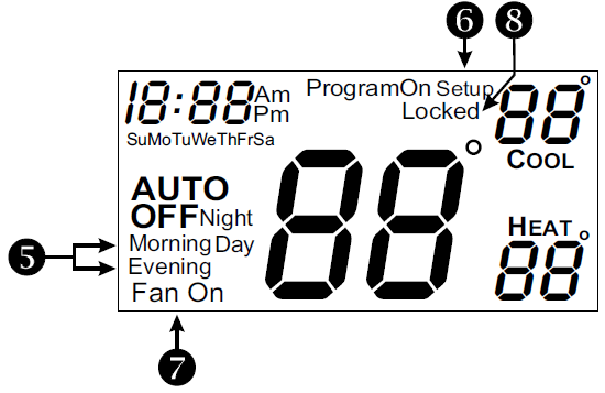
Display

- Mode Indicators
- Selects the operational mode of the equipment.
- HEAT: Indicates the heating mode.
- COOL: Indicates the air conditioning mode.
- AUTO: Indicates the system will automatically changeover between heat and cool modes as the temperature varies.
- PROGRAM ON: Indicates the time period program is enabled to run.
- OFF: Indicates heating and cooling are turned off.
- Selects the operational mode of the equipment.
- Clock with Day of the Week
- Indicates the current time and day. This clock is also used to program the time period schedules.
- Room Temperature Display
- Indicates current room temperature.
- Desired Set Temperature
- Indicates desired room temperature(s).
- Indicates desired room temperature(s).
- Morning, Day, Evening & Night icons
- Indicates the day part of the time period program.
- Setup icon
- Indicates the thermostat is in the setup mode.
- Fan On icon
- Indicates constant, continuous fan operation.
- When Fan On is not lit – indicates the fan will only operate when necessary to heat or to cool.
- Locked icon
- This indicates the keypad has been locked.
Quick Start
Set the Clock and Go

- Press the MODE button.
- While holding MODE, press the FAN button for two seconds to enter Setup screens.
During Setup & Programming
- Pressing the UP or DOWN button will modify the flashing selection.
Setting the Clock/ Setting the Day

 To adjust the Clock or Day use buttons.
The thermostat is preprogrammed from the factory to operate one or two stage equipment* without the need for further programming. To optimize the installation of this thermostat, follow the instructions in the Advanced Setup section.
The thermostat is not preprogrammed from the factory to operate electric heat or heat pump systems. To control these systems, follow the instructions in the Receiver manual.
Selecting the Heat or Cool Mode
Select Mode by Pressing the MODE Button

Basic Operation
Selecting Your Desired Temperature (adjusting the setpoints)
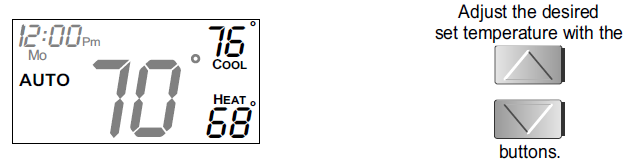
AUTO OR PROGRAM MODE
- Pressing the UP or DOWN button in Auto or Program mode will adjust both the heat and cool set temperatures simultaneously.
HEAT OR COOL MODE
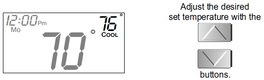
- Pressing the UP or DOWN button in Heat or Cool mode will adjust only the heat or cool set temperature.
Using the Fan Button
 Press
Press
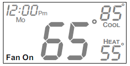
- Fan On indicates constant fan operation. You may turn the fan on even if the thermostat is in the Off mode. Pressing the FAN button toggles this feature on or off.
Programming a Daily Schedule
 Press the MODE button. While holding MODE, press the UP button for two seconds to enter time period programming*.
Use the Programming Worksheet on the back cover to help with this section.
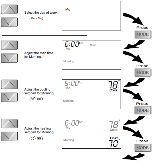
- Time period programming is only available on Unit Number 1.
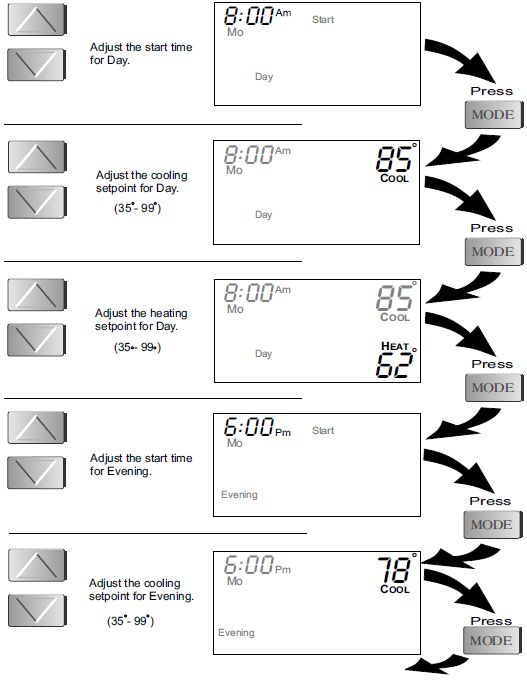
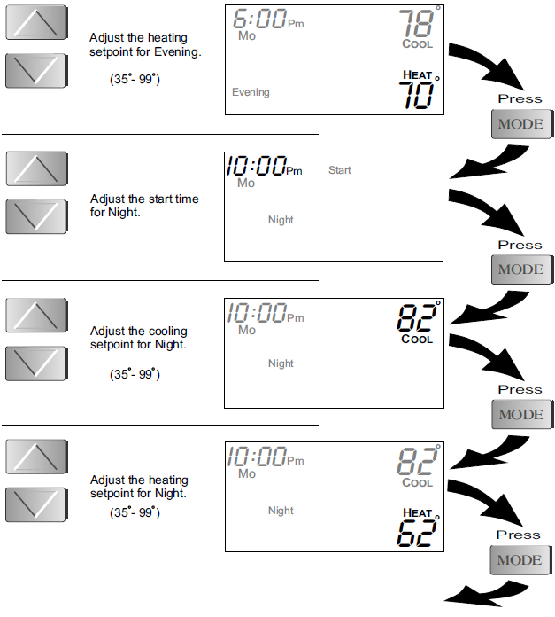
- The copy command becomes available after programming the entire previous day.
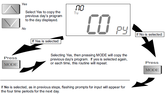
After programming for all seven days is complete, press the MODE and UP buttons at the same time for two seconds to leave the Setup screens. If no buttons are pressed, the display will leave the setup screens after 30 seconds.
Advanced Setup
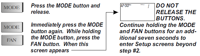
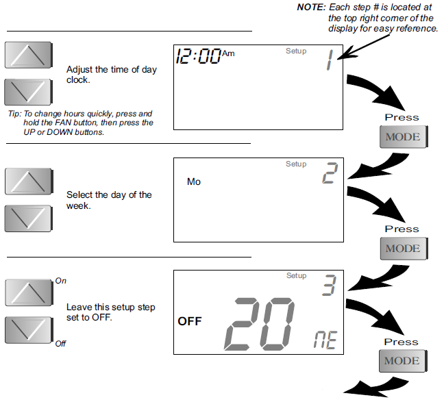

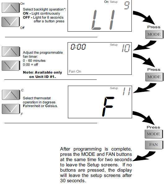
- For increased battery life the backlight should be set to OFF unless the P474-0800 RF power supply adaptor is used to power the thermostat.
Advanced Setup Table
| Step # | Description | Range | Factory Default |
| 1 | Time of Day | 24 hour | 12:00 am |
| 2 | Day of the Week | Mo – Su | Mo |
| 3* | Zoning System | Off / On | Off |
| 4 | House Code | 0 – 63 | 0 |
| 5 | Unit ID Number | 1 – 4 | 1 |
| 6** | Deadband/Temp. Swing 1st Stage | 1 – 6 | 2 |
| 7 | Minimum Heat/Cool Differential | 0 – 6 | 2 |
| 8** | Cycles Per Hour | d, d1, 2 – 6 | 6 |
| 9*** | Thermoglow Backlight | 0:00 – 0:60 | 0:00 |
| 10** | Programmable Fan | Off / On | On |
| 11 | Fahrenheit or Celsius | F / C | F |
- For proper operation this setup step should remain in the off position.
- These setup steps are only available on the thermostat programmed as Unit ID Number 1.
- For increased battery life the backlight should be set to OFF unless the P474-0800 RF power supply adaptor is used to power the thermostat.
About Advanced Features & Operation
CALIBRATION
Under normal circumstances, it will not be necessary to adjust the calibration of the temperature sensor. If calibration is required, please contact a trained HVAC technician to correctly perform the following procedure.
 Press
Press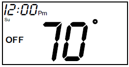
- Place the thermostat in the OFF mode.
 Press
Press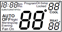
- Press and hold the MODE button.
- While holding the MODE button, press and hold the DOWN button for 5 seconds. All of the icons will appear on the display.
 Press
Press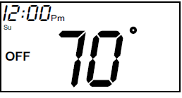
- Press the MODE button at the same time twice. The thermostat temperature will be displayed and may be calibrated using the UP or DOWN buttons
- Press
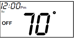
- After calibration is complete, press the MODE button once to save your changes and return to normal operation.
DEADBAND OPERATION
Controls up to two Heat and two Cool stages (please see the diagram below).
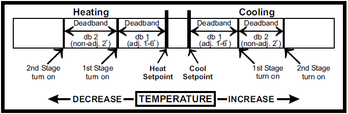
The 1st Stage of heat or cool is turned on when
- The temperature spread from the setpoint is equal to or greater than: the setpoint plus the 1st stage deadband (step #6). This 1st stage deadband is adjustable from 1-6 degrees and the default is two degrees.
The 2nd Stage of heat or cool is turned on when: (A) The 1st Stage has been on for a minimum of two minutes.
- The temperature spread from the setpoint is equal to or greater than the setpoint plus the 1st stage deadband (step #6), plus the 2nd stage deadband. This 2nd stage deadband is fixed at two degrees and is not adjustable.
FACTORY DEFAULTS
- If, for any reason, you desire to return all the stored settings back to the factory default settings, follow the instructions below.
WARNING: This will reset all Time Period and Advanced Programming to the default settings. Any information entered prior to this reset will be permanently lost.
- Press
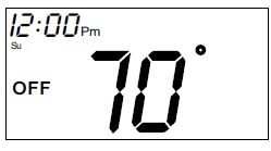
- Place the thermostat in the OFF mode.
- Press
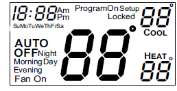
- Press and hold the MODE button.
- While holding the MODE button, press and hold the DOWN button for 5 seconds. All of the icons will appear on the display.
- Press
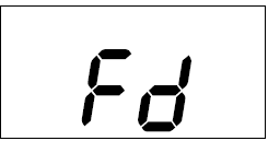
- After all of the icons appear, release the MODE and DOWN buttons. Then press and hold the FAN button for 5 seconds.
- Press
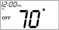
- After the letters Fd appear on the display (Factory Default), release the FAN button. Press the MODE button twice to return to normal operation.
HEAT/COOL DIFFERENTIAL
The Heat and Cool setpoints will not be allowed to come any closer to each other than the value set in Advanced Setup step #7,. This minimum difference is enforced during Auto-changeover operation. and Program On
Note: To increase the spread between the heating and cooling setpoints, press the MODE button until only the heat setpoint is displayed; adjust to the desired setpoint. Press the MODE button until only the cool setpoint is displayed; adjust to the desired setpoint. Press the MODE button again to enter the Auto-changeover mode where both the heat and cool setpoints are displayed.
MEMORY BACKUP
- In the event of a power loss, the thermostat will retain the stored program settings without external power or batteries.
PROGRAMMABLE FAN
- This timer will start the fan at the top of each hour; and the fan will run for the number of minutes selected in step #10.
KEYPAD LOCKOUT
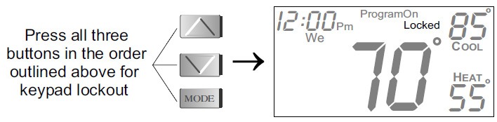
- To prevent unauthorized use of the thermostat, the front panel buttons may be disabled. To disable, or ‘lock’ the keypad, press and hold the MODE button. While holding the MODE button, press the UP and DOWN buttons together. The LOCKED icon will appear on the display, then release the buttons.
To unlock the keypad, press and hold the MODE button. While holding the MODE button, press the UP and DOWN buttons together. The LOCKED icon will disappear from the display, then release the buttons.
BATTERY ELIMINATOR (optional accessory)
The P474-0800 RF power supply adaptor is used to power the thermostat and eliminate the need for replacing batteries each year. Use only the Totaline accessory P474-0800 for proper operation.
LOW BATTERY WARNING
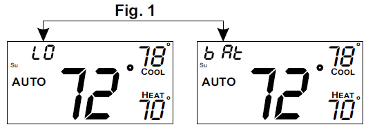
The two AA lithium batteries must be replaced at least once every 12 months to ensure proper operation. The “low battery” icon (fig. 1) will appear on the display when it is time to replace the batteries. When the “low battery” icon is displayed the batteries must be replaced immediately. The manufacturer cannot be liable for improper operation of the thermostat if the batteries are not immediately replaced. Annual battery replacement is especially critical in locations subject to freezing temperatures. The thermostat will be unable to turn on the heating system if the batteries are exhausted.
Important: To assure proper operation use only AA LITHIUM batteries.
Warranty
Five-Year Warranty
This Product is warranted to be free from defects in material and workmanship. If it appears within five year from the date of original installation, whether or not actual use begins on that date, that the product does not meet this warranty, a new or remanufactured part, at the manufacturer’s sole option to replace any defective part, will be provided without charge for the part itself provided the defective part is returned to the distributor through a qualified servicing dealer.
THIS WARRANTY DOES NOT INCLUDE LABOR OR OTHER COSTS incurred for diagnosing, repairing, removing, installing, shipping, servicing or handling of either defective parts or replacement parts. Such costs may be covered by a separate warranty provided by the installer. THIS WARRANTY APPLIES ONLY TO PRODUCTS IN THEIR ORIGINAL INSTALLATION LOCATION AND BECOMES VOID UPON REINSTALLATION.
LIMITATIONS OF WARRANTIES
ALL IMPLIED WARRANTIES (INCLUDING IMPLIED WARRANTIES OF FITNESS FOR A PARTICULAR PURPOSE AND MERCHANTABILITY) ARE HEREBY LIMITED IN DURATION TO THE PERIOD FOR WHICH THE LIMITED WARRANTY IS GIVEN. SOME STATES DO NOT ALLOW LIMITATIONS ON HOW LONG AN IMPLIED WARRANTY LASTS, SO THE ABOVE MAY NOT APPLY TO YOU. THE EXPRESSED WARRANTIES MADE IN THIS WARRANTY ARE EXCLUSIVE AND MAY NOT BE ALTERED, ENLARGED, OR CHANGED BY ANY DISTRIBUTOR, DEALER, OR OTHER PERSON WHATSOEVER. ALL WORK UNDER THE TERMS OF THIS WARRANTY SHALL BE PERFORMED DURING NORMAL WORKING HOURS. ALL REPLACEMENT PARTS, WHETHER NEW OR REMANUFACTURED, ASSUME AS THEIR WARRANTY PERIOD ONLY THE REMAINING TIME PERIOD OF THIS WARRANTY.
THE MANUFACTURER WILL NOT BE RESPONSIBLE FOR
- Normal maintenance as outlined in the installation and servicing instructions or owner’s manual, including filter cleaning and/or replacement and lubrication.
- Damage or repairs required as a consequence of faulty installation, misapplication, abuse, improper servicing, unauthorized alteration or improper operation.
- Failure to start due to voltage conditions, blown fuses, open circuit breakers or other damages due to the inadequacy or interruption of electrical service.
- Damage as a result of floods, winds, fires, lightning, accidents, corrosive environments or other conditions beyond the control of the Manufacturer.
- Parts not supplied or designated by the Manufacturer, or damages resulting from their use.
- Manufacturer products installed outside the continental U.S.A., Alaska, Hawaii, and Canada.
- Electricity or fuel costs or increases in electricity or fuel costs for any reason whatsoever including additional or unusual use of supplemental electric heat.
- ANY SPECIAL INDIRECT OR CONSEQUENTIAL PROPERTY OR COMMERCIAL DAMAGE OF ANY NATURE WHATSOEVER. Some states do not allow the exclusion of incidental or consequential damages, so the above may not apply to you.
This warranty gives you specific legal rights and you may also have other rights which may vary from state to state.
Programming Worksheet
| DAY | PERIOD | START TIME | COOL | HEAT | ||
|
MON DAY |
Morning | |||||
| Day | ||||||
| Evening | ||||||
| Night | ||||||
| TUESDAY | Morning | Copy Mon Tue | ||||
| Day | No Yes | |||||
| Evening | ||||||
| Night | ||||||
| WEDNESDAY | Morning | Copy Tue Wed | ||||
| Day | No Yes | |||||
| Evening | ||||||
| Night | ||||||
| THURSDAY | Morning | Copy Wed Thu | ||||
| Day | No Yes | |||||
| Evening | ||||||
| Night | ||||||
|
FRIDAY |
Morning | Copy Thu Fri | ||||
| Day | No Yes | |||||
| Evening | ||||||
| Night | ||||||
| SATURDAY | Morning | Copy Fri Sat | ||||
| Day | No Yes | |||||
| Evening | ||||||
| Night | ||||||
|
SUNDAY |
Morning | Copy Sat Sun | ||||
| Day | No Yes | |||||
| Evening | ||||||
| Night | ||||||
 Printed on recycled paper.
P/N 88-209 Rev. 2
Form: OG-P474-08
Catalog: 53P4-747
Replacement Components ©Division Carrier Corporation 03/07
Reference
Download Manual:
Totaline P474-1100RF Programmable Digital Thermostat Owners MANUAL
Totaline P474-1100RF Programmable Digital Thermostat Owners MANUAL