
Tekmar IOM-T-560 Programmable Thermostat
Compatible With
- 1-stage heating
- Supports optional floor sensors for radiant floor heating applications
Important Safety Information
It is your responsibility to ensure that this thermostat is safely installed according to all applicable codes and standards. tekmar is not responsible for damages resulting from improper installation and/or maintenance.
![]() This is a safety alert symbol. The safety alert symbol is shown alone or used with a signal word (DANGER, WARNING, or CAUTION), a pictorial, and/or a safety message to identify hazards.
This is a safety alert symbol. The safety alert symbol is shown alone or used with a signal word (DANGER, WARNING, or CAUTION), a pictorial, and/or a safety message to identify hazards.
 When you see this symbol alone or with a signal word on your equipment or in this Manual, be alert to the potential for death or serious personal injury.
![]() This pictorial alerts you to electricity, electrocution, and shock hazards.
This pictorial alerts you to electricity, electrocution, and shock hazards.
![]() This symbol identifies hazards that, if not avoided, could result in death or serious injury.
This symbol identifies hazards that, if not avoided, could result in death or serious injury.
![]() This symbol identifies hazards that, if not avoided, could result in minor or moderate injury.
This symbol identifies hazards that, if not avoided, could result in minor or moderate injury.
This symbol identifies practices, actions, or failure to act which could result in property damage or damage to the equipment.
![]() Read the Manual and all product labels BEFORE using the equipment. Do not use it unless you know the safe and proper operation of this equipment. Keep this Manual available for easy access by all users. Replacement Manuals are available at tekmarControls.com
Read the Manual and all product labels BEFORE using the equipment. Do not use it unless you know the safe and proper operation of this equipment. Keep this Manual available for easy access by all users. Replacement Manuals are available at tekmarControls.com
![]()
- It is the installer’s responsibility to ensure that this thermostat is safely installed according to all applicable codes and standards.
- Improper installation and operation of this thermostat could result in damage to the equipment and possibly even personal injury or death.
- This thermostat is not intended for use as a primary limit control. Other controls that are intended and certified as safety limits must be placed into the control circuit.
![]() Do not attempt to service the thermostat. There are no user-serviceable parts inside the thermostat. Attempting to do so voids the warranty.
Do not attempt to service the thermostat. There are no user-serviceable parts inside the thermostat. Attempting to do so voids the warranty.
Installation
Preparation
Tools Required
- tekmar or jeweler screwdriver
- Phillips head screwdriver
- Wire stripper
- Drill (for wall anchor)
- 3/16″ drill bit (for wall anchor)
Materials Required
- 18 AWG LVT Solid Wire (Low Voltage Connections)
Installation Location
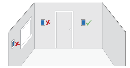
 Consider the following:
- Interior Wall.
- Keep dry. Avoid potential leakage onto the control.
- Relative Humidity less than 90%. Non-condensing environment.
- No exposure to extreme temperatures beyond 32-122°F (0-50°C).
- No draft, direct sun, or other cause for inaccurate temperature readings.
- Away from equipment, appliances, or other sources of electrical interference.
- Easy access for wiring, viewing, and adjusting the display screen.
- Approximately 5 feet (1.5 m) off the finished floor.
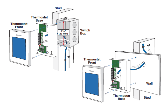
- The maximum length of the wire is 500 feet (150 m).
- Strip wire to 3/8″ (10 mm) for all terminal connections.
- Use standard 8 conductors and 18 AWG wires.
Removing The Thermostat Base
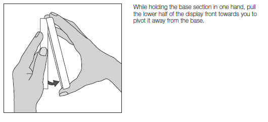
Moving The Thermostat
To prevent the risk of personal injury and/or death, make sure power is not applied to the thermostat until it is fully installed and ready for final testing. All work must be done with power to the circuit being worked on turned off. Please be aware local codes may require this thermostat to be installed or connected by an electrician.
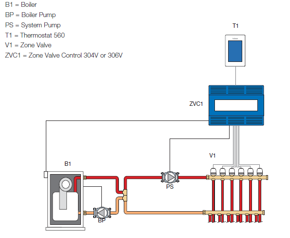
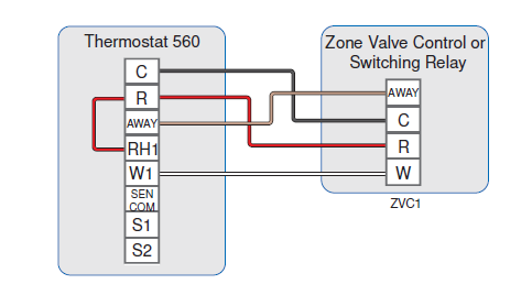
Application 560-1
The Thermostat 560 operates a radiant floor heating system. The thermostat uses a built-in air temperature sensor.
Mechanical
Legend
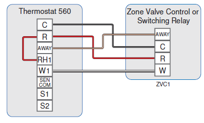
Electrical
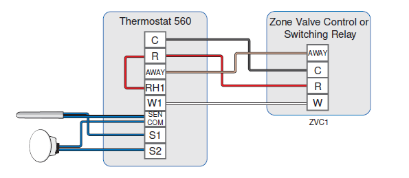
Application 560-2
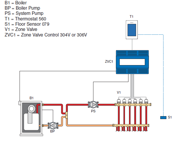
The Thermostat 560 operates a radiant floor heating system based on the floor temperature sensor. The built-in air sensor is disabled.
Mechanical
Electrical

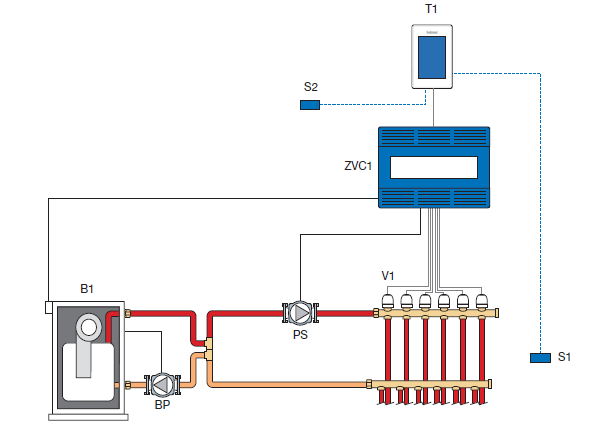
Mechanical
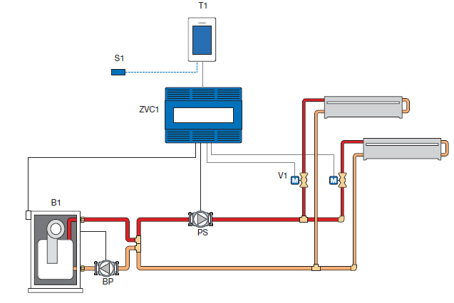
The Thermostat 560 operates a radiant floor heating system. The thermostat uses both air and floor temperature sensors. The air temperature sensor can be either built-in and/or external.
Legend
- B1 = Boiler
- BP = Boiler Pump
- PS = System Pump T
- 1 = Thermostat 560
- S1 = Floor Sensor 079
- S2 = Optional
- Indoor Sensor 084
- V1 = Zone Valve
- ZVC1 = Zone Valve
- Control 304V or 306V
Electrical
Mechanical
The Thermostat 560 operates a baseboard/radiator using an air temperature sensor. The air temperature sensor can be either built-in and/or external.
Legend
- B1 = Boiler
- BP = Boiler Pump
- PS = System Pump
- T1 = Thermostat 560
- S1 = Optional Indoor Sensor 084
- V1 = Zone Valve
- ZVC1 = Zone Valve Control 304V or 306V
Electrical
Sequence of Operation
Heating Operation
The Heat On symbol is shown on the display when the thermostat is heating. Heating for freeze protection is provided whenever the air or floor temperature falls below 40°F (4.5°C), regardless of operating mode.
Regular Heating
W1 relay is on when the air temperature falls 1.5°F (1°C) below the Heat To setting. When the temperature reaches the Heat To setting, the relay turns off.
Radiant Floor Heating
When Radiant Floor Heating is selected in the setup menu, the W1 relay operates using Pulse Width Modulation. This improves comfort for radiant systems with high-mass floors.
- 100% on time at Heat To setting -1.5°F
- 50% on time at Heat To setting
- 0% on time at Heat To setting + 1.5°F
Room Sensor and Averaging
The room temperature can be measured using a combination of built-in and auxiliary sensors.
- Built-in room sensor only
- Built-in room sensor with auxiliary room sensor(s) (temperature is averaged)
- Auxiliary room sensor only
Floor Sensor for Radiant Floor Heating
If a floor sensor is connected, floor minimum and maximum settings are available. For a combination of air and floor temperature control, leave the internal air sensor on in the setup menu. A floor minimum can be used to prevent a fast drop in temperature caused by receding solar exposure. This operation is recommended for areas heated by afternoon sun through large windows. When the sun sets, it can take a long time for the floors to get warm again. This may cause the room to cool off too much in the early evening. A floor minimum setting can help with this condition by maintaining a floor minimum temperature. Keep in mind the floor minimum temperature will override the air temperature, and if set too high, may overheat the room. A floor maximum is recommended for rooms with hardwood floors. Setting floor minimum and
maximum temperatures is a way of enhancing the comfort of the living space while protecting the floor coverings. If there is more than one-floor temperature sensor, the temperature is averaged.
Warm Weather Shut Down (WWSD)
The heating system can automatically shut off based on the outdoor temperature and the WWSD setting. This provides a convenient way to shut off radiant floor heating. The WWSD feature requires the installation of an Outdoor Sensor 070.
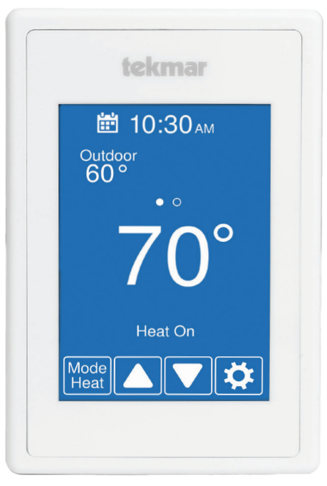
User Interface
After 60 seconds of inactivity, the thermostat home screen displays only the time and the temperature.
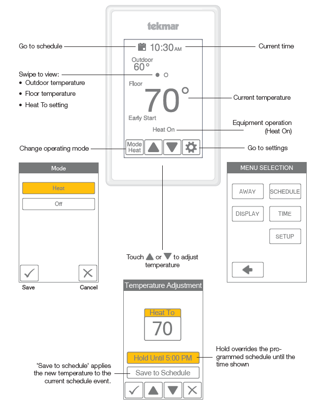
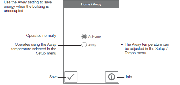
Away
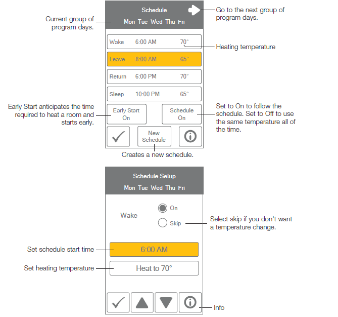
Schedule
Display
| Setting | Range | Default |
| Temperature units
Select °F or °C. |
°F or °C |
°F |
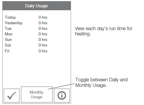
| ENERGY USE
View the number of hours the heating or cooling has operated either daily or monthly. |
0 to 24 (daily) 0 to 744 (monthly) |
0 hours |
| Setting | Range | Default |
| BRIGHTNESS ACTIVE
Select the brightness when touching the screen. |
30 to 100% |
100% |
| BRIGHTNESS INACTIVE
Select the brightness when not in use. |
Off, 30 to 100% |
50% |
|
BACKGROUND Select the background color. |
Light, Blue, Night, Latte, Espresso |
Blue |
|
LANGUAGE Select the language. |
English, Español, Français |
English |
| SCREEN CLEAN
Locks the screen for 10 seconds to allow cleaning. |
N/A |
N/A |
| INACTIVE TIME DISPLAY
Select if the time is visible when the display is inactive. |
Off or On |
On |
| INACTIVE OUTDOOR DISPLAY
Select if the outdoor temperature is visible when the display is inactive. Requires an Outdoor Sensor 070. |
Off or On |
Off |
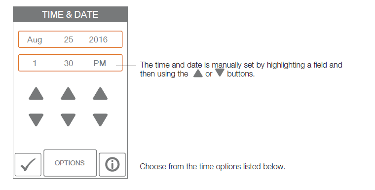
Time
| Setting | Range | Default |
| TIME FORMAT
Select the time format. |
12 or 24 hour | 12 hour |
| DAYLIGHT SAVING TIME
Select the brightness when not in use. |
Off, On | On |
Installer Settings
Setup
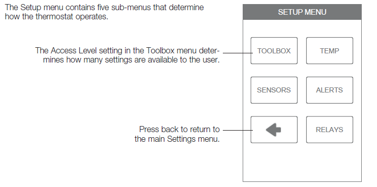
The Setup menu contains five sub-menus that determine how the thermostat operates.
Setup – Toolbox
| Setting | Range | Default |
| ERROR
Displays any error messages. |
N/A |
N/A |
| ACCESS LEVEL
Select between user and installer access levels. User access level restricts access in the Setup Menu. |
User, Installer |
Installer |
| STATUS
The current status of warm weather shut down, cold weather shut down, and each of the relays. |
WWSD, W1 |
N/A |
| SOFTWARE VERSION
Display the software version. |
J1302-1.0.0 |
N/A |
| LOAD DEFAULTS
All settings are returned to factory defaults. |
Yes, No |
No |
| CALIBRATE TOUCHSCREEN
Recalibrate the screen after loading factory defaults. |
N/A |
N/A |
| Setting | Range | Default |
| Screen Page 1 | ||
| FLOOR MIN
Select the floor temperature minimum. This applies when there is both floor and air sensors and when no schedule is set. |
Off, 40 to 95°F Off, 4.5 to 35.0°C |
Off |
| FLOOR MIN – WAKE
Select the floor temperature while in the wake schedule. This applies when there is both a floor and an air sensor. |
Off, 40 to 95°F Off, 4.5 to 35.0°C |
Off |
| FLOOR MIN – LEAVE
Select the floor temperature while in the leave schedule. This applies when there is both a floor and an air sensor. |
Off, 40 to 95°F Off, 4.5 to 35.0°C |
Off |
| FLOOR MIN – RETURN
Select the floor temperature while in the return schedule. This applies when there is both a floor and an air sensor. |
Off, 40 to 95°F Off, 4.5 to 35.0°C |
Off |
| FLOOR MIN – SLEEP
Select the floor temperature while in the sleep schedule. This applies when there is both a floor and an air sensor. |
Off, 40 to 95°F Off, 4.5 to 35.0°C |
Off |
| FLOOR MIN – AWAY
Select the floor temperature while in a away Applies when there is both a floor and an air sensor. |
Off, 40 to 95°F Off, 4.5 to 35.0°C |
Off |
| Screen Page 2 | ||
| FLOOR MAX
Select the maximum floor temperature. This protects the floor covering from overheating. This applies when there is a floor sensor. |
Off, 40 to 95°F Off, 4.5 to 35.0°C |
Off |
| HEAT TO AWAY
Select the heating temperature when away. |
Off, 40 to 95°F
Off, 4.5 to 35.0°C |
62°F
(16.5°C) |
| HEAT TO MIN LIMIT
Select the minimum heating temperature limit. |
Off, 40 to 95°F
Off, 4.5 to 35.0°C |
Off |
| HEAT TO MAX LIMIT
Select the maximum heating temperature limit. |
Off, 40 to 95°F
Off, 4.5 to 35.0°C |
Off |
| WARM WEATHER SHUT DOWN
Select the outdoor temperature at which the heating is shut off. The WWSD feature requires an Outdoor Sensor 070. |
Off, 40 to 95°F Off, 4.5 to 35.0°C |
Off |
| Setup – Sensors | ||
| Setting | Range | Default |
| SENSOR 1
Select the type of sensor connected to S1 and Com wiring terminals. |
Off, Room, Floor |
Off |
| SENSOR 2
Select the type of sensor connected to S2 and Com wiring terminals. |
Off, Room, Floor, Outdoor |
Off |
| INTERNAL ROOM SENSOR
Select if the internal room temperature sensor is on or off. Only available when Sensor 1 or 2 is set to read a room or floor sensor. |
Off, On |
On |
| ROOM OFFSET
Select if the internal room temperature sensor is on or off. Only available when Sensor 1 or 2 is set to read a room or floor sensor. |
Off, -5 to +5°F -3.0 to 3.0°C |
Off |
|
FLOOR OFFSET Manual offset correction of the floor temperature measurement. |
Off,
-5 to +5°F -3.0 to 3.0°C |
Off |
| Setup – Alerts | ||
| Setting | Range | Default |
| ROOM HOT WARNING
Displays error on the home screen if the room exceeds this temperature. |
Off, 40 to 100°F Off, 4.5 to 38.0°C |
Off |
| ROOM COLD WARNING
Displays error on the home screen if the room falls below this temperature. |
Off, 40 to 100°F Off, 4.5 to 38.0°C |
Off |
| Setup – Relays | ||
| Setting | Range | Default |
| RADIANT FLOOR HEATING
Select if the first stage W1 heats a radiant floor. |
No, Yes |
No |
Error Messages
An error icon will appear on the home screen when an error is present.
| Description |
| MEMORY ERROR
The thermostat memory settings are corrupted. To clear, load the factory defaults in the Toolbox menu. The thermostat will not operate any heating equipment while this error message is present. |
| INTERNAL ROOM SENSOR FAULT
Due to an open or short circuit, the thermostat is unable to read the internal room temperature sensor. If sensor 1 or 2 is set to room the thermostat continues to operate, otherwise operation stops. The error cannot be field repaired. Contact your tekmar sales representative for warranty or repair procedures. |
| SENSOR 1 FAULT
Due to an open or short circuit, the thermostat is unable to read the sensor wired to S1 and Com. The thermostat stops normal operation if sensor 1 is the only active room or floor sensor or if a floor maximum temperature has been set. Check the auxiliary sensor wire for short circuits according to the sensor installation manual. It may be necessary to replace the auxiliary sensor. Once the error has been corrected, the error message automatically clears. |
| SENSOR 2 FAULT
Due to an open or short circuit, the thermostat is unable to read the sensor wired to S2 and Com. The thermostat stops normal operation if sensor 2 is the only active room or floor sensor or if a floor maximum temperature has been set. Check the auxiliary sensor wire for short circuits according to the sensor installation manual. It may be necessary to replace the auxiliary sensor. Once the error has been corrected, the error message automatically clears. |
| ROOM HOT WARNING
The room temperature is above the Room Hot Warning setting in the Alerts menu. The warning will automatically clear once the room temperature falls below the setting. |
| ROOM COLD WARNING
The room temperature is below the Room Cold Warning setting in the Alerts menu. The warning will automatically clear once the room temperature rises above the setting. |
Technical Data
| THERMOSTAT 560 ONE-STAGE HEAT | |
| Literature | ES-T-560, IOM-T-560, 560_J, UserManual-T-560 |
| Control | Microprocessor control. This is not a safety (limit) control. |
| Packaged weight | 0.6 lb. (270 g) |
| Dimensions | 4-5/8″ H x 3″ W x 15/16″ D (118 x 76 x 24 mm) |
| Enclosure | White PVC plastic, NEMA Type 1 |
| Approvals | Meets Class B: ICES & FCC Part 15 |
| Ambient conditions | Indoor use only, 32 to 122°F (0 to 50°C), RH ≤90% non-condensing |
| Power supply | 15 to 30 V (ac/dc), 2 VA standby, Class 2 |
| Relays | 30 V (ac/dc), 2 A, Class 2 circuits |
| Sensor | NTC thermistor, 10 kΩ @ 77°F (25°C ±0.2°C) ß=3892 |
| – Included | None |
| – Optional | tekmar type # 070, 072, 073, 076, 077, 079, 084 |
Warranty
Limited Warranty The liability of tekmar under this warranty is limited. The Purchaser, by taking receipt of any tekmar product (“Product”), acknowledges the terms of the Limited Warranty in effect at the time of such Product sale and acknowledges that it has read and understands same. The tekmar Limited Warranty to the Purchaser on the Products sold hereunder is a manufacturer’s pass-through warranty which the Purchaser is authorized to pass through to its customers. Under the Limited Warranty, each tekmar Product is warranted against defects in workmanship and materials if the Product is installed and used in compliance with tekmar’s instructions, ordinary wear and tear excepted. The pass-through warranty period is for a period of twenty-four (24) months from the production date if the Product is not installed during that period, or twelve (12) months from the documented date of installation if installed within twenty-four (24) months from the production date.
The liability of tekmar under the Limited Warranty shall be limited to, at tekmar’s sole discretion: the cost of parts and labor provided by tekmar to repair defects in materials and/or workmanship of the defective product; or to the exchange of the defective product for a warranty replacement product; or to the granting of credit limited to the original cost of the defective product, and such repair, exchange or credit shall be the sole remedy available from tekmar, and, without limiting the foregoing in any way, tekmar is not responsible, in contract, tort or strict product liability, for any other losses, costs, expenses, inconveniences, or damages, whether direct, indirect, special, secondary, incidental or consequential, arising from ownership or use of the product, or from defects in workmanship or materials, including any liability for fundamental breach of contract. The pass-through Limited Warranty applies only to those defective Products returned to tekmar during the warranty period. This Limited Warranty does not cover the cost of the parts or labor to remove or transport the defective Product, or to reinstall the repaired or replacement Product, all such costs and expenses being subject to Purchaser’s agreement and warranty with its customers.
Any representations or warranties about the Products made by Purchaser to its customers which are different from or in excess of the tekmar Limited Warranty are the Purchaser’s sole responsibility and obligation. Purchaser shall indemnify and hold tekmar harmless from and against any and all claims, liabilities and damages of any kind or nature which arise out of or are related to any such representations or = warranties by Purchaser to its customers. The pass-through Limited Warranty does not apply if the returned Product has been damaged by negligence by persons other than tekmar, accident, fire, Act of God, abuse or misuse; or has been damaged by modifications alterations or attachments made subsequent to purchase which have not been authorized by tekmar; or if the Product was not installed in compliance with tekmar’s instructions and/or the local codes and ordinances; or if due to defective installation of the Product; or if the Product was not used in compliance with tekmar’s instructions.
THIS WARRANTY IS IN LIEU OF ALL OTHER WARRANTIES, EXPRESS OR IMPLIED, WHICH THE GOVERNING LAW ALLOWS PARTIES TO CONTRACTUALLY EXCLUDE, INCLUDING, WITHOUT LIMITATION, IMPLIED WARRANTIES OF MERCHANTABILITY AND FITNESS FOR A PARTICULAR PURPOSE, DURABILITY OR DESCRIPTION OF THE PRODUCT, ITS NON-INFRINGEMENT OF ANY RELEVANT PATENTS OR TRADEMARKS, AND ITS COMPLIANCE WITH OR NON-VIOLATION OF ANY APPLICABLE ENVIRONMENTAL, HEALTH OR SAFETY LEGISLATION; THE TERM OF ANY OTHER WARRANTY NOT HEREBY CONTRACTUALLY EXCLUDED IS LIMITED SUCH THAT IT SHALL NOT EXTEND BEYOND TWENTY-FOUR (24) MONTHS FROM THE PRODUCTION DATE TO THE EXTENT THAT SUCH LIMITATION IS ALLOWED BY THE GOVERNING LAW.
Product Warranty Return Procedure All Products that are believed to have defects in workmanship or materials must be returned, together with a written description of the defect, to the tekmar Representative assigned to the territory in which such Product is located. If tekmar receives an inquiry from someone other than a tekmar Representative, including an inquiry from Purchaser (if not a tekmar Representative) or Purchaser’s customers, regarding a potential warranty claim, tekmar’s sole obligation shall be to provide the address and other contact information regarding the appropriate Representative.
Need help? Go to our website or contact us.
watts.com/tekmar
[email protected]
1-800-438-3903
Reference:
Download manuals:
Tekmar IOM-T-560 programmable Thermostat Installational Manual
![]()
Tekmar IOM-T-560 programmable Thermostat Installational Manual
Leave a Reply