
SunStat 500675 Non-programmable Thermostat

Owner’s Manual
Your new SunStat Nonprogrammable thermostat is designed to control the voltage to either a 120VAC or 240VAC resistive floor warming system. Please follow this manual for complete installation and operation instructions. If you have any questions or comments, try calling Technical Support at 1-800-276-2419.
CAUTION: Make sure you are qualified and are familiar with house wiring. This is a line voltage device that could cause serious injury or damage if improperly installed.
Preparation
- Unpack your thermostat and make sure everything is in good condition: • Thermostat • Floor sensor • Small screwdriver • Mounting screws • Wire nuts for wiring connections
- If any parts are missing or damaged, contact the store where you purchased this thermostat. Do not install a damaged part.
- Gather the following tools and supplies:
- Phillips screwdriver, hole saw
- Wire strippers, “fish tape”, other electrical tools
- Electrical box for thermostat:
- If you are connecting to power leads from only 1 or 2 floor warming systems, you may use a single-gang, 31⁄2 inch deep box.
- If you are connecting to power leads from 3 floor warming systems, use a 4x4x21⁄8 inch or deeper box (not a 2-gang box) when your wall studs are still exposed. Install a single-gang “mud-ring” cover on the box before installing drywall materials.
- For more than 3 floor warming systems or other layouts, you may need to install a junction box to connect the power leads together. Then use house wire to connect between the junction box and the thermostat electrical box. See the installation instructions for your floor warming system for more information.
Installation
Remove the Thermostat Face
- Remove the thermostat Front Module from the Power Module by opening the door and loosening the screw.
- Pull outward near the bottom on the Front Module and lift off. Be careful not to bend or damage the 14-pin electrical connector on the back of the Front Module.

Prepare the Wiring
- Find a location for your thermostat. It is suitable for indoor use only, on insulated or uninsulated walls. Locate it about 41⁄2 feet to 5 feet above the floor on an inside wall. Make sure it is well ventilated and not located in a confined space such as a small closet or cabinet. Avoid placing it near other heat sources such as hot-water piping, heat duct, wall-mount lighting, and direct sunlight to help prevent adversely affecting the thermostat.
- Turn off the power to the floor warming system at the main circuit panel before doing any electrical work.
- A qualified electrician should run a dedicated circuit from the main circuit panel to the thermostat location.
- If a dedicated circuit is not possible, you may tap from another circuit in the room. Make sure there is enough load capacity (amps) to handle the addition of your floor warming system, and that it is NOT wired in series with any other device, including other GFCIs.
- The circuit breaker in the main circuit panel should be 15 amps maximum for a floor warming system totaling 12 amps or less. For larger systems up to 15 amps, use a 20 amp maximum circuit breaker. Never exceed 15 amps on this thermostat. You may consider using an arc-fault (AFCI) type circuit breaker for additional protection.
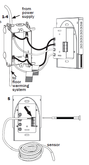
- Pull the power supply wiring into this box, leaving about 6 inches of wire.
- Pull the floor sensor wire and the power lead wires from your floor warming system up the wall, into this box. Refer to your floor warming system installation instructions for placement of the floor sensor tip into the floor area.
- Note: The sensor wires should not be run in the same conduit as line voltage wires to avoid possible interference. If the sensor lead wires are not long enough, they may be extended an additional 15 feet (4.5 m) using minimum 20-gage 2-conductor wire or up to 50 feet (15 m) using shielded wire.
- Mount the electrical box.
Connect Wires
- Match and connect the two wires marked “LINE1” and “LINE2” to the power supply wires using the wire nuts provided.
- Gently tug on the wires to make sure they are secure, otherwise a wire could loosen and cause failure.
- Overwrap the wire nuts with electrical tape to better secure them to the wires.
- Match and connect the two wires marked “LOAD1” and “LOAD2” to the floor warming system lead wires and secure these wires the same way.
- Connect the house ground wire to the green or bare lead wire(s) of your floor warming system.
- Insert the ends of the floor sensor wire into the “SENSOR” terminals (1 and 2) and tighten the screws. There is no polarity, so it does not matter which wire end goes into which terminal
Remote Control
- If you want to connect your thermostat to a remote control device, such as a home automation system, first make sure that the remote device has a “dry contact” output (an un-energized switch, such as the contacts on a relay).
- Many home automation systems come with such an output that opens or closes at specified times.
- Pull 2-conductor wire, size 18- to 24-gage, through the wall from the remote device, into this electrical box.
- Connect the wire ends into the “SETBACK” terminals (5 and 6) and tighten the screws (no polarity).
SunStat Relays
- If you want to use your thermostat to drive a SunStat Relay(s) (ask your dealer about this convenient way to control larger systems with one thermostat), first read and follow the instructions for the SunStat Relay thoroughly.
- Pull 2-conductor wire, size 18- to 24-gage, through the wall from the SunStat Relay, into this electrical box. This wire may be up to 100 feet (30 m) in length from the thermostat to the last SunStat Relay installed.
- Connect the wire ends into the “RELOUT” terminals (3 and 4) and tighten the screws (Observe polarity of the wires when connecting to the SunStat Relay).
Mount the Thermostat
- Carefully fold and press the wires back into the electrical box. Do not use the thermostat to push them in, as this may cause connections to loosen and possible failure.
- Secure the thermostat Power Module into the box with the mounting screws provided.
- Carefully snap the Front Module onto the Power Module. Be careful not to bend or damage the 14-pin electrical connector on the back of the Front Module.
- Tighten the screw.
- Switch on the power at the main circuit panel.
- NOTE to contractors: After installing the thermostat, be sure to:
- Do a Quick Setup (section 3),
- Temporarily override the setpoint temperature to make sure it is heating for a few minutes (section 5),
- Test the GFCI (section 5).
![Skip to main contentSkip to toolbar About WordPress thermostat.guide 11 update available 11 Comment in moderation New View Post Performance 1 View Post (AMP) Howdy, wpx_thermostats Log Out Screen OptionsHelp Edit Post Add New Post updated. View post Dismiss this notice. Add title SunStat 500675 Non-programmable Thermostat Owners Manual Permalink: https://thermostat.guide/sunstat/sunstat-500675-n…at-owners-manual/ Edit Add MediaAdd PDFVisualText Paragraph UL » LI Word count: 2658 Last edited by wpx_thermostats on March 10, 2023 at 9:32 am Move upMove downToggle panel: Yoast SEO Move upMove downToggle panel: Publish Preview Changes(opens in a new tab) Status: Published EditEdit status Visibility: Public EditEdit visibility Revisions: 4 BrowseBrowse revisions Published on: Mar 10, 2023 at 09:18 EditEdit date and time SEO: Not available Readability: Needs improvement Purge from cache Move to Trash Move upMove downToggle panel: Show AMP for Current Post? Move upMove downToggle panel: Featured image SunStat- 500675- Non-programmable -Thermostat -FEA Click the image to edit or update Remove featured image Move upMove downToggle panel: Tags Add New Tag Separate tags with commas Remove term: 500675 500675Remove term: 500675 Thermostat 500675 ThermostatRemove term: Non-Programmable Thermostat Non-Programmable ThermostatRemove term: Owner’s Manual Owner’s ManualRemove term: SUNSTAT SUNSTATRemove term: SunStat 500675 SunStat 500675 Choose from the most used tags Move upMove downToggle panel: Table of Contents The table of contents will be automatic added to this post. Customize Disable TOC Move upMove downToggle panel: Post Attributes Template Default template Move upMove downToggle panel: Categories All Categories Most Used SunStat 2GIG ABB Airtouch AIRXCEL Alarm.com American Standard Aprilaire ATAG Aube Azel Beok Bosch Braeburn Bryant Bryant Housewise CADET CARRIER Center Coleman ComfortNet Daikin Danfoss Doit DOMETIC Drayton Ecobee EcoFactor ECONET Emerson EMOS EPH Controls FAQ Flomasta Frost Sentry Fujitsu GE-CYNC Google Nest Greenlite Hive Honeywell Honeywell Home Honeywell AUBE Honeywell Home Honeywell PRO HORSTMANN Hunter ICM Controls Ideal Ideal Halo IEC ILiving KALOR TECH KETOTEK King King Electric Lennox levoit Lux Lux/Go Luxpro Maxx Air MITSUBISHI ELECTRIC Mysa Neomitis Nexia Nuheat Orbit OWON Peco Pro1 Pro1 Technologies Proselect PROSTATE QuietWarmth Robertshaw Salus Saswell Schluter Systems SCHNEIDER ELECTRIC Shelly SIEMENS Stelpro SUNTOUCH TCS Bays Controls Tekmar Thermosoft Thermostats Trane Uponor Venstar Verdant Vine Vive WarmlyYours Warmup Waterfurnace Worcester Worcester Bosch Wyze ZEN THERMOSTAT + Add New Category Move upMove downToggle panel: Custom AMP Editor Move upMove downToggle panel: AMP Page Builder Start the AMP Page Builder Move upMove downToggle panel: sameAs Move upMove downToggle panel: Schema Exclude Turn Schema OFF Tick this checkbox to turn off Schema output on this entry. Move upMove downToggle panel: Revisions wpx_thermostats, 5 seconds ago (March 10, 2023 @ 09:32:10) wpx_thermostats, 2 mins ago (March 10, 2023 @ 09:30:31) [Autosave] wpx_thermostats, 11 mins ago (March 10, 2023 @ 09:21:18) wpx_thermostats, 14 mins ago (March 10, 2023 @ 09:18:45) Move upMove downToggle panel: Comments Add Comment No comments yet. Thank you for creating with WordPress.Version 6.1.1 Close dialog Add media Actions Upload filesMedia Library Filter mediaFilter by type Uploaded to this post Filter by date All dates Search Media list Showing 9 of 8 media items ATTACHMENT DETAILS SunStat-500675-Non-programmable-Thermostat-3.png March 10, 2023 17 KB 299 by 232 pixels Edit Image Delete permanently Alt Text Learn how to describe the purpose of the image(opens in a new tab). Leave empty if the image is purely decorative.Title SunStat- 500675- Non-programmable -Thermostat -3 Caption Description File URL: https://thermostat.guide/wp-content/uploads/2023/03/SunStat-500675-Non-programmable-Thermostat-3.png Copy URL to clipboard ATTACHMENT DISPLAY SETTINGS Alignment Center Link To None Size Full Size – 299 × 232 Selected media actions 1 item selected Clear Insert into post](https://thermostat.guide/wp-content/uploads/2023/03/SunStat-500675-Non-programmable-Thermostat-3.png)
Quick Setup
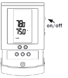
On/Off Switch
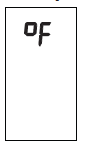
- Your thermostat should be turned off when it is first installed. The display will show OFF.
- Slide the on/off switch to the upper position, turning the thermostat on. The display will show the sensor temperature, setpoint temperature, and other information.
- To turn the thermostat off anytime, slide the on/off switch to the lower position. No heating will occur and all settings are retained.
 Change Format Between °F (Farenheit) and°C (Celsius)
- Your thermostat is factory set to operate in either °F format or °C format. If needed, you may change this at any time as follows:
- Press the OPTIONS button and hold for 1 second. An °F will show on the display.
- Press the down or up button to toggle °C.
- Press the HOLD/RETURN button to return to normal operating mode.
Additional Setups
Air Sensing and Regulator Modes
Your thermostat is factory set to operate based on the floor sensor temperature. This is the recommended method to properly control your floor warming system. However, it is also possible to operate your thermostat in either the air sensing mode or regulator mode temporarily if the floor sensor was damaged or not installed. A new floor sensor should be installed to enable operation in Floor Sense Mode as soon as possible. These modes must be used with caution to avoid overheating the floor.
- Air Sensing Mode – This operates by an air sensor inside the thermostat. You must set a Floor Limit temperature to avoid overheating the floor coverings (see Floor Limit below). Note: the internal heating in the thermostat may affect the sensor temperature.
- Regulator Mode– In this mode the user selects the amount of time the floor warming system heats during a 15-minute repeating cycle. There is no temperature sensing in this mode. (see section 5 “Operation”)
- If you want it to operate in the air sensing mode or regulator mode, you may change this as follows:
- Press the OPTIONS button and hold for 1 second.
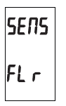
- Press the OPTIONS button again until SENS shows on the display.
- Press the down or up button to toggle this to Air or rEGu.
- Press the HOLD/RETURN button to return to the normal operating mode.
Floor Limit
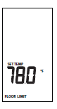
If you set your thermostat to operate in Air Sense Mode, the display will show the air temperature but will also monitor the floor sensor if it is connected. To avoid possibly overheating your floor, you must set a Floor Limit temperature so it turns off the system if the floor sensor temperature exceeds this Floor Limit. Some wood and laminate floor manufacturers recommend a maximum of 82 to 84°F (27° to 28°C). Check with the manufacturer. It is factory set to 99F (37C) and can be adjusted as follows:
- Press the OPTIONS button and hold for 1 second.
- Press the OPTIONS button again until SET TEMP and FLOOR
- LIMIT shows on the display with the current Floor Limit temperature.
- Press the down or up button to adjust this.
- Press the HOLD/RETURN button to return to normal operating mode.
Calibration
- Your thermostat allows the ability to slightly adjust the display temperature.
- Normally this is not recommended nor required. However, in special circumstances this may be necessary, and can be done as follows:
- Press the OPTIONS button and hold for 1 second.
- ress the OPTIONS button again until CAL shows on the display with the current sensor temperature and the current offset value.
- The offset value is factory set to zero.
- Press the down or up button to adjust this.
- Press the HOLD/RETURN button to return to normal operating mode.
Resetting Factory Defaults
- Your thermostat has the ability to reset all settings to the factory defaults. If you are certain you want to do this:
- Press the OPTIONS button and hold for 1 second.
- Press the OPTIONS button again until the software version Soft 1.0 or similar shows on the display.
- Press the down and up buttons at the same time and hold for 1 second. Done and rst will show on the display. The thermostat will go through a startup mode and return to the normal operating mode.
Operation
Controlling the Temperature
Your thermostat has several ways to control your floor warming system.
Adjust the Temperature
- Press the down or up button and hold for 1 second. The setpoint temperature should be blinking.
- Press the down or up button again to adjust the temperature.
- Press the HOLD/RETURN button or wait 5 seconds and the thermostat will return to normal operating mode, saving your adjustment.
Setback
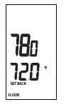
- You can use the Setback button to override the current setpoint temperature.
- This is especially useful if you have an alternate temperature you repeatedly select when you are away.
- Press the SETBACK button briefly. SETBACK will show on the display and its temperature.
- . To cancel this Setback temperature and return to the normal temperature, press the SETBACK button briefly.
To change the temperature stored in the SETBACK button:
- Press the SETBACK button and hold for 1 second. SETBACK will show on the display and its temperature should be blinking.
- Press the down or up button to adjust the temperature.
- Press the HOLD/RETURN button or wait 5 seconds and the thermostat will return to normal operating mode, saving your adjustment.
Remote Control Override
- If your thermostat was installed with Remote Control input from a home automation system (see section 2 “Installation”), this will override the thermostat when the remote control system closes its output switch or relay.
- SETBACK will show on the display and it will operate in the Setback temperature indefinitely. To cancel this, the Remote Control switch or relay must be opened.
Regulator Mode
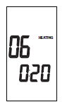
- If you set your thermostat to operate in the regulator mode, it will operate like a timer. You may adjust the amount of time the floor warming system heats during a 15-minute repeating cycle as follows:
- With the thermostat in the regulator mode, it will show the heating time and the current cycle time.
- Press the down or up button to adjust the heating time from 0 through 15.
- Example: A value of 6 will cause it to heat for 6 minutes of the 15 minute cycle, and then not heat for 9 minutes of the 15 minute cycle.
- Zero will cause it to never heat.
- 15 will cause it to heat continuously.
- 3. The cycle time shown at the bottom of the display is the current time in the
- 15-minute cycle. It repeats from 0:00 through 14:59 (min:sec).
Lockout Feature
- Your thermostat has the ability to lock out adjustment by other users. This may be useful in public locations. Only the on/off switch and the GFCI test button will then operate.
- Press the down and up button at the same time and hold for 1 second. LOCK will show on the display.
- To cancel this lockout, the down and up button must be pressed and held for 1 second. The thermostat will return to the normal operating mode.
Test the GFCI
There is a GFCI (Ground Fault Circuit Interrupter) inside the thermostat. It is designed to help protect people from possible electrical shock if the floor warming system has been damaged.
To make sure the GFCI is operating, test it after it is installed and once each month:
- Make sure the thermostat is HEATING. You may need to increase the setpoint temporarily.
- Press the GFCI Test button on the side of the thermostat. GFCI TRIP should show on the display and a red light will show next to the GFCI Test button. You should also hear a click, indicating power has been removed from the floor warming system. If any of these indicators fail, turn off the thermostat and replace it. Do not continue to use.
- To reset the GFCI, slide the On/Off switch off and back on. If the GFCI does not reset, turn the thermostat off and go to section 6 “Troubleshooting” for help.
Troubleshooting
| Problem | Solution |
| Thermostat works but no heat from the system. | 1. Check wiring connections.
2. If GFCI is tripped, reset thermostat with on/off switch. 3. Check resistances on floor warming system. See manual for system. |
|
No display. |
1. Check wiring connections.
2. Check circuit breaker or other protection “upstream” of thermostat. 3. Check the 14-pin connection on the back of the Front Module. Sometimes the pins can become misaligned when connecting the Front Module to the Power Module. |
|
GFCI is tripped. |
1. Check wiring connections.
2. Reset thermostat by switching off/on. 3. Check resistances on floor warming system. See manual for system. |
| Er 1 (only at startup) | Floor sensor not correct type or out of range. Check floor sensor resistance. |
| Er 2 | Floor sensor short-circuited. Replace sensor or Reset Factory Defaults (section 4). |
|
Er 3 |
Floor sensor not attached and thermostat in floor sense mode. Turn off power at circuit breaker and attach sensor. Or Reset Factory Defaults (section 4). |
| Er 4 or Er 5 | Internal air sensor is faulty. Replace thermostat or operate in floor sense mode. |
|
Er 6 |
Internal temperature overlimit. Make sure sunlight is not directed at the thermostat or other heat source in proximity. Otherwise, turn off power at breaker and contact factory. |
|
Er 7 |
1. Check the 14-pin connection on the back of the Front Module. Sometimes the pins can become misaligned when connecting the Front Module to the Power Module.
2. “End-of-life” indication. GFCI will no longer function correctly or safely. Reset circuit breaker, otherwise replace thermostat. |
Specifications
- Power Supply 120/240 VAC, 50/60 Hz
- Maximum Load 15 amps, resistive
- Maximum Power 1800 watts at 120 VAC
- 3600 watts at 240 VAC
- GFCI Class A (5 milliamp trip)
- Display Range 32 °F to 140 °F (0 °C to 60 °C)
- Setting Range 40 °F to 99 °F (4 °C to 37 °C)
- Accuracy ± 0.9 °F (0.5 °C)
- Storage Temp 0 °F to 120 °F (0 °C to 49 °C)
- Sensor Thermistor, 10k NTC, double-insulated
- Memory Settings retained indefinitely
- ETL Listing Control No. 3037530
- Conforms to UL 873, UL 943, CSA C22.2 No.
- 24, and CAN/CSA C22.2 No. 144
Warranty
Limited Warranty
Watts Radiant, Inc. warrants this thermostat control and sensor (the product) to be free from defects in material and workmanship for a period of (2) years from the date of original purchase from authorized dealers. During this period, Watts Radiant, Inc. will replace the product or refund the original cost of the product at Watts Radiant’s option, without charge, if the product is proven defective in normal use. Please return the thermostat to your distributor to begin the warranty process. This limited warranty does not cover shipping costs. Nor does it cover a product subjected to misuse or accidental damage. This warranty does not cover the cost of installation, diagnosis, removal or reinstallation, or any material costs or loss of use. This limited warranty is in lieu of all other warranties, obligations, or liabilities expressed or implied by the company. In no event shall Watts Radiant, Inc. be liable for consequential or incidental damages resulting from the installation of this product. Some states or provinces do not allow limitations on how long an implied warranty lasts, or the exclusion or limitation of incidental or consequential damages, so the above exclusions or limitations may not apply to you. This warranty gives you specific legal rights and you may also have other rights that vary from state to state
REFERENCE
DOWNLOAD MANUAL
SunStat 500675 Non-programmable Thermostat Owners Manual