
Stelpro STZB402+ ELECTRONIC THERMOSTAT

INTRODUCTION
WARNING
Before installing and operating this product, the owner and/or installer must read, understand and follow these instructions and keep them handy for future reference. If these instructions are not followed, the warranty will be considered null and void and the manufacturer deems no further responsibility for this product. Moreover, the following instructions must be adhered to in order to avoid personal injuries or property damages, serious injuries and potentially fatal electric shocks. All electric connections must be made by a qualified electrician, according to the electric and building codes effective in your region.
Do NOT connect this product to a supply source other than 24 VAC and do not exceed the load limits specified. Protect the heating system with the appropriate circuit breaker or fuse. You must regularly clean dirt accumulations on the thermostat. Do NOT use fluid to clean thermostat air vent. Do not install thermostat in a wet place. However, installing it in isolated walls is allowed.
Note:
When a part of the product specification must be changed to improve operability or other functions, priority is given to the product specification itself. In such instances, the instruction manual may not entirely match all the functions of the actual product.
Therefore, the actual product and packaging, as well as the name and illustration, may differ from the manual.
The screen/LCD display shown as an example in this manual may be different from the actual screen/LCD display.
DESCRIPTION
This thermostat is designed to control baseboard, convector and fan-forced heaters. It may be associated to a ZigBee network.
This thermostat is NOT compatible with the following installations
- Inductive load
- Central heating system
- Heating load outside the specified ratings (refer to the Technical Specifications section)
Parts supplied
- one (1) thermostat
- one (1) wall mounting plate located at the back of the thermostat
- two (2) mounting screws
- two (2) solderless connectors suitable for copper wires
INSTALLATION
Selection of thermostat location
The thermostat must be mounted on a wall facing the heating unit, at around 1.5 m (5 feet) above the floor level, on a section of the wall exempt from pipes or air ducts.
Do not install the thermostat in a location where temperature measurements could be altered. For example:
- close to a window, on an external wall, or close to a door leading outside
- exposed directly to the light or heat of the Sun, a lamp, a fireplace or any other heat source
- close or in front of an air outlet
- close to concealed ducts or a chimney
- in a location with poor air flow (e.g. behind a door), or with frequent air drafts conditions (e.g. head of stairs).
Thermostat mounting and connection
- Cut off power supply on lead wires at the electrical panel in order to avoid any risk of electric shock.
- If an existing thermostat is being replaced, remove the previous thermostat.
- Ensure that the air vents of the Ki thermostat are clean and clear of any obstruction.
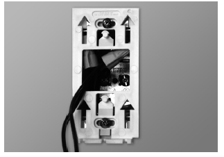
- Using a screwdriver, loosen the screw retaining the mounting base of the thermostat (do not completely remove the screw)
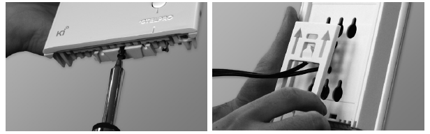
- Align and secure the mounting base to the connection box using the two screws supplied.
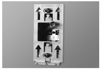
2-WIRE INSTALLATION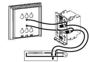
4-WIRE INSTALLATION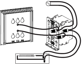
- Place all the wires into the connection box
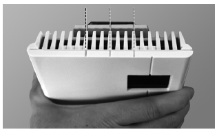
- Align the little slots located on the top of the thermostat with those on the mounting base and secure the thermostat to the mounting base. Note that you can also position the thermostat on the left or the right side of the junction box (see below). Then tighten the screw at the bottom of the unit.
OPERATION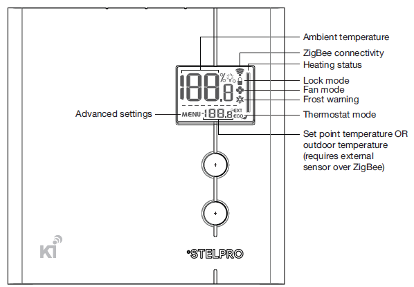
Ambient temperature
The temperature is displayed either in °C with a 0.5 °C resolution or in °F with a 1 °F resolution. The screen will display LO if the temperature drops below 0 °C (32 °F) and will display HI if the temperature rises above 50 °C (122 °F).
Temperature setpoints
The setpoint may be edited by the user using the UP and DOWN buttons located on the thermostat. The setpoint may also be modified through the ZigBee network. The minimum setpoint is 5 °C (41 °F) and the maximum setpoint is 30 °C (86 °F).
NOTE: if the setpoint is set at 7 °C (45 °F) or below, the frost warning icon will be displayed to warn the user that water pipes might be subject to freezing. Heating power indicator Whenever the thermostat is actively heating the room, the heating status graph will display the heating percentage.
- No bar: 0%
- bar: 1-25%
- bars: 26-50%
- bars: 51-75%
- bars: 76-100%
Thermostat mode
The thermostat has three modes: Comfort, Eco and Off. The first two modes have their own preestablished setpoint. Comfort: 21 °C (70 °F), Eco ( ): 17 °C (63 °F). The user may change the setpoint to any value in the range described in the setpoint section. When the Eco mode is active, the Eco icon (  ) is displayed on the LCD. When the Off mode is active, the frost warning icon is displayed on the LCD and the setpoint is replaced by ( — ). The thermostat mode may be changed locally on the thermostat by pressing the UP and DOWN buttons simultaneously for less than 3 seconds while on the main screen. The Eco setpoint is local to the thermostat and cannot be edited through the ZigBee network. If a setpoint change is sent through the ZigBee network, the thermostat mode will automatically switch to Comfort mode.
NOTE 1: Even in Off mode , the thermostat is still powered and electric shock is still possible. Always cut off the power supply when cleaning or removing the thermostat.
NOTE 2: When in Off mode , the thermostat will not activate the heating element, therefore there is a risk of freezing.
Heating mode
The thermostat has two heating modes: Baseboard/convector heater and Fan-forced heater. The Baseboard/convector heater mode will drive the load with a 15-second cycle while the Fan-forced heater mode will drive the load with a 5-minute cycle. When the Fan-forced heater mode is selected, the fan icon is displayed on the thermostat.
ZigBee connectivity ( )
)
If the thermostat is associated to a ZigBee network, the connectivity icon will be displayed on the LCD, if the device is removed from a ZigBee network, the connectivity icon will disappear. The connectivity icon may blink if there is an issue with the ZigBee radio circuit.
Advanced settings ( )
)
There are 7 advanced settings menus on the thermostat. The advanced settings are the following:
- ZigBee menu : used to associate or remove the thermostat from a ZigBee network
- Display format: used to switch the temperature format between °C and °F
- Heating mode: used to switch the heating mode between Baseboard/convector and Fanforced heaters
- Lock mode
 : used to lock the thermostat to prevent unauthorized tampering.
 - Outdoor temperature display
 : used to switch the outdoor temperature display on or off (when available). When set to (On), the outdoor temperature will be displayed if it’s available.
 - When set to (Off), the outdoor temperature will not be displayed and the setpoint will always be displayed.
- Backlight status while idle: used to set the backlight intensity when the thermostat is idle.
- 0%: the backlight will turn off after 15 seconds of inactivity
- 50%: the backlight will dim to 50% after 15 seconds of inactivity
- 100%: the backlight will always be at full intensity
- °STELPRO information menu: used to gain information on the product
- Thermostat version
- ZigBee radio version
- Day of production
- Month of production
- Year of production
- Baseboard/convector control checksum
- Fan-forced heater control checksum
- ZigBee node Id
- ZigBee network Id
- Reset to default
Modification of the settings:
- To gain access to the advanced settings root menu, press the UP and DOWN buttons simultaneously for 3 seconds.
- At this point each setting (1 to 7) may be accessed by using the UP and DOWN buttons.
- To edit a value, choose a setting then simultaneously press the UP and DOWN buttons once.
- Press the UP or DOWN button to edit the value.
- Confirm your choice by pressing the UP and DOWN buttons simultaneously one time at which point the icon will momentarily flash rapidly if a change has been made.
- To exit the advanced settings press the UP and DOWN buttons simultaneously for 3 seconds at any time. If the thermostat is left idle it will revert back to the main screen after 30 seconds
ZigBee network association ( )
Association:
Make sure the ZigBee controller is in pairing mode (refer to your ZigBee controller instruction manual). To associate the thermostat to a ZigBee network, enter Menu 1 (ZigBee menu) and either select (On) or the specific ZigBee channel used by your ZigBee controller (11 to 26). Then press the UP and DOWN buttons to start the association process. During association, (On) or the specific channel will be blinking and the connectivity icon will be animated in an increasing pattern. When the association process has been completed, the associated channel number will be displayed solid. If an error occurs, (Err) will be displayed for 3 seconds then the screen will revert to (Off).
Disassociation
To remove the thermostat from the ZigBee network, enter Menu 1 (ZigBee menu) and select (Off). Then press the UP and DOWN buttons to start the disassociation process. During disassociation, (Off) will be blinking and the connectivity icon will be animated in a decreasing pattern. When the disassociation process has been completed, (Off) will be displayed solid. If an error occurs, (Err) will be displayed for 3 seconds then the screen will revert to the associated ZigBee channel. To achieve better network performance, it is recommended to always associate your ZigBee devices starting from the closest one to the farthest one.
Factory Reset
- The thermostat may be manually reset to its original factory settings.
- When this is performed, all parameters are reset to their default values and the thermostat is removed from the ZigBee network.
- To reset the thermostat to its default settings:
- Enter the advanced settings
- Enter the °STELPRO menu (menu 7)
- Navigate to the (def) screen using the UP or DOWN buttons.
- Enter the (def) menu by pressing the UP and DOWN buttons for less than 3 seconds
- Select (yes) and confirm the selection by pressing the UP and DOWN buttons for less than 3 seconds.
- The thermostat will then reset itself.
Power Outage
If a power outage occurs, the thermostat will stop working but all configuration is saved.
Outdoor Temperature ( )
- When connected to a ZigBee network, the thermostat may display the outdoor temperature provided by an external sensor.
- When available, the outdoor temperature is displayed instead of the setpoint, providing that the outdoor temperature display setting is set to (On).
- If no temperature is received within a 4-hour timeframe, the outdoor temperature will disappear and the setpoint will be displayed.
- In order to display the outdoor temperature, an external sensor needs to be part of the ZigBee network. It may be a physical sensor or a weather station app
TROUBLESHOOTING
| PROBLEM CODE | DEFINITION |
| LO | Temperature is below 0 °C (32 °F), heating will be always active |
| HI | Temperature is above 50 °C (122 °F), heating will be always inactive |
| — | Temperature sensor is defective, heating will always be inactive. Call technical support. |
|
Err |
The connection could not be established with the ZigBee network. Make sure the thermostat is within range of the ZigBee controller or a ZigBee repeater and make sure the ZigBee controller is in association mode. |
|
E1 |
Secondary temperature sensor is defective. The thermostat will still control the temperature but performance may be diminished. Consider replacing the thermostat. |
| PROBLEM | SOLUTION |
|
The thermostat is hot |
• In normal operating conditions, the thermostat housing may become hot at maximum load. That is normal and will not affect the effective operation of the thermostat. |
| Heating is always on | • Check if the thermostat is properly connected. Refer to the installation section. |
| Heating does not run even if the thermostat indicates it is on | • Check if the thermostat is properly connected. Refer to the installation section. |
|
The display does not turn on |
• Check if the thermostat is properly connected. Refer to the installation section.
• Check the power supply at the electrical panel. • Check if the heating unit has a switch. If so, ensure that this switch is turned on. |
|
The display turns off a few minutes and then turns on again |
• The thermal protection of the heating unit has opened due to overheating. Check if the heating unit is in good operating condition and that clearance around the appliance is according to the manufacturer’s specifications. |
| The displayed ambient temperature is incorrect | • Check the presence of an air stream or a heat source near the thermostat, and correct the situation. |
| Fan-forced heater is cycling ON and OFF frequently | • Make sure the heating mode is set to Fan |
| The connectivity icon is blinking on the main screen |
• There is an issue with the ZigBee radio. Reinitialize the thermostat. |
| Setpoint and mode cannot be changed | • The thermostat is locked, turn OFF the lock mode |
TECHNICAL SPECIFICATIONS
- Supply voltage:
- 24 VAC, 50/60 Hz
- Maximum electrical current with a resistive load:
- 0.5 A
- 12 W @ 24 VAC
- Temperature display range:
- 3 °C to 40 °C (37 °F to 99.5 °F)
- Temperature display resolution:
- 0.5 °C (0.5 °F)
- Temperature set point range:
- 3 °C to 30 °C (37 °F to 86 °F)
- Temperature set point increments:
- 0.5 °C (1 °F)
- Storage temperature:
- -40 °C to 50 °C (-104 °F to 122 °F)
LIMITED WARRANTY
This unit has a 3-year warranty. If at any time during this period the unit becomes defective, it must be returned to its place of purchase with the invoice copy, or simply contact our customer service department (with an invoice copy in hand). In order for the warranty to be valid, the unit must have been installed and used according to instructions. If the installer or the user modifies the unit, he will be held responsible for any damage resulting from this modification. The warranty is limited to the factory repair or the replacement of the unit, and does not cover the cost of disconnection, transport, and installation.
E-mail: [email protected]
Web site: www.stelpro.com
REFERENCE
DOWNLOAD MANUAL
Stelpro STZB402+ ELECTRONIC THERMOSTAT User Guide