Source1 S1-THSU302-S Residential Digital Thermostat

Get To Know Your Thermostat


Display Features

- Program icon—Indicates that Time Period Programming is running or is enabled to be set.
- Clock with Day of the Week—Indicates the current time and day. This clock is also used to program the time period schedules.
- Outdoor icon—Indicates the temperature displayed is from the optional outdoor sensor.
- Room Temperature Display—Indicates the current room temperature and displays the outdoor temperature when selected.
- Mode Indicators
Selects the operational mode of the equipment.- HEAT – Indicates the heating mode.
- COOL – Indicates the air conditioning mode.
- HEAT & COOL – Indicates the system will automatically change over between heat and cool modes as the temperature varies.
- OFF – Indicates heating and cooling are turned off.
- The scrolling display will be used to help you easily navigate the setup screens in the thermostat.

- 2nd and 3rd Stage icons
Indicates what stage of cooling or heating is currently energized. - Setup Step icon
Indicates the step number when programming the thermostat - Morning, Day, Evening & Night icons
Indicates the day part of the time period program. is in the setup mode. - Desired Set Temperature
Indicates desired room temperature(s). Also displays the highest and lowest temperatures for the day. - Wi-Fi icons
One dot indicates the thermostat recognizes the wireless module. The full icon indicates the thermostat is currently connected to the Local access point, via the optional Wi-Fi Module.  icon
icon
This indicates the keypad has been locked.
- Fan On icon –
Indicates constant, continuous fan operation. When Fan On is not lit – indicates the fan will only operate when necessary to heat or to cool. - Lo icon
Indicates the lowest recorded outdoor temperature for the day.* - AuxHeat icon
Indicates 2nd stage electric strip heat is being used when the thermostat is programmed for Heat Pump operation. - Hi icon
Indicates the highest recorded outdoor temperature for the day.*
* Hi and Lo Temperatures for the day, reset at midnight.
Quick Start
During Setup and Programming
Press the WARMER or COOLER buttons to modify the selection. Press the MODE button to advance and confirm through the setup steps.
Setting the Clock and Day*
*Not available when wi-fi module is present
Press the SET CLOCK button. Adjust the clock using the WARMER or COOLER buttons. Press MODE to advance to the day setting. Adjust the day using the WARMER or COOLER buttons. Press the SET CLOCK button to confirm settings.
TIP: To adjust the time by hours press and hold the FAN button while pressing the WARMER or COOLER buttons.
Selecting the Heat or Cool Mode
Select mode by pressing the MODE button.
- Heating Only – Only the heating operation will be controlled by the thermostat in this mode.
- Cooling Only – Only the cooling operation will be controlled by the thermostat in this mode.
- Heating or Cooling (Auto-Changeover) – AUTO will automatically select heat or cool based on room temperature demand.
- OFF – OFF indicates both heating and air conditioning systems are turned off
Selecting your desired temperature
- AUTO-CHANGEOVER MODE – Pressing the WARMER or COOLER buttons in Auto mode will adjust both the heat and cool setpoints simultaneously. To adjust heat and cool setpoints individually, choose HEAT mode to adjust the heat setpoint and COOL mode to adjust the cool setpoint, then return to AUTO mode.
- HEAT OR COOL MODE – Pressing the WARMER or COOLER buttons in Heat or Cool mode will adjust only the heat or cool setpoints individually displayed.
Using the Fan Button
FAN ON indicates constant fan operation. You may turn the fan on even if the thermostat is in the OFF mode. Pressing the FAN button toggles this feature on or off. If you don’t see “Fan On”, the fan is in auto mode and will only turn on during a heat or cool demand.
Viewing the Temperature Sensors
- OUTDOOR TEMP – Press the OUTDOOR button to view the current outdoor temperature. The high and low temperatures for the day will also be displayed. The high and low temperatures reset at 12:00 am.

- Press the OUTDOOR button again to return to normal operation.
If the thermostat is connected to Skyport; upon pressing the OUTDOOR button the scrolling display will read “Forecast”. The forecasted high and low temperatures for the day will be displayed. - Press the OUTDOOR button again to view any connected wired sensor (remote or SUPPLY).
Note: If no outdoor sensor is connected, and there isn’t outdoor temperature via Wi-Fi, then 2 dashes [- -] will appear with the first button press. - REMOTE/SUPPLY TEMP – Press the Accessory Status button to view linked wireless/wired sensors and other accessories. Press the Accessory Status button to return to the main screen. Setup step 41 selects the use of the wired temperature sensor.

Installation Instructions
Remove and Replace the old thermostat
To install the thermostat properly, please follow these step-by-step instructions. If you are unsure about any of these steps, call a qualified technician for assistance.
- Assemble tools: Flat blade screwdriver, wire cutters and wire strippers.

- Make sure your Heater/Air Conditioner is working properly before beginning the installation of the thermostat.
- Carefully unpack the thermostat. Save the screws, any brackets, and instructions.
- Turn off the power to the Heating/Air Conditioning system at the main fuse panel. Most residential systems have a separate breaker for disconnecting power to the furnace.
- Remove the cover of the old thermostat. If it does not come off easily, check for screws.
- Loosen the screws holding the thermostat base or subbase to the wall and lift away.
- If you have a smartphone handy, take a photo of the wiring for future reference.
- Disconnect the wires from the old thermostat. Tape the ends of the wires as you disconnect them, and mark them with the letter of the terminal for easy reconnection to the new thermostat.
- Keep the old thermostat for reference purposes, until your new thermostat is functioning properly.
Wire Connections
If the terminal designations on your old thermostat do not match those on the new thermostat, refer to the chart below or the wiring diagrams that follow.
| The wire from the old thermostat terminal marked | Function | Install the new thermostat connector marked |
| G or F | Fan | G |
| Y1, Y | Cooling | Y1 |
| W1, W | Heating | W1/0/B |
| Rh, R, M, Vr, A | Power | R |
| C | Common | C |
| O/B | Rev. Valve | W1/O/B* |
| W2 | 2nd Stage Heat | W2 |
| Y2 | 2nd Stage Cooling | Y2 |
| W3 | 3rd Stage Heat | W3 |
| Ck1 | Dry Contact Switch | DRY CONTACT |
| CKGND | Dry Contact Switch | DRY CONTACT |
The Source 1 Thermostat Backplate
To remove the thermostat backplate: Gently separate the display from the base by pulling first from one side, then the other until the two pieces unsnap. A small screwdriver may be used, very carefully, to start separating the two pieces.


IMPORTANT: This thermostat requires both R (24 VAC Return) and C (24 VAC Common) be connected to the backplate terminals.
Check Dip Switch
Ensure which switch is correct for your system. Dip switches are located on the back of the thermostat.
- When GAS/EL or HP is set for GAS/EL: This switch (GAS or ELEC) controls how the thermostat will control the Fan (G) terminal in heating mode. When GAS is chosen, the thermostat will not energize the Fan (G) terminal in heating. When ELEC is chosen the thermostat will energize the fan in heating.

- When GAS/EL or HP is set for HP: This switch (GAS or ELEC) defines the Aux Heat type. When GAS is chosen, the auxiliary heat will not be allowed to run during heat pump operation. When ELEC is chosen, up to two stages of auxiliary strip heat will be allowed to run.
- For Heat Pump Only
When the GAS/EL or HP dip switch is configured for HP, this dip switch (O or B) must be set to control the appropriate reversing valve. If O is chosen, the W1/O/B terminal will energize in cooling. If B is chosen, the W1/O/B terminal will energize in heating.
- This dip switch configures the thermostat to control a conventional gas/electric system or a heat pump. If your system is anything other than a heat pump, leave this switch set for GAS/EL.

Sample Wiring Diagrams
Conventional Heating and Cooling Systems
Heat Pump Systems
Dry Contact
Test Operation
The Source 1 thermostat has a diagnostic feature that enables testing of all outputs. This feature is contained in Technician Setup.
To enter Technician Setup, press and hold the SETUP button for 10 seconds until all the icons appear. Follow the next steps to view settings and test equipment.
- Press MODE to view the version numbers of the thermostat.
- Press MODE again to view the jumper settings and current state of the Dry Contact terminals.
- Press MODE again and the scrolling display will read “TURN ON EQUIPMENT?” Press WARMER for Yes or COOLER for No.
- If Yes is chosen, press WARMER to turn on heat or COOLER to turn on Cooling. The scrolling display will read “NOTHING ON.” Next:
- Press WARMER to turn on and cycle up through the heating stages.
- Press COOLER to turn the heating stages off. Press MODE to exit.
- Press COOLER to turn on and cycle down through the cooling stages.
- Press WARMER to turn the cooling stages off. Press MODE to exit.
- Press MODE until “CALIBRATE SENSORS?” appears on the scrolling display. Press WARMER for Yes or COOLER for No. Press MODE to select which sensor to calibrate. Use WARMER or COOLER to modify your selection.
To exit Technician Setup at any time, press the SETUP button. Technician Setup will automatically exit after 10 minutes if no buttons are pressed.
User Setup
Backlight Operation
How to Change Settings in the Setup Screens
To enter Advanced Setup, press the SETUP button, then press MODE. Use the WARMER or COOLER buttons to adjust the value of your selection. Press MODE to advance to the next setup step. Press SETUP again to leave the setup screens.
Backlight (Setup Steps 3-8)
- Backlight (setup step 3)
- Off – Backlight turns on with any button press and turns off after 8 seconds.
- On – Backlight is on continuously.
- Backlight Intensity Level (setup step 4)
The backlight can be adjusted between Off and seven levels of brightness. - Night Dimmer (setup step 5) – Selecting On allows for automatic dimming of the display at night.
- Night Dimmer Brightness (setup step 6) Off through seven levels of brightness
- Night Dimmer Start Time (setup step 7) – 12:00 am to 12:00 am
- Night Dimmer Stop Time (setup step 8) – 12:00 am to 12:00 am
Language (Setup Step 15)
Setup step instructions on the scrolling display can be set for English, Spanish, or French. Press the SETUP button, then press MODE repeatedly until the Language setup step appears. Use the WARMER or COOLER buttons to make a selection. Press MODE to advance to the next step. Press SETUP to leave the setup screens.
Scrolling Display Method (Setup Step 16)
This option allows the user to choose how the scrolling text is displayed. Options are:
Press the SETUP button, then press MODE repeatedly until the Scrolling Method setup step appears. Use the WARMER or COOLER buttons to make selection. Press MODE to advance to the next step. Press SETUP to leave the setup screens.
Example of “Whole Words Centered”:
Vacation & Away Settings
- The Vacation feature allows the thermostat to use temporary, energy saving setpoints without having to change regular programming.

- The HOME/AWAY feature allows for a one button press to bring in your stored unoccupied vacation settings. A subsequent press of the HOME/AWAY button restores the last used comfort settings.
- Press the VACATION button to enter Vacation/Away programming.
- Use the WARMER and COOLER buttons to choose the number of days desired to run the in Vacation/Away settings.
- To confirm your settings and advance to the next step, press the MODE button again. Choose the desired Vacation/Away Mode. Press the MODE again to adjust the ‘unoccupied’ setpoint. If you selected auto changeover mode for unoccupied/vacation settings, then pressing MODE again will allow the adjusting of the 2nd setpoint.
- Otherwise press MODE to confirm and return to normal operation.
- Press the VACATION button again to return to the main screen. Both VACATION and
- AWAY use these same settings. VACATION button use specifies a duration of days for these settings, whereas Away maintains these settings until the HOME/AWAY button is pressed again.
- When the VACATION button is pressed and the thermostat detects that a Wi-Fi module is installed:
- During Non-Vacation Periods: the scrolling display will read: “Use Skyport to View/Edit Settings”.
- During Vacation Period: the scrolling display will read: “To cancel VACATION press MODE button”
NOTE: If the HOME/AWAY button is pressed during an active VACATION period, the scrolling display will read: “To cancel VACATION press MODE button. The thermostat must be running in Program On for VACATION to have any effect. After you alter any settings, they will take effect until midnight on that day. The thermostat does not need to be running in Program On for the HOME/AWAY button to have effect.
Emergency Heat
The Emergency Heat function is only available if your thermostat is set to control a Heat Pump. To initiate the Emergency Heat feature, Press the EMERGENCY button. During Emergency Heat operation the thermostat will turn on the fan and auxiliary stages of heat when there is a demand for heat. The compressor used for heating and all stages of cooling will be unavailable. To exit Emergency Heat, press the EMERGCY button.
Wireless Module
The ACCESSORY STATUS button allows the user to view the status of wired and wireless accessories. For many of wireless devices this status includes Battery Level, Signal Strength, and Last Time Updated. If there is an optional wireless module installed, the ACCESSORY SETUP button allows the user to link or connect wireless devices to the thermostat, or the thermostat to the network.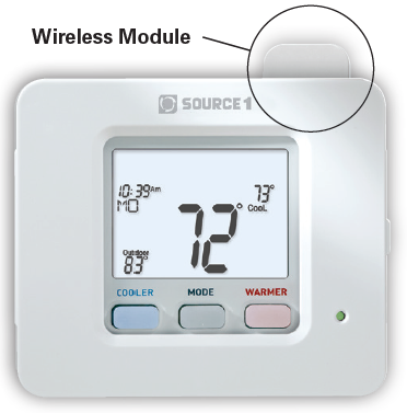
Service Filter
These setup steps allow the user to monitor equipment runtimes and program service alerts. Service alerts are displayed in the scrolling marquee.
Service Filter Runtime (Setup Steps 9-10, 12-13)
- Current Service Filter Runtime Hours (Setup Step 9) – This counter keeps track of the number of hours of fan runtime in the Heating mode, Cooling mode, and in stand-alone Fan operation. Press FAN to reset.
- Current Service Filter Calendar Days (Setup Step 10) – This counter displays the total number of calendar days that have elapsed since the counter was reset to help the user track Fan runtime. Press FAN to reset.
- Set Service Filter Runtime Hours (Setup Step 12) – This timer allows the user to specify the number of hours the fan will run before the “Replace Filter” alert will be displayed. Press COOLER continuously until 0 is displayed to disable this alert.
- Set Service Filter Calendar Days (Setup Step 13) – This timer allows the user to specify the number of calendar days that will elapse before the “Replace Filter” alert will be displayed. Press COOLER continuously until 0 is displayed to disable this feature.
Press the SETUP button, then press MODE repeatedly until the desired setup step appears. Use the WARMER or COOLER buttons to make a selection. Press MODE to advance to the next step. Press SETUP to leave the setup screens.
Runtimes
- To view, set, or reset System Runtimes, press the SETUP button, then press MODE. Press MODE to advance to the desired setup step.
- Use the WARMER or COOLER buttons to adjust the value of your selection. Press SETUP again to leave the setup screens.
UV Lamp Runtime (setup steps 11, 14)
- Current UV Lamp Calendar Days (Setup Step 11) – This counter displays the total number of calendar days that have elapsed to help the user track UV lamp runtime. Press FAN to reset.
- Set UV Lamp Calendar Days (Setup Step 14) – This timer allows the user to specify the number of calendar days the UV Lamp will operate before the “Replace UV Lamp”alert will be displayed. Press COOLER continuously until 0 appears to disable this alert.
Time Period Programming
Programming a Daily Time Period Schedule*
*not available when wi-fi module is present
To enter Time Period Programming screens, Press and hold PROGRAM until the scrolling prompt appears.
- OFF – Time Period Program is off.
- RUN – Time Period Program is running.
- HOLD TO SET – Press and hold PROGRAM to make Time Period Programming changes.
Select Day of Week to program – Press the WARMER or COOLER buttons to choose the day of the week. Press MODE to advance to the next step.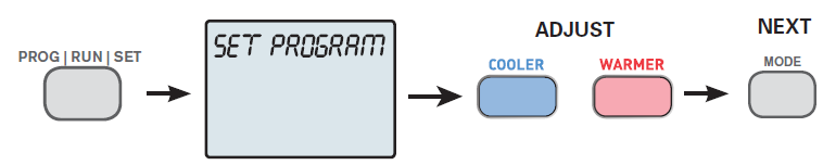
This thermostat features four programmable time periods per 24-hour day: Morning, Day, Evening, and Night. The start time for each time period is adjustable. The stop time for each time period is the start time for the next period. Each time period or day part may be individually disabled.
- Select the Day to Program – Press the WARMER or COOLER to select the desired Day or Week Part in the case of 5-2 (weekday – weekend) programming.
- Enable/Disable Morning Period – Press the WARMER or COOLER to select ON or OFF. If the default ON is selected, then the Morning period will run complete with the Mode and Set Points selected. If OFF is selected then the Morning day part will be skipped and the thermostat will use the next day part that is enabled.
- Select Morning Mode – Press the WARMER or COOLER to select the desired mode, which includes OFF. You may be limited by the available modes in advanced Installer setup step#2. Press MODE to advance to the next step.
- Select Morning Start Time – Press the WARMER or COOLER buttons to adjust the time of day desired. Press MODE to advance to the next step.
- Select Morning Cool Setpoint – Press the WARMER or COOLER buttons to adjust the cool setpoint desired. This step will appear if Cool or Auto Mode was selected in the step where the Morning mode is specified. Press MODE to advance to the next step.
- Select Morning Heat Setpoint – Press the WARMER or COOLER buttons to adjust the heat setpoint desired. This step will appear if Heat or Auto Mode was selected in the step where the Morning mode is specified. Press MODE to advance to the next step.
Repeat Enable, Mode, Start Time and Setpoint programming for Day, Evening, and Night.
“Copy Current Day to Next Day” is available – Press the UP button to Copy the current day’s program to the next day. Press Mode again to continue copying the following day.
Press the PROGRAM Button to exit Time Period Programming at any time.
Installer Setup
How to Change Settings in the Setup Screens
To enter Advanced Setup, press the SETUP button, then press MODE. Use the WARMER or COOLER buttons to adjust the value of your selection. Press MODE to advance to the next setup step. Press SETUP again to leave the setup screens.
Selecting Your Time Period Schedule (setup step 1)
This thermostat may be configured to be programmable or nonprogrammable.
- 7-Day Program – Allows all seven days to be programmed independently.
- Non-Program – No advanced time period programming available.
- 1-Day Program – Allows one 24-hour day to be programmed. This same schedule will be repeated every day the program is set to run.
- 5/2 Day Program – Allows weekdays, and weekends to be programmed independently.
Selecting Your Available Modes (setup step 2)
- Auto-Changeover – Allows the thermostat to turn on heating or cooling based on room temperature demand. Also allows the manual selection of HEAT only or COOL only and OFF.
- Heat and Cool – Allows the thermostat to turn on heating or cooling depending on which one has been manually selected. Auto-Changeover is not available when this is selected.
- Heat Only – Allows the thermostat to only turn on the HEAT or OFF modes.
- Cool Only – Allows the thermostat to only turn on COOL or OFF modes.
Setpoint Limits (setup step 17)
When this feature is set to USE, the heat and cool setpoints can be restricted to preset levels, set in steps 18 and 19.
- Maximum Heat Setpoint (Setup Step 18) – (35˚ – 99˚).
- Minimum Cool Setpoint (Setup Step 19) – (35˚ – 99˚).
Cycles Per Hour (setup step 20)
The Cycles Per Hour setting may limit the number of times per hour your HVAC unit may energize. For example, at a setting of 6 cycles per hour the HVAC unit will only be allowed to energize once every 10 minutes. The Cycles Per Hour limit may be overridden and reset by pressing the WARMER or COOLER buttons on the thermostat. Settings are No Limit, 2, 3, 4, 5, or 6.
Compressor Minimum Off Minutes (setup step 21)
This feature allows the user to set a minimum off time for the compressor. Settings are 5 mins., 3 mins., or 0 mins.
Minimum Heat/Cool Setpoint Difference (setup step 22)
This feature allows the user to set the minimum gap between Heat and Cool setpoints in AUTO mode. Select from 0 to 6. If setup step 2 is not set for AUTO-CHANGEOVER, this step will not appear.
Number of Heat Stages (setup step 23)
This setting assures proper stage callouts on the thermostat display for non-heat pump applications.
Number of Cool Stages (setup step 24)
This setting assures proper stage callouts on the thermostat display for non-heat pump applications.
Number of Compressor Stages (setup step 25)
This feature is for heat pump applications only. This feature allows the thermostat to control 1 or 2 compressor stages when configured for heat pump.
Number of Aux Stages (setup step 26)
This feature is for heat pump application only. This feature allows for proper Aux Heat Staging. (0-2 stages)
Deadband Settings (setup steps 27 – 36)
The Deadband is the number of degrees or minutes that the thermostat waits before it initiates the stages of heating or cooling.
- 1st Stage Deadband (Setup Step 27) – Specifies the minimum temperature difference between the room temperature and the desired setpoint before the first stage of heating or cooling is allowed to turn on. (1 – 6 degrees) For example, if the heat setpoint is 68˚ and the 1st Stage deadband is set to 2 degrees, the room temperature will need to reach 66˚ before the heat turns on.
- 2nd Stage Deadband (Setup Step 28) – Specifies the additional minimum temperature difference after the first stage turns on before the second stage is activated. (0˚ – 10˚)
- 3rd Stage Deadband (Setup Step 29) – Specifies the additional minimum temperature difference after the second stage turns on before the third stage is activated. (0˚ – 10˚)
- 4th Stage Deadband (Setup Step 30) – (Two Stage heat pump only) – Specifies the additional minimum temperature difference after the third stage turns on before the final stage of strip heat is activated. (0˚ – 10˚)
- Minutes Between 1st and 2nd Stage (Setup Step 31) – Specifies the minimum time (in minutes) after the first stage turns on before the second stage can turn on. (0 – 60)
- Minutes Between 2nd and 3rd Stage (Setup Step 32) – Specifies the minimum time (in minutes) after the second stage turns on before the third stage can turn on. (0 – 60)
- Delay Between 3rd and 4th Stage (Setup Step 33) – Specifies the minimum time (in minutes) after the third stage turns on before the final stage can turn on. (0 – 60)
- Second Stage Turnoff Point (Setup Step 34) – Specifies whether second stage will turn off at first stage deadband or remain on until the room temperature demand is satisfied. Choose between Deadband or Setpoint.
- Third Stage Turnoff Point (Setup Step 35) – Specifies whether third stage will turn off at second stage deadband or remain on until the room temperature demand is satisfied. Choose between Deadband or Setpoint.
- Fourth Stage Turnoff Point (Setup Step 36) – Specifies whether fourth stage will turn off at third stage deadband or remain on until the room temperature demand is satisfied. Choose between Deadband or Setpoint.
Programming the Fan (setup steps 37 – 40)
- Fan Program (Setup Step 37) – This feature allows the fan to be programmed to turn on automatically for a specified amount of time during the day. If this feature is set to ON, the next three steps will appear.
- Minutes of Fan Runtime Per Hour (Setup Step 38) – This setting specifies the number of minutes (0 – 60, in increments of 5) that the fan will run at the top of each hour.
- Fan Program Start Time (Setup Step 39) – This setting specifies the hour of each day when the programmable fan feature will start.
- Fan Program Stop Time (Setup Step 40) – This setting specifies the hour of each day when the programmable fan feature will stop. NOTE: Setting the Stop Hour equal to the Start Hour will cause the fan to run 24 hours a day.
Wired Sensor Type (setup step 41)
Specifies the use of the connected, wired sensor. The choices are: Remote or Supply. Only the remote option allows control of the sensor.
Fan Off Delay in Seconds (setup step 44)
This feature allows the user to increase the cooling or electric strip heating efficiency of the system. The thermostat may be programmed to continue running the fan after a call for cooling or electric strip heating has been satisfied. This delay can be set for 0, 30, 60, 90, or 120 seconds. If set to 0, the fan will not run after a call for cooling or electric strip heating has been satisfied.
Comfort Recovery (setup step 46)
With Comfort Recovery on, the thermostat will attempt to reach the Morning 1 setpoint temperature at the exact time programmed into the thermostat. Comfort Recovery, only works when the thermostat enters the Morning mode from the Night mode. For example, if the Morning program is set for 6am at 72°F heating and 75°F cooling, the thermostat will turn the system on before 6am in an effort to bring the temperature to its correct setting at exactly 6am. The thermostat learns from experience, so please allow 4-8 days after a program change or after initial installation to give Comfort Recovery time to adjust. If used with a heat pump, electric strip heat will be disabled while Comfort Recovery is active.
Control to Temp Source (setup step 42)
This feature allows the use to specify which temperature sensor source(s) to be used to measure room temperature for control
- Thermostat: Uses the internal thermostat sensor only.
- Wired Remote: Uses external temperature sensor wired to the REMOTE SENSOR contacts.
- Wireless Remote: Uses one wireless remote temperature sensor. Choose which linked sensor to use in the subsequent step.
- Average of Wireless Remotes: Averages the temperatures of all linked wireless remote sensors.
- Average Thermostat and Wired Remote: Averages the temperatures of the wired remote sensor and the thermostat.
- Average All Sensors: Averages the temperatures of the wired remote, any linked wireless remotes and the thermostat.
Wireless Remote to use (setup step 43)
Specifies the use of the connected, wired sensor. The choices are: Remote or Supply. The remote option allows control to the sensor, the supply does not.
Fahrenheit or Celsius (setup step 45)
This feature allows the thermostat to display temperature in Fahrenheit or Celsius.
Press Fan to Clear All Messages (setup step 59)
This feature allows the user to clear all current error messages from the display.
Dry Contact Operation
Dry Contact Polarity (Setup Step 47)
- Open (Normally Open) – The dry contact is open until the connected device closes the circuit.

- Closed (Normally Closed) – The dry contact is closed until the connected device opens the circuit.

Dry Contact Use (setup step 48)
- CONDENSATE – If CONDENSATE is selected when the dry contact is active, the thermostat will lockout the compressor terminal(s), and “CONDENSATE PAN OVERFLOW” will appear on the display.
- VACATION – If VACATION is selected when the dry contact is active, the thermostat will be forced into AWAY/unoccupied settings.
- FDD – If FDD is selected when the dry contact is active, the scrolling display will read “Equipment fault”. This error message will disappear when the Dry Contact is idle.
Skyport (Setup step 49)
Set to ON to allow access to Skyport services or to OFF to not allow access to Skyport services. (Wifi accessory is required) Visit source1.skyportcloud.com/ for more information.
Local API (Setup step 50)
Set to ON to allow third-party software to interface with your thermostat. Typically used with home automation set-ups. (Wifi accessory is required)
Automated Demand Response
Overview
Source 1 thermostats support the handling of specific signals from the utility provider. The utility-generated signals carry pricing information and/or setback actions that alter the comfort settings of the thermostat in order to reduce energy usage on demand. This is known as Automated Demand Response or ADR for short. You must register to participate in a utility-sponsored program, if offered by your local utility, to take advantage of this feature.
Skyport Cloud Services
From the web application, the user will select Thermostat Settings from the left column. Then the Demand Response button is selected.

The Demand Response configuration page, shown below, is where the thermostat is configured to respond to the energy provider’s signals. It also sets operational parameters for the thermostat. The left column of the ADR configuration page allows or prevents access by the utility. Here communication with the utility and your thermostat may be turned On or Off.
Selecting the Overview tab of the ADR page will cause a summary of ADR events to be displayed.
- ADR (setup step 51)
Controls whether you want the thermostat to possibly respond to signals from the utility provider. Select ON to allow this and to have steps 52-58 appear. - ADR Action (setup step 52)
Allows the user to determine what action is taken when an ADR event is received.- Observe Setpoint Offsets – will offset the heat and cool setpoints by the amounts specified in setup steps 57 and 58
- Observe Static Setpoints – will set the heat and cool setpoints to thevalues specified in setup steps 55 and 56
- Event Max Cool Setpoint (setup step 53)
- Event Min Heat Setpoint (setup step 54)
Specifies the range of allowable setpoint adjustments to be enforced when any ADR signal has been received from the utility. Since you might be paying more for energy while an event is active, you can impose tighter limits on setpoint ranges that are only enforced during the event.
- Static Cool Setpoint (setup step 55)
- Static Heat Setpoint (setup step 56)
Specifies the setpoints that will come into use during an event when the ADR ACTION is set to OBSERVE STATIC SETPOINTS. - Cool Setpoint Offset (setup step 57)
- Heat Setpoint Offset (setup step 58)
Specifies how much the current setpoints in effect prior to an event will be altered during an event when the ADR ACTION is set to OBSERVE SETPOINT OFFSETS. The heat setpoint can be automatically lowered by -1 to -10 degrees while the cool setpoint can be automatically raised by 1 to 10 degrees.
DISPLAY INDICATIONS WHEN AN ADR EVENT IS HAPPENING
After setting your desired values for use during an ADR event, the scrolling display will give a little information when an event is pending or active. For instance, when an ADR event has been sent to your thermostat, you might see ADR STARTS 8/14 at 2:00pm to notify you of a pending event. Once active, you might see ADR STOPS 8/14 at 6:00pm. When an event is active, you can press any of COOLER, WARMER or MODE buttons, followed by the WARMER to opt out of the event.
Locking/Unlocking the Keypad
To prevent unauthorized use of the thermostat, the front panel buttons may be disabled. To disable, or ‘lock’ the keypad, press and hold the MODE button. While holding the MODE button, press the WARMER and COOLER buttons together. The icon will appear on the display, then release the buttons.
To unlock the keypad, press and hold the MODE button. While holding the MODE button, press the WARMER and COOLER buttons together. The icon will disappear from the display, then release the buttons.
Resetting the Thermostat to the Factory Default Settings (for default values, Advanced Setup Table) If, for any reason, you desire to return all the stored settings back to the factory default settings, follow the instructions below.
WARNING: This will reset all Time Period and Advanced Programming to the default settings. Any information entered prior to this reset will be permanently lost.
- Press and hold SETUP for 10 seconds. All icons will appear on the display.

- After all the icons appear, release SETUP. Press and hold FAN for 5 seconds. DEFAULTS will appear on the display.

- After DEFAULTS appears, release FAN. Press MODE to return to normal operation.

Technician Setup
To enter Technician Setup, press and hold the SETUP button for 10 seconds. After all the icons appear, press MODE. The version number of the thermostat will appear in the scrolling text. Press MODE to advance to the next step. Use the WARMER or COOLER buttons to adjust the value of your selection. To leave Technician Setup, press SETUP.
Technician Setup is for diagnostic and testing purposes and is intended for use by a qualified technician.
Technician Setup contains the following options:
- View the version number of the thermostat.
- View the jumper setting of J1 (Gas/Electric or Heat Pump), J2 (Reversing Valve: RV=O or RV=B), and J3 (Fan: Gas or Electric) jumpers located on the back of the thermostat. (Remove the thermostat from backplate for access)
- View the state of the Dry Contact and Fault terminals.
- Turn on equipment outputs for testing.
- Calibrate thermostat and remote sensors.
Advanced Setup Table
| Step# Description | Pg# | Range | Df | |
| 1 | Prog Mode | 24 | Non, 1 Day, 5/2 Day, 7 Day | 7 |
| 2 | Available Modes | 24 | Heat/Cool/Auto/Off, Heat/Cool /Off, Heat/Off, Cool/Off | Heat/Cool /Auto/Off |
| 3 | Backlight | 16 | On, Off | Off |
| 4 | Backlight Level | 16 | Off thru 7 levels of brightness | Level 5 |
| 5 | Night Dimmer | 16 | On/Off | Off |
| 6 | Night Dimmer Brightness | 16 | Off thru 7 levels of brightness | 2 (20%) |
| 7 | Night Dimmer Start Time | 16 | 12A-12A | 8:00P |
| 8 | Night Dimmer Stop Time | 16 | 12A-12A | 6:00A |
| 9 | Current Service Filter Runtime Hours | 20 | 0-1999 Hours | 0 |
| 10 | Current Service Filter Calendar Days | 20 | 0-720 Days | 0 |
| 11 | Current UV Lamp Calendar Days | 21 | 0-720 Days | 0 |
| 12 | Set Service Filter Runtime Hours | 20 | 0-1950 hours | 0 |
| 13 | Set Service Filter Calendar Days | 20 | 0-720 Days | 0 |
| 14 | Set UV Lamp Calendar Days | 21 | 0-720 Days | 0 |
| 15 | Language | 16 | English, Espanol, Francais | English |
| 16 | Scrolling Method | 17 | “L-R Slow, L-R Fast, Word L-R Slow, Word L-R Fast, Whole Word L Slow, Whole Word R Slow, Whole Word Ctr. Fast, Whole Word Ctr. Slow” | “Whole Words Center Fast” |
| 17 | Setpoint Limits | 25 | No, Use | No |
| 18 | Max Heat Setpoint | 25 | 35 – 99 Degrees | 74 |
| 19 | Min Cool Setpoint | 25 | 35 – 99 Degrees | 70 |
| 20 | Cycles Per Hour | 25 | No Limit, 2, 3, 4, 5, 6 | 6 |
| 21 | Compressor Minimum Off Minutes | 25 | 0, 3, 5 Minutes | 5 |
| 22 | Min. Heat/Cool Setpoint Difference | 25 | 0 – 6 Degrees | 2 |
| 23 | Number of Heat Stages | 25 | 0 – 3 | 2 |
| 24 | Number of Cool Stages | 25 | 0 – 2 | 1 |
| 25 | Number Of Compressor Stages | 25 | 1, 2 | 1 |
| 26 | Number of Aux Stages | 25 | 0, 1, 2 | 0 |
| 27 | 1st Stage Deadband | 26 | 1 – 6 Degrees | 2 |
| 28 | 2nd Stage Deadband | 26 | 0 – 10 Degrees | 2 |
| 29 | 3rd Stage Deadband | 26 | 0 – 10 Degrees | 2 |
| 30 | 4th Stage Deadband | 26 | 0 – 10 Degrees | 2 |
| 31 | Minutes Between 1st and 2nd Stage | 26 | 0 – 60 Minutes | 2 |
| 32 | Minutes Between 2nd and 3rd Stage | 26 | 0 – 60 Minutes | 2 |
| 33 | Minutes Between 3rd and 4th Stage | 26 | 0 – 60 Minutes | 2 |
| 34 | 2nd StageTurnoff Point | 26 | Deadband, Setpoint | Deadband |
| Step# Description | Pg# | Range | Df | |
| 35 | 3rd StageTurnoff Point | 26 | Deadband, Setpoint | Deadband |
| 36 | 4th Stage Turnoff Point | 26 | Deadband, Setpoint | Deadband |
| 37 | Fan Program | 27 | On, Off | Off |
| 38 | Minutes of Fan Runtime | 27 | 0-60 | 0 |
| 39 | Fan Program Start Time | 27 | 12:00A – 12:00A | 7:00A |
| 40 | Fan Program Stop Time | 27 | 12:00A – 12:00A | 9:00A |
| 41 | Wired Sensor Type | 27 | Remote, Supply | Remote |
| 42 | Control to Temp Source | 28 | Thermostat, Wired Remote*, Wireless Remote, Average of Wireless Remotes, Average Thermostat, and Wired Remote*, Average All Sensors.
*Option only if prior step = “Remote” |
Thermostat |
| 43 | Wireless Remote to Use | 28 | list of wifi sensors currently linked to the thermostat. * This step only appears if the prior step = “Wireless Remote” |
first linked sensor in list |
| 44 | Fan Off Delay | 27 | 0 – 120 Seconds | 0 |
| 45 | F/C | 28 | Fahrenheit (F), Celsius (C) | F |
| 46 | Comfort Recovery | 27 | On, Off | Off |
| 47 | Dry Contact Polarity | 29 | Open, Closed | Open |
| 48 | Dry Contact Use | 29 | Condensate, Vacation, FDD | Vacation |
| 49 | Skyport | 29 | On, Off | On |
| 50 | Local API | 29 | On, Off | Off |
| 51 | ADR | 33 | On, Off | On |
| 52 | ADR Action | 33 | Observe Setpoint Offset,Observe Static Setpoints | Observe set-point offsets |
| 53 | Event Max Cool Setpoint | 33 | 65 – 90 | 90 |
| 54 | Event Min Heat Setpoint | 33 | 50 – 85 | 50 |
| 55 | Static Cool Setpoint | 33 | 65 – 85 | 82 |
| 56 | Static Heat Setpoint | 33 | 65 – 85 | 60 |
| 57 | Cool Setpoint Offset | 34 | 1 to 10 | 4 |
| 58 | Heat Setpoint Offset | 34 | -1 to -10 | -4 |
| 59 | Press Fan To Clear All Messages | 28 | ||
Troubleshooting
- SYMPTOM: The air conditioning does not attempt to turn on.
CAUSE: The compressor timer lockout may prevent the air conditioner from turning on for a period of time.
REMEDY: Consult the Owner’s Manual in the Installer Setup section to defeat the Cycles Per Hour. - SYMPTOM: The display is blank.
CAUSE: Lack of proper power.
REMEDY: Make sure the power is on to the furnace and that you have 24vac between R & C. - SYMPTOM: The air conditioning does not attempt to turn on.
CAUSE: The cooling setpoint is set too high.
REMEDY: Lower the cooling setpoint or lower the cooling set-point limit. See Setpoint Limits. - SYMPTOM: The heating does not attempt to turn on.
CAUSE: The heating setpoint is set too low.
REMEDY: Raise the heating setpoint or raise the heating set-point limit. See Setpoint Limits . - SYMPTOM: When controlling a residential heat pump, and asking for cooling, the heat comes on.
CAUSE: The thermostat reversing valve jumper is set for “B”.
REMEDY: Set the reversing valve jumper for “O”. - SYMPTOM: When calling for cooling, both the heat and cool come on.
CAUSE: The thermostat equipment jumper is configured for “HP” and the HVAC unit is a Gas/Electric.
REMEDY: Set the equipment jumper for “Gas”. - SYMPTOM: When the Program button is pressed, the display reads “DISABLED”.
CAUSE: Program mode is set to “NON PROGRAM”.
REMEDY: Set Program Mode (Setup 1) to 1, 5/2, or 7 Day. See Selecting Your Program Mode.
Warranty
One-Year Warranty – This Product is warranted to be free from defects in material and workmanship. If it appears within one year from the date of original installation, whether or not actual use begins on that date, that the product does not meet this warranty, a new or remanufactured part, at the manufacturer’s sole option to replace any defective part, will be provided without charge for the part itself provided the defective part is returned to the distributor through a qualified servicing dealer. THIS WARRANTY DOES NOT INCLUDE LABOR OR OTHER COSTS incurred for diagnosing, repairing, removing, installing, shipping, servicing or handling of either defective parts or replacement parts. Such costs may be covered by a separate warranty provided by the installer.
THIS WARRANTY APPLIES ONLY TO PRODUCTS IN THEIR ORIGINAL INSTALLATION LOCATION AND BECOMES VOID UPON REINSTALLATION.
LIMITATIONS OF WARRANTIES – ALL IMPLIED WARRANTIES (INCLUDING IMPLIED WARRANTIES OF FITNESS FOR A PARTICULAR PURPOSE AND MERCHANTABILITY) ARE HEREBY LIMITED IN DURATION TO THE PERIOD FOR WHICH THE LIMITED WARRANTY IS GIVEN. SOME STATES DO NOT ALLOW LIMITATIONS ON HOW LONG AN IMPLIED WARRANTY LASTS, SO THE ABOVE MAY NOT APPLY TO YOU. THE EXPRESSED WARRANTIES MADE IN THIS WARRANTY ARE EXCLUSIVE AND MAY NOT BE ALTERED, ENLARGED, OR CHANGED BY ANY DISTRIBUTOR, DEALER, OR OTHER PERSON WHATSOEVER.
ALL WORK UNDER THE TERMS OF THIS WARRANTY SHALL BE PERFORMED DURING NORMAL WORKING HOURS. ALL REPLACEMENT PARTS, WHETHER NEW OR REMANUFACTURED, ASSUME AS THEIR WARRANTY PERIOD ONLY THE REMAINING TIME PERIOD OF THIS WARRANTY.
THE MANUFACTURER WILL NOT BE RESPONSIBLE FOR:
- Normal maintenance as outlined in the installation and servicing instructions or owner’s manual, including filter cleaning and/or replacement and lubrication.
- Damage or repairs required as a consequence of faulty installation, misapplication, abuse, improper servicing, unauthorized alteration or improper operation.
- Failure to start due to voltage conditions, blown fuses, open circuit breakers or other damages due to the inadequacy or interruption of electrical service.
- Damage as a result of floods, winds, fires, lightning, accidents, corrosive environments or other conditions beyond the control of the Manufacturer.
- Parts not supplied or designated by the Manufacturer, or damages resulting from their use.
- Manufacturer products installed outside the continental U.S.A., Alaska, Hawaii, and Canada.
- Electricity or fuel costs or increases in electricity or fuel costs for any reason whatsoever including additional or unusual use of supplemental electric heat.
- ANY SPECIAL INDIRECT OR CONSEQUENTIAL PROPERTY OR COMMERCIAL DAMAGE OF ANY NATURE WHATSOEVER. Some states do not allow the exclusion of incidental or consequential damages, so the above may not apply to you.
This warranty gives you specific legal rights and you may also have other rights which may vary from state to state.
Technical Specifications
S1-THSU302-S Thermostat Controllers
| Power Requirements | 20 – 30 VAC 50/60 Hz, 3.0 VA @ 24V nominal. | |
| Output Rating | W1, W2, W3 = 0.2A max, 0.01A min, 3A inrush, 20 – 30 VAC Y1, Y2, G = 0.4A max, 0.01A min, 3A inrush, 20 – 30 VAC | |
| Local Temperature Sensor Type | Thermistor, NTC 10K @ 25˚C | |
| Remote Temperature Sensor Type | Thermistor, NTC 10K @ 25˚C | |
| Wire Size | 16 AWG (100 ft max) to 24 AWG (36 ft max) | |
| Temperature Adjustment Range | 35˚ to 99˚ deg F (2˚ to 36˚ deg C) | |
| Accuracy | 35˚ to 65˚ deg F +/- 3˚ degF, greater than 65˚ to less than 80 degF +/- 2 degF, 80˚ to 99˚ deg F +/- 3˚ degF, greater than 99˚ to 104˚ deg F +/- 5˚ deg F | |
| Deadband | Adjustable 1˚ to 6˚ deg first stage, 0˚ – 10˚ deg 2nd & 3rd stages | |
| Ambient Conditions | Operating | 35˚ to 104˚ deg F (2˚ to 40˚ deg C), 5 – 95% RH non-condensing, 86˚ deg F max dew point |
| Storage | -22˚ to 122˚ deg F (-30˚ to 50˚ deg C), 5-95% RH non-condensing, 86˚ deg F max dew point | |
| Compliance | UL/cUL listed, file E468676, NEC Class 2 | |
| Dimensions | 4.4” H x 5.2” W x 1.0”D | |
| Shipping Weight | 0.34 kg | |
CAUTION Follow the Installation Instructions before proceeding. Set the thermostat mode to “OFF” prior to changing settings in setup or restoring Factory Defaults.
This Source 1 thermostat has the ability to receive updates to its firmware. Periodically firmware updates are released by the manufacturer to add features and/or performance enhancements. This manual was produced reflecting the most current firmware/feature set at the time of publication, firmware rev. 12. Firmware releases after rev. 12 may not be adequately depicted in this manual. Please refer to the appropriate website or contact your place of purchase to learn about changes to the thermostat after firmware release 12.
Glossary of Terms
- Auto-Changeover: A mode in which the thermostat will turn on the heating or cooling based on room temperature demand.
- Cool Setpoint: The warmest temperature that the space should rise to before cooling is turned on (without regard to deadband).
- Deadband: The number of degrees the thermostat will wait, once a setpoint has been reached, before energizing heating or cooling.
- Differential: The forced temperature difference between the heat setpoint and the cool setpoint.
- Heat Setpoint: The coolest temperature that the space should drop to before heating is turned on (without regard to deadband).
- Icon: The word or symbol that appears on the thermostat display.
- Mode: The current operating condition of the thermostat (i.e. Off, Heat, Cool, Auto, Program On).
- Non-Programmable Thermostat: A thermostat that does not have the capability of running Time Period Programming.
- Programmable Thermostat: A thermostat that has the capability of running Time Period Programming.
- Temperature Swing: Same as Deadband.
- Time Period Programming: A program that allows the thermostat to automatically adjust the heat setpoint and/or the cool setpoint based on the time of the day.
REFERENCE:
DOWNLOAD MANUALS:
Source1 S1-THSU302-S Residential Digital Thermostat Owners Manual

Source1 S1-THSU302-S Residential Digital Thermostat Owners Manual