Source1 S1-THEC11NS Non-Programmable Thermostat

Safety Warnings
CAUTION Follow Installation Instructions carefully.
DISCONNECT POWER TO THE HEATER – AIR CONDITIONER BEFORE REMOVING THE OLD THERMOSTAT AND INSTALLING THE NEW THERMOSTAT.
CAUTION
The two Alkaline “AA” batteries must be replaced at least once every 12 months to ensure proper operation. The “Low Battery” icon will appear on the thermostat display when it is time to replace the batteries. If the thermostat is connected to 24v power, the batteries should still be installed, but are not required. When “Low Battery” is displayed the batteries must be replaced immediately. The manufacturer cannot be liable for improper operation of the thermostat if the batteries are not immediately replaced. Annual battery replacement is especially critical in locations subject to freezing temperatures. The thermostat will be unable to turn on the heating system if the batteries are exhausted.
This device complies with Part 15 of the FCC rules.
Operation is subject to the following two conditions:
- This device may not cause harmful interference, and
- this device must accept any interference received, including interference that may cause undesired operation.
Location of Controls

Display
- Heat and Cool Indicators.
- In normal operation, Heat or Cool appears, depending on the Mode Switch position. When heat or cool is energized, the Heat or Cool indicator will flash.
- Current room or set temperature.
- Desired set temperature indicator.
- When this indicator is on, the large numbers represent the desired room temperature. Pressing the COOLER or WARMER button during normal operation will cause the large numbers to switch from the current room temperature to the desired set temperature.
- Indicates battery life is low; it is recommended to replace the batteries at this time.

Normal Operation
Operation
- Select Cool or Heat with the Mode Switch. Normally leave the fan switched to Auto.
- In Fan Auto, the fan will turn on only with a heat or cool demand. When Fan On is selected, the fan will run continuously.
- Adjust the desired set temperature with the COOLER or WARMER buttons.

Fahrenheit or Celsius
Operation
- Select Off with the Mode Switch.
- Press and hold the COOLER and WARMER buttons at the same time until the temperature is displayed in degrees Celsius.
- Repeat this process to display the temperature in degrees Fahrenheit

Preparation
Proper installation of the thermostat will be accomplished by following these step-by-step instructions. If you are unsure about any of these steps, call a qualified technician for assistance
These tools will be required: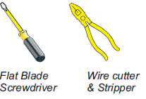
- Make sure your Heater/Air Conditioner is working properly before beginning the installation of the thermostat.
- Carefully unpack the thermostat. Save the screws and instructions.
- Turn off the power to the Heating/Air Conditioning system at the main fuse panel. Most residential systems have a separate breaker for disconnecting power to the furnace.
Remove & Replace the Old Thermostat
- Remove the cover of the old thermostat. If it does not come off easily check for screws.
- Loosen the screws holding the thermostat base or subbase to the wall, and lift away.
- Disconnect the wires from the old thermostat.
- Tape the ends of the wires as you disconnect them, and mark them with the letter of the terminal for easy reconnection to the new thermostat.
- Keep the old thermostat for reference purposes, until your new thermostat is functioning properly.
Battery Replacement
- The batteries are easily accessible from the battery slot located on the front of the thermostat (fig. 1). To open the battery slot, press down on the battery cover and pull out

- Remove the old batteries and replace with the new AA alkaline batteries

- Place the bottom hook of the battery cover into the slot and snap closed

Wire Connections
If the terminal designations on your old thermostat do not match those on the new thermostat, refer to the chart below or the wiring diagrams that follow
Thermal Insulating Sheet
- A label is provided on the backplate that prevents drafts originating inside the wall from entering the thermostat.
- These drafts, left unchecked, may cause incorrect room temperature readings.
- Please do not remove this label from the thermostat. Insert the wires through the slots provided in the label

Sample Wiring Diagrams Gas or Electric Heat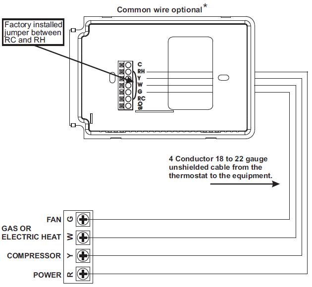
4 Wire, 1 Stage Cooling, 1 Stage Heating Residential Gas or Electric Heat, Electric Cool, split systems & package units. For jumper configuration see pages 18 and 19

4 Wire, 1 Stage Cooling, 1 Stage Heating-Heat Pump with O reversing valve. Residential Heat Pumps, split systems & package units, with no auxiliary heat. For jumper configuration see page 20.

4 Wire, 1 Stage Cooling, 1 Stage Heating-Heat Pump with B reversing valve. Residential Heat Pumps, split systems & package units, with no auxiliary heat. For jumper configuration see page 21.
3 Wire, 1 Stage Heating Residential Gas or Electric Heat units with a separately controlled fan. For jumper configuration see pages 18 and 19.

2 Wire, 1 Stage Gas Heat Residential Gas or Millivolt units. For jumper configuration see page 18
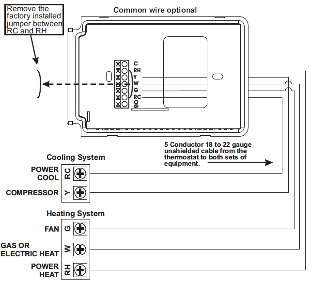
Dual Transformer 5 Wire, 1 Stage Cooling, 1 Stage Heating Residential Gas or Electric Heat, Electric Cool, split systems & package units. For jumper configuration see pages 18 and 19
Jumper Configuration
Cooling and Gas Heating
Residential Gas, Electric Cool, split systems & package units
| OUTPUTS | ||
| No Demand | With Demand | |
| Cooling Mode | O/B* | Y, G, O/B* |
| Heating Mode | O/B* | W, O/B* |
Cooling and Electric Heating
Residential Electric Heat units with a separately controlled fan.

| OUTPUTS | ||
| No Demand | With Demand | |
| Cooling Mode | O/B* | Y, G, O/B* |
| Heating Mode | O/B* | W, G, O/B* |
Cooling and Heating – Heat Pump with O reversing valve.
Residential Heat Pumps, split systems & package units, with no auxiliary heat.
| OUTPUTS | ||
| No Demand | With Demand | |
| Cooling Mode | O | Y, G, O |
| Heating Mode | – | Y , G |
Cooling and Heating – Heat Pump with B reversing valve.
Residential Heat Pumps, split systems & package units, with no auxiliary heat.

| OUTPUTS | ||
| No Demand | With Demand | |
| Cooling Mode | – | Y, G |
| Heating Mode | B | Y, G, B |
Test Operation
- Turn on the power to the Heating/air conditioning system.
- On the thermostat, slide the Mode Switch to HEAT. Press the COOLER or WARMER button until the set temperature is 10 degrees above room temperature.
- The HVAC unit should energize in the heating mode (Page 6). Note: You may need to wait up to five minutes for heating to energize due to the compressor lockout feature.
- On the thermostat, slide the Mode Switch to COOL. Press the COOLER or WARMER buttons until the set temperature is 10 degrees below room temperature. The
- HVAC unit should energize in the cooling mode (Page 6). Note: You may need to wait up to five minutes for cooling to energize due to the compressor lockout feature.
- On the thermostat, slide the Mode Switch to OFF. Slide the Fan Switch to Fan On. The fan should turn on and run continuously (Page 6).
Troubleshooting
- SYMPTOM: The air conditioning does not attempt to turn on.
- CAUSE: The compressor timer lockout may prevent the air conditioner from turning on for a period of time.
- REMEDY: Consult the Owner’s Manual in the Installer Setup section to defeat the Cycles Per Hour (page 26).
- SYMPTOM: The display is blank.
- CAUSE: Lack of proper power.
- REMEDY: Make sure the power is on to the furnace and that you have 24vac between R & C.
- SYMPTOM: The air conditioning does not attempt to turn on.
- CAUSE: The cooling setpoint is set too high.
- REMEDY: Lower the cooling setpoint or lower the cooling set-point limit. See Setpoint Limits (page 26).
- SYMPTOM: The heating does not attempt to turn on.
- CAUSE: The heating setpoint is set too low.
- REMEDY: Raise the heating setpoint or raise the heating set-point limit. See Setpoint Limits (page 26).
- SYMPTOM: When controlling a residential heat pump, and asking for cooling, the heat comes on.
- CAUSE: The thermostat reversing valve jumper is set for B.
- REMEDY: Set the reversing valve jumper for O.
- SYMPTOM: When calling for cooling, both the heat and cool come on.
- CAUSE: The thermostat equipment jumper is configured for HP and the HVAC unit is a Gas/Electric.
- REMEDY: Set the equipment jumper for Gas.
- SYMPTOM: When the Program button is pressed, the display reads “DISABLED”.
- CAUSE: Program mode is set to NON PROGRAM.
- REMEDY: Set Program Mode (Setup 1) to 1, 5/2, or 7 Day. See Selecting Your Program Mode
Warranty
One-Year Warranty – This Product is warranted to be free from defects in material and workmanship. If it appears within one year from the date of original installation, whether or not actual use begins on that date, that the product does not meet this warranty, a new or remanufactured part, at the manufacturer’s sole option to replace any defective part, will be provided without charge for the part itself provided the defective part is returned to the distributor through a qualified servicing dealer. THIS WARRANTY DOES NOT INCLUDE LABOR OR OTHER COSTS incurred for diagnosing, repairing, removing, installing, shipping, servicing or handling of either defective parts or replacement parts. Such costs may be covered by a separate warranty provided by the installer.
THIS WARRANTY APPLIES ONLY TO PRODUCTS IN THEIR ORIGINAL INSTALLATION LOCATION AND BECOMES VOID UPON REINSTALLATION.
LIMITATIONS OF WARRANTIES – ALL IMPLIED WARRANTIES (INCLUDING IMPLIED WARRANTIES OF FITNESS FOR A PARTICULAR PURPOSE AND MERCHANTABILITY) ARE HEREBY LIMITED IN DURATION TO THE PERIOD FOR WHICH THE LIMITED WARRANTY IS GIVEN. SOME STATES DO NOT ALLOW LIMITATIONS ON HOW LONG AN IMPLIED WARRANTY LASTS, SO THE ABOVE MAY NOT APPLY TO YOU. THE EXPRESSED WARRANTIES MADE IN THIS WARRANTY ARE EXCLUSIVE AND MAY NOT BE ALTERED, ENLARGED, OR CHANGED BY ANY DISTRIBUTOR, DEALER, OR OTHER PERSON WHATSOEVER.
ALL WORK UNDER THE TERMS OF THIS WARRANTY SHALL BE PERFORMED DURING NORMAL WORKING HOURS. ALL REPLACEMENT PARTS, WHETHER NEW OR REMANUFACTURED, ASSUME AS THEIR WARRANTY PERIOD ONLY THE REMAINING TIME PERIOD OF THIS WARRANTY.
THE MANUFACTURER WILL NOT BE RESPONSIBLE FOR:
- Normal maintenance as outlined in the installation and servicing instructions or owner’s manual, including filter cleaning and/or replacement and lubrication.
- Damage or repairs required as a consequence of faulty installation, misapplication, abuse, improper servicing, unauthorized alteration or improper operation.
- Failure to start due to voltage conditions, blown fuses, open circuit breakers or other damages due to the inadequacy or interruption of electrical service.
- Damage as a result of floods, winds, fires, lightning, accidents, corrosive environments or other conditions beyond the control of the Manufacturer.
- Parts not supplied or designated by the Manufacturer, or damages resulting from their use.
- Manufacturer products installed outside the continental U.S.A., Alaska, Hawaii, and Canada.
- Electricity or fuel costs or increases in electricity or fuel costs for any reason whatsoever including additional or unusual use of supplemental electric heat.
- ANY SPECIAL INDIRECT OR CONSEQUENTIAL PROPERTY OR COMMERCIAL DAMAGE OF ANY NATURE WHATSOEVER. Some states do not allow the exclusion of incidental or consequential damages, so the above may not apply to you.
REFERENCE:
DOWNLOAD MANUALS:
Source1 S1-THEC11NS Non-Programmable Thermostat Owners Manual

Source1 S1-THEC11NS Non-Programmable Thermostat Owners Manual