Source1 S1-TBPU435-S High-Resolution Digital Thermostat
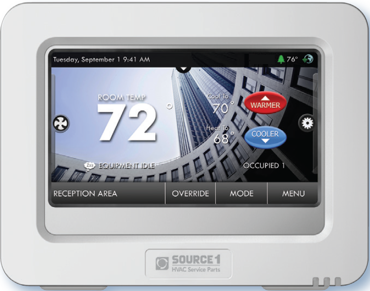
Get To Know Your Thermostat
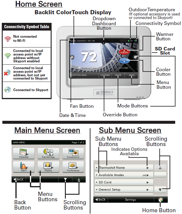
Dropdown Dashboard
(The contents of your Dashboard may vary)
- The Dropdown Dashboard displays temperature and other readings.
- It will also show the high and low readings of the day.
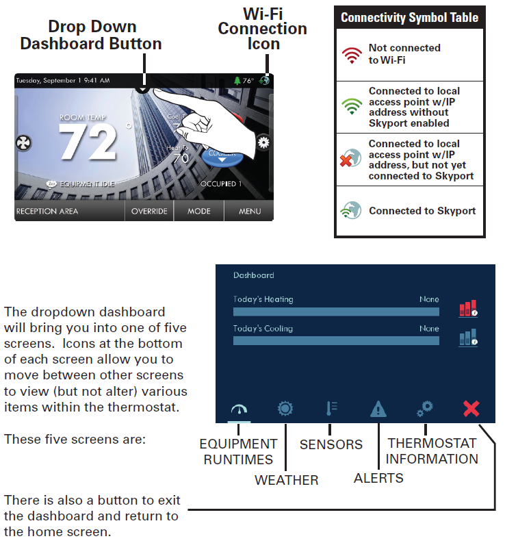
Equipment Runtimes
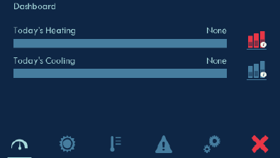
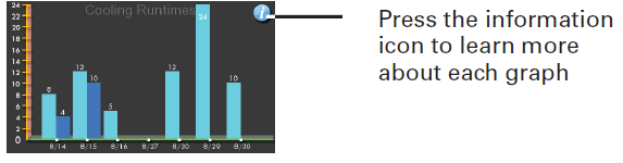
This screen allows you to view daily heating and cooling runtimes and can show details about which stages were active. To view one week of runtime data, press menu > information > view runtime graphs
Weather
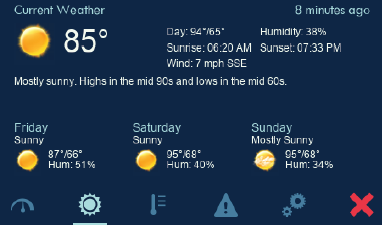 This screen only appears when the thermostat is communicating with Skyport. Current temperature/humidity and a 3 day forecast is shown based on the address details entered for the Skyport location that contains this thermostat.
Sensors
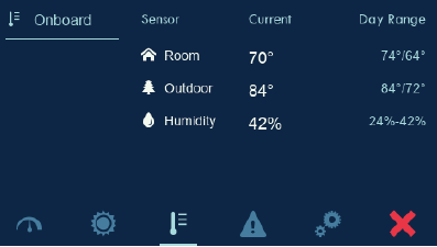
This screen shows values from the sensors inside of the thermostat, optional wired outdoor temperature sensor and paired wireless sensors. Daily min/ max are also shown (resets at midnight).
Alerts
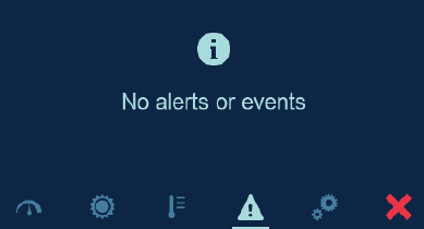
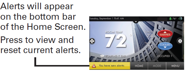
This screen shows some information about any active alerts. More information about alerts as well as resetting active alerts can be founds at menu > alerts.
Thermostat Information
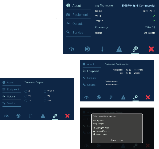
This section contains four different screens that allow easy viewing of the thermostat model number, firmware revision, Wi-Fi and Skyport status as well as DIP switch settings, active outputs and other items. Press on left side of screen to change between About, Equipment, Outputs and Service.
Care and Use of Your Thermostat
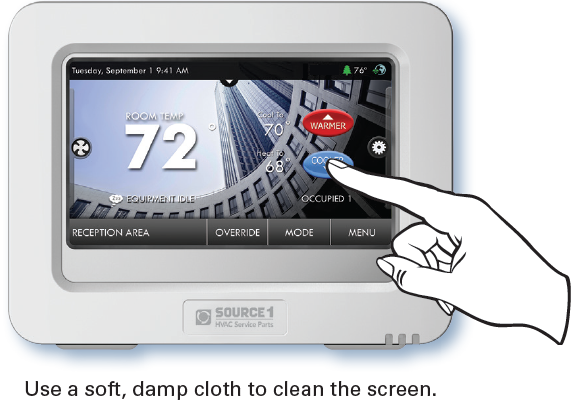
Pencils, pens and other sharp objects should never be used on your thermostat; these may damage your touch screen. Only use your fingertip to press the touchscreen buttons.
CAUTION: DO NOT USE ABRASIVE CLEANERS OR CLEANERS THAT CONTAIN SOLVENTS. DO NOT SPRAY ANYTHING DIRECTLY ONTO THE THERMOSTAT.
Quick Start
Temperature, Modes & Fan
Selecting Your Desired Temperature and Mode
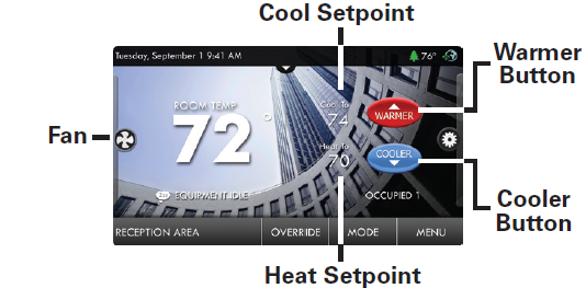
Press  to adjust temperature
The Heat or Cool Setpoint is the temperature the room has to reach before heating or cooling will turn on. (Without regard to deadband)
Press or the MODE Icon
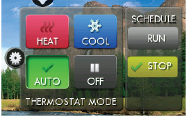
- HEAT will allow only heat operation.
- COOL will allow only cool operation.
- AUTO will allow both Heat and Cool operation.
- OFF – heating and cooling systems are turned off.
- AUTO-CHANGEOVER MODE – Pressing the WARMER or COOLER buttons in Automode will adjust both the heat and cool setpoints simultaneously. To adjust heat and cool setpoints individually, choose
- HEAT mode to adjust the heat setpoint and COOL mode to adjust the cool setpoint, then return to AUTO mode.
- HEAT OR COOL MODE – Pressing the WARMER or COOLER buttons in Heat or Cool mode will adjust only the heat or cool setpoints.
Press the FAN Icon
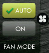
- FAN ON fan runs constantly except in OFF Mode.
- FAN AUTO fan only runs with a heating or cooling demand.
Note: The FAN button is disabled during Program Run Mode.
Override
Using the Override Button
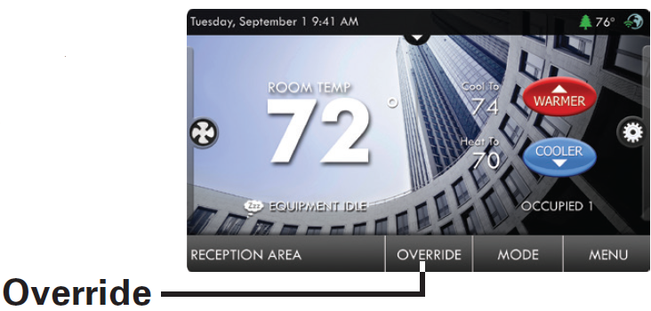
NOTE: Override may only be used when the thermostat is set to Program RUN or Holiday ON modes.
Unoccupied Operation: During programmed, unoccupied periods, pressing the OVERRIDE button will force the thermostat into Occupied 1 settings. When the OVERRIDE button is pressed, a timer screen will appear and allow the user to choose from 30 minutes to up to 4 hours of override time. To turn off the override timer, press the OVERRIDE button and when the timer screen appears, press CANCEL OVERRIDE.
Occupied Operation: During programmed, occupied periods, pressing the OVERRIDE button will force the thermostat into an unoccupied period for the rest of the day. During this forced unoccupied period the OVERRIDE button will operate as described above.
Holiday Operation: During Holiday Mode, pressing the OVERRIDE button will force the thermostat into the Occupied 1 settings. When the OVERRIDE button is pressed, a timer screen will appear and allow the user to choose from 30 minutes to up to 4 hours of override time. To turn off the override timer, press the OVERRIDE button and when the timer screen appears, press CANCEL OVERRIDE.
Set Time & Date
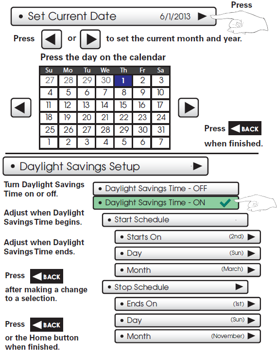
NOTE: When the thermostat is connected to a Skyport account, the Time & Date are automatically synchronized to the Skyport Cloud, including automatic Daylight Savings adjustments. Your time zone is selected in the Skyport web application.
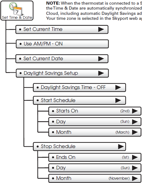
Setting the Time
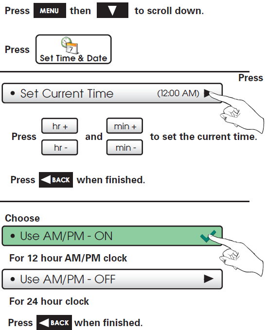
Setting the Date
Connect to Wi-Fi
Connect to Wi-Fi (from initial start-up)
When power is connected to the thermostat and it has not been configured to connect to a Wi-Fi Access point, the following message appears:
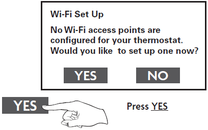
- Select the access point you wish to connect to from the list.

Enter the password for the Wi-Fi Access Point and press NEXT.
Select automatic setup and press NEXT.
When finished, a dialog box will appear confirming the successful connection to the local Wi-Fi Access Point.
Select OK, then the Wi-Fi status page will appear. Upon closing of the Wi-Fi status page, you will be asked to join the thermostat to a Skyport account.
Select YES and follow the onscreen instructions to create a new Skyport account or to add the thermostat to an existing account.
Connect to Wi-Fi (from menus)
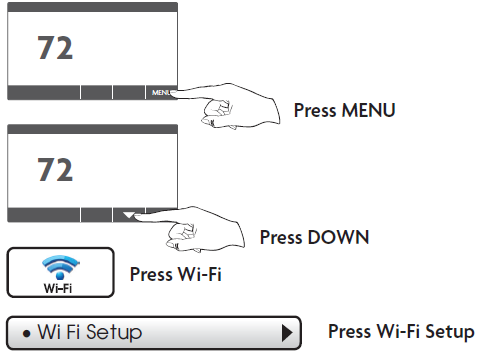
- Select the access point from the list that you want to connect to.
Enter the password for the Wi-Fi Access Point and press NEXT.
Select automatic setup and press NEXT.
When finished, a dialog box will appear confirming the successful connection to the local Wi-Fi Access Point.
Select OK, then the Wi-Fi status page will appear. Upon closing of the Wi-Fi status page, you will be asked to join the thermostat to a Skyport account.
Select YES and follow the onscreen instructions to create a new Skyport account or to add the thermostat to an existing account.
Although there is more than one way to create a Skyport account, the steps below illustrate creation from a browser. If the thermostat is connected to the local Wi-Fi Access Point, but not yet joined to a Skyport account, you may join the thermostat to an account by doing the following:
- Select MENU from the thermostat’s home screen.
Scroll down
Select Skyport
Select Skyport Account and follow the onscreen instructions.
- Open your browser to: https://Source1.skyportcloud.com
- Select “Create account now”

- Follow the onscreen instructions to create an account and add a thermostat to the Skyport account.
Schedule
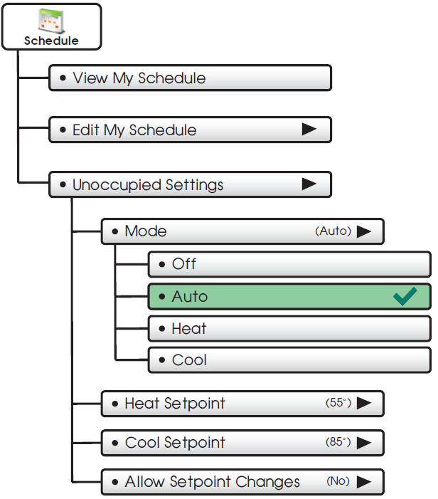
 This thermostat features up to 3 Occupied time periods per 24 hour day.

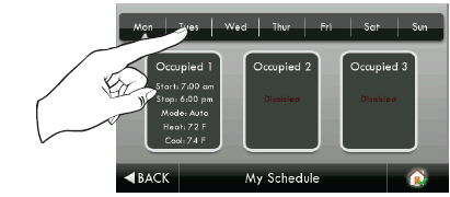
- Press a day of the week to view its settings. This may be repeated for each day.

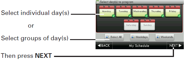
- Press and select day(s) to program
- Press and select a Time Period (Occupied 1, Occupied 2, or Occupied 3) to edit.
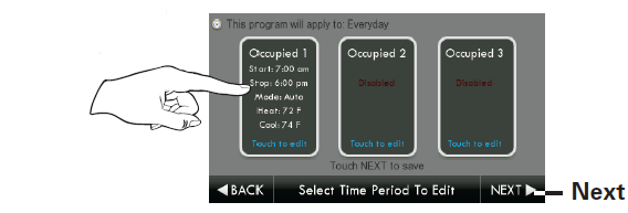
TIP: Occupied 2 will override Occupied 1, and Occupied 3 will override Occupied 1 & 2.
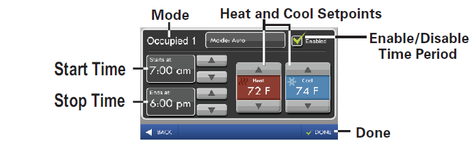
Adjust Mode, Start Time, Stop Time, and Heat and Cool Setpoin ts to desired settings. The Time Period May also be Enabled or Disabled. Un-check the enabled box for Time Periods you don’t want to use. Press DONE when finished.
When you are finished editing the time periods press
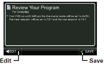
- Review your program.
- Press SAVE to keep your program.
- Press EDIT to make further changes.
Unoccupied Settings
Choose your Mode and Heat and Cool setpoints for the Unoccupied period.
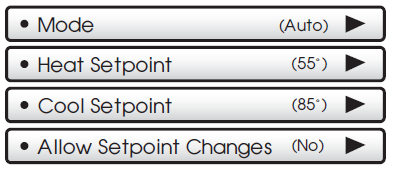
Press  or the MODE Icon
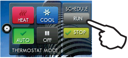
- On the H ome Screen to select to Run or Stop Schedule
Fan Settings
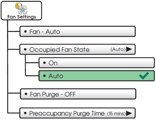
 The fan may be set to run continuously during Heat, Cool, Auto, and Occupied modes. A Preoccupancy Fan Purge schedule may also be set.
- Press to turn fan On to run continuously or Auto for fan to run only with heating or cooling.
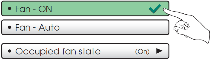
- Press to turn fan On to run continuously during Occupied mode or Auto for fan to run only with heating or cooling.
Fan Purge – OFF
- Press to turn on Preoccupancy Fan Purge. This feature allows the fan to run for a preset amount of time before Occupied 1 begins.
Preoccupancy Purge Time (15 mins)
- The Preoccupancy Fan Purge timer may be set from 15 minutes to 3 hours in 15 minute increments.
Screensaver
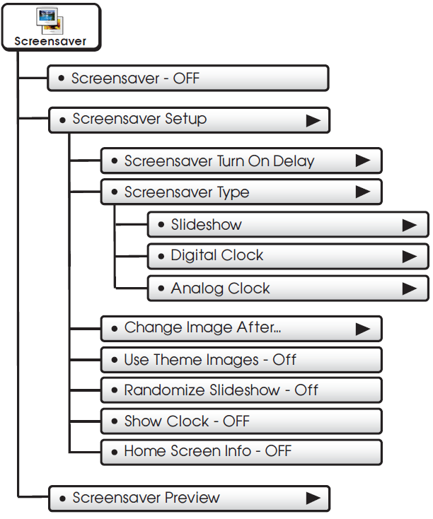
 The Screensaver allows you to create custom slideshows.
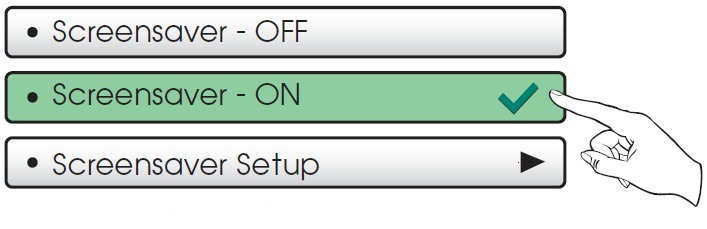
Screensaver Turn On Delay (5m)
How long after a button press for the Screensaver to appear. 1, 3, 5, or 30 minutes
Screensaver Type (Slideshow)
Slideshow, Digital Clock, Analog Clock
Change Image After…
15, 30 seconds – 1, 5, or 10 minutes
Use Theme Images – OFF
Slideshow uses included Theme Images. Off or On
Randomize Slideshow – OFF
Shuffles slideshow photos in random order
Show Clock – OFF
Shows the time and date every 5 photos. Off or On
Home Screen Info – OFF
Shows the mode, setpoints, and temperature after every 10 photos. Off or On.
Screensaver Preview
- Press this button to preview your screensaver operation before returning to the Home Screen.
- After the preview, press anywhere on the screen to return to the sub menu.
Alerts
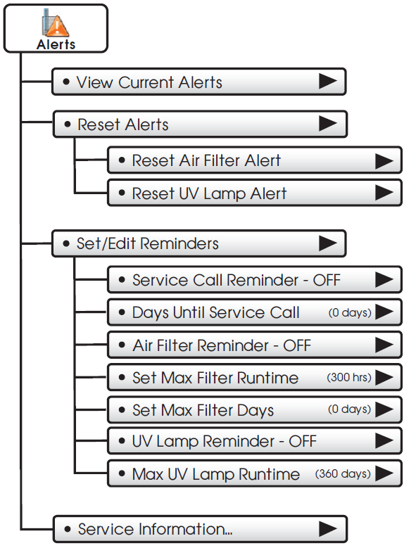
 The alerts let you know when your system needs service.
View Current Alerts
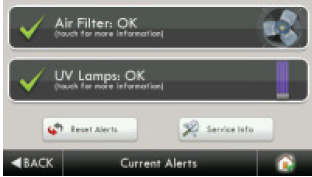
- View and reset current service alerts here.
Reset Alerts
- Clear and reset current service alerts.
Set/Edit Reminders
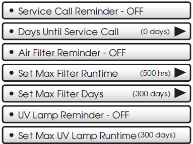
- Set service alert runtimes and turn reminders on or off.
Display
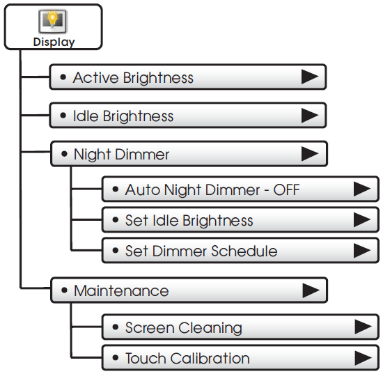
 The display brightness options may be adjusted in this menu.
Active Brightness (80%)
- You may select how bright the backlight is while the thermostat is active.
- The display is active for 3 minutes after last touch, it then goes Idle.
Idle Brightness (30%)
- You may select how bright the backlight is while the thermostat is idle.
Night Dimmer
- You may dim the brightness of the screen at night.
Auto Night Dimmer – OFF
- The screen can be set to dim automatically at night.
- Dimming the display can prolong the life of the backlight.
Set Idle Brightness (50%)
- Set the screen brightness for the Night Dimmer. When Night Dimmer is On, the display will go idle 8 seconds after last touch.
Set Dimmer Schedule
- Set the schedule for the Night Dimmer.
Maintenance
- Maintenance allows you to clean and calibrate the touch screen.
Screen Cleaning
- Screen Cleaning Mode disables the touch feature for 15 seconds so the screen may be cleaned without altering any settings.
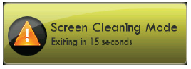
- Use a soft cloth without solvents or abrasive cleaners.
Touch Calibration
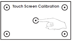
- Under normal circumstances, the touchscreen should not need to be calibrated.
- Touch and hold the center of the targets as they appear on the screen for 3 seconds.
Press FINISH when done.
- When calibration is complete, the thermostat will automatically restart and return to the Home Screen.
Preferences
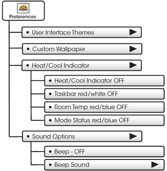
 You may set the type of background that appears on the thermostat Home Screen.
User Interface Themes (ocean)
- This thermostat has several high quality background themes to choose from.
NOTE: At 7pm, the background will change to an evening scene. At 7am it will return to a daytime scene.
Custom Wallpaper
- You may choose your own background image by selecting a photo that you have uploaded from an SD memory card.
Heat/Cool Indicator
You may choose an enhanced indicator of the current status of the HVAC equipment.
- Heat/Cool Indicator – ON/OFF
- Taskbar Red/White – ON/OFF
- Room Temp Red/Blue – ON/OFF
- Mode Status Red/Blue – ON/OFF
Sound Options
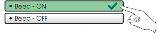
- Turn the beep sound on or off.
Beep Sound (Beep 1)
- Choose from different beep sounds.
Holidays
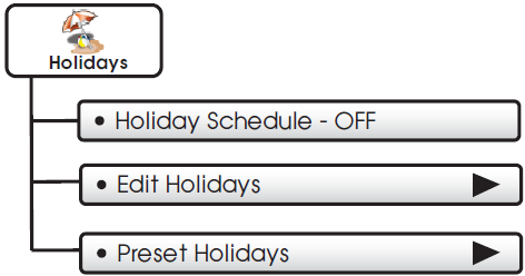
 The Holiday Schedule allows the thermostat to follow a fully customizable preset, weekly, monthly, and yearly holiday program. The thermostat will stay in Unoccupied settings while Holiday is active.
Holiday Schedule – OFF
- Press to turn Holiday Schedule On or Off.
Edit Holidays
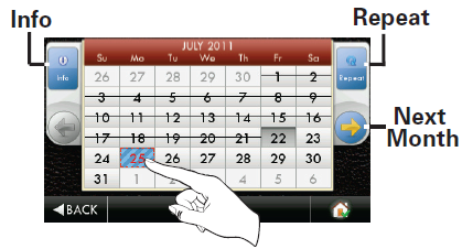
- Start by selecting a Holiday.
- You may continue to select more holidays or you can press the Repeat button for recurring holidays.
- Pressing a selected holiday will deselect that holiday.
Using the Repeat Button
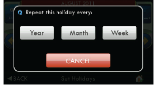
- Choose to repeat the holiday every week, month or year. Or, press CANCEL to go back.
- If you choose to repeat the holiday every week, you will be prompted to confirm the day of the week to be repeated.
Using the Info Button
- Press the Info button to view how non-holidays, holidays, and exceptions to repeating holidays will appear on the Holiday calendar.
Deselecting Holidays
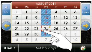
- You may deselect a holiday simply by pressing on it.
- Press BACK to save your changes and return to the Holiday menu.
- If you choose to deselect a holiday that is part of a Custom Repeating Program, the screen below will appear.
Marking Non-Holidays
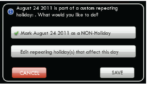
- You will now be prompted to mark this day only as a non-holiday or edit All repeating holidays that affect this day.
- Press SAVE to mark only this day as a non-holiday.
- If you choose to edit repeating holidays that affect this day, press NEXT and the next screen will appear.
Editing Repeating Holidays
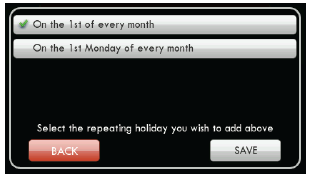
If, for example, you choose to repeat the holiday every month, the following screen will appear:
You may now choose to repeat the holiday:
- On the 24th of every month
- On the 4th Wednesday of every month
- On the last Wednesday of every month
Press SAVE to save your changes and return to Holiday programming.
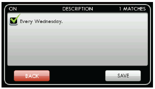
- You may now delete all repeating custom holidays in this group by pressing the ON box to uncheck your selection. Press SAVE to return to Holiday editing screens.
Preset Holidays
- You may choose from several standard preset holidays to observe.
- When the preset holidays are set to ON, they will be observed every year on that date.
Overriding Holiday Mode
- You may override Holiday Mode by pressing the OVERRIDE button and choosing the amount of override time desired.
Turning Off Holiday Mode From The Homescreen
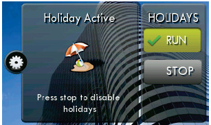
- You may turn off Holiday Mode by pressing the MODE button and then pressing the Holiday STOP button.
Security
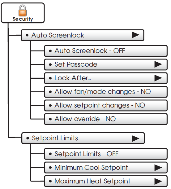
 Security settings may be set to limit or prevent changes to your thermostat.
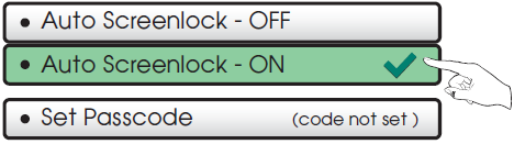
Auto Screenlock
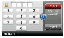
Use keypad to enter and confirm passcode.
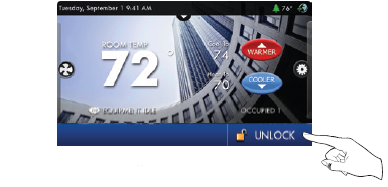
- When the thermostat is locked, the bottom bar of the display will show:

NOTE: Code must be set before Auto Screenlock can be turned on.
Press UNLOCK then enter the passcode to access thermostat settings.
Lock After… (5 m)
Set the time the screen will automatically lock after the last button press.
Allow fan/mode changes – NO
Choose to allow mode changes when Auto Screenlock is on.
Allow setpoint changes – NO
Choose to allow setpoint changes when Auto Screenlock is on.
Allow override – NO
Choose to allow use of the Override button when Auto Screenlock is on.
Setpoint Limits
Limits how high or low heating and cooling may be adjusted.
Information
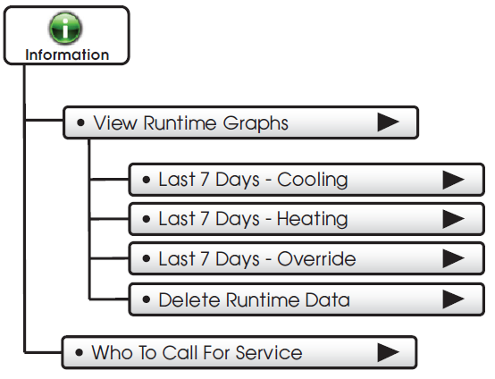
 This button contains valuable service and system runtime information.
View Runtime Graphs
- Track your system’s runtime/energy usage.
Last 7 Days – Cooling
Last 7 Days – Heating
NOTE: The runtime graphs are updated at 12:00 AM each day.
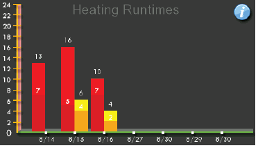
- Press anywhere on the screen to return to the submenu.
Last 7 Days – Override
- Press to view a graph of override runtime information.
Delete Runtime Data
- Press to delete your current equipment runtime information.
Who To Call For Service
- Your service company’s contact information is displayed here.
Settings
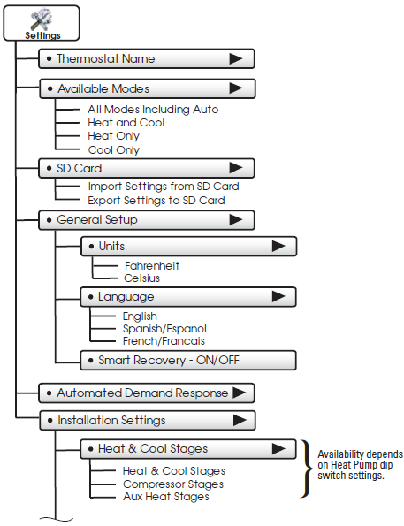
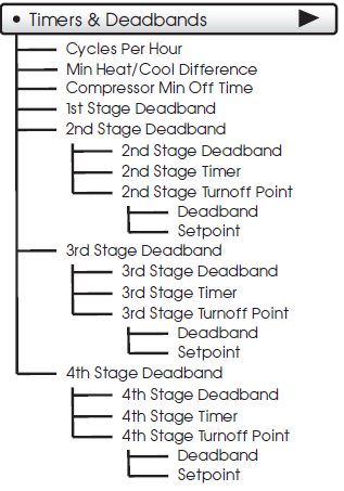
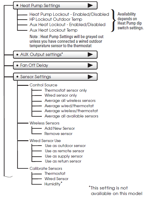
 Thermostat heating and cooling options are found in this menu
Thermostat Name
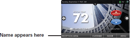
- Use keypad to name your thermostat. The name is displayed on the Home Screen.
(Up to 14 characters)
Available Modes (all)
Choose the desired modes the thermostat will use: Heat, Cool, Heat & Cool, or Auto (All). For example, if you only have a heater, choose Heat, and only Heat & Off modes will be available. This will simplify the operation for the user.
SD Card
- Import and export files to and from the thermostat. See the CTS Desktop App instructions for further details.
Import Settings from SD Card
- Upload files from CTS Desktop App or another thermostat.
NOTE: A 2GB SD card is recommended. To import and export files, the SD card must contain the same version of the firmware as the thermostat. CTS Desktop App will keep the firmware current.
Export Settings to SD Card
- Export files from one thermostat and import them into others.
General Setup
Units (F)
- Fahrenheit (F)
- Celsius (C)
Language (en)
- English
- Spanish/Español
- French/Français

Smart Recovery turns on the heat or cool before the Occupied start time to bring the room temperature to the Occupied setpoint at the start of the Occupied time period. Please allow 4-8 days for Smart Recovery time to adjust. When used with a heat pump, electric strip heat will be disabled while Smart Recovery is active.
Automated Demand Response Overview
Touch Screen thermostats support the handling of specific signals from the utility provider. The utility-generated signals carry pricing information and/or setback actions that alter the comfort settings of the thermostat in order to reduce energy usage on demand. This is known as Automated Demand Response or ADR for short. You must register to participate in a utility-sponsored program, if offered by your local utility, to take advantage of this feature.
SKYPORT CLOUD SERVICES
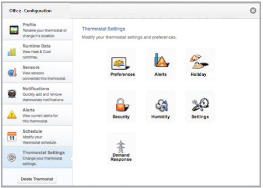
- From the web application the user will select Thermostat Settings from the left column. Then the Demand Response button is selected.
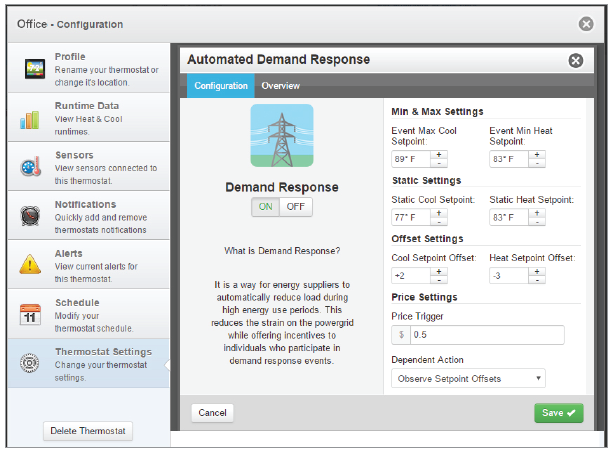
The Demand Response configuration page, shown below, is where the thermostat is configured to respond to the energy provider’s signals. It also sets operational parameters for the thermostat. The left column of the ADR configuration page allows or prevents access by the utility. Here communication with the utility and your thermostat may be turned On or Off.
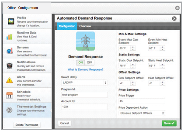
The right column of the ADR configuration page is where the occupant adjusts the operational parameters for ADR. The utility may send up to 3 types of ADR signals to Skyport. These are:
- Pricing for the cost of energy,
- An Offset to the occupants’ comfort setpoints
- a signal to enforce discrete or Staticsetpoints.
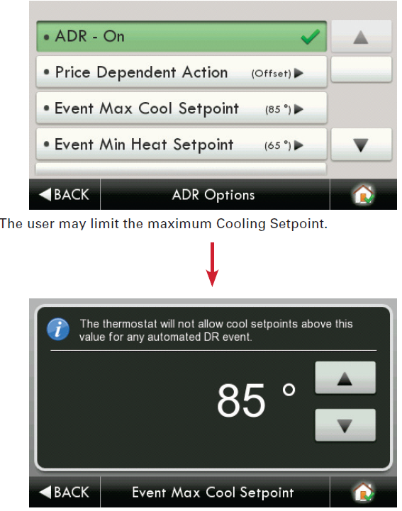
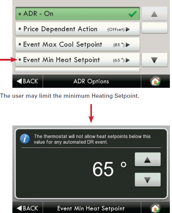
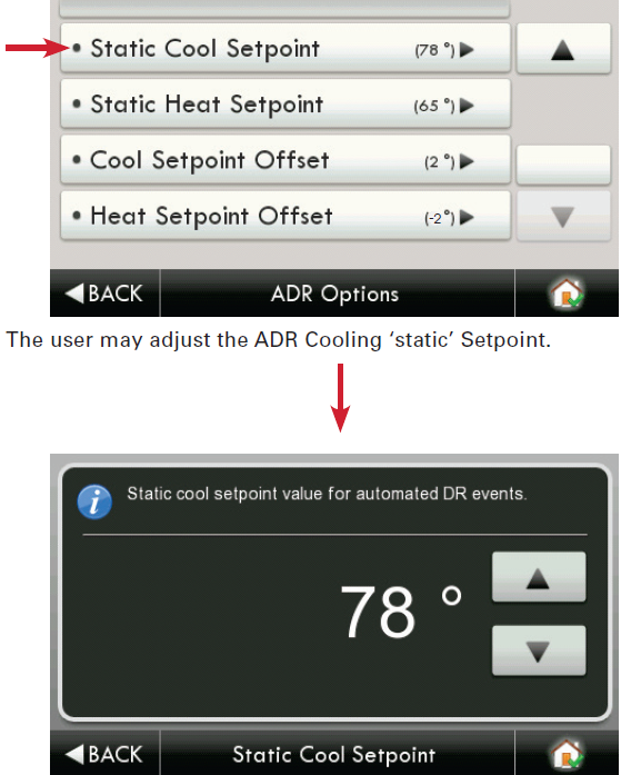
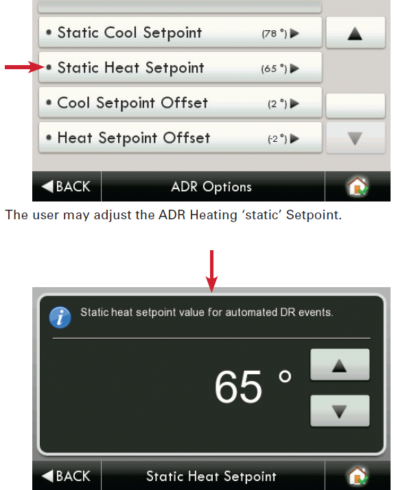
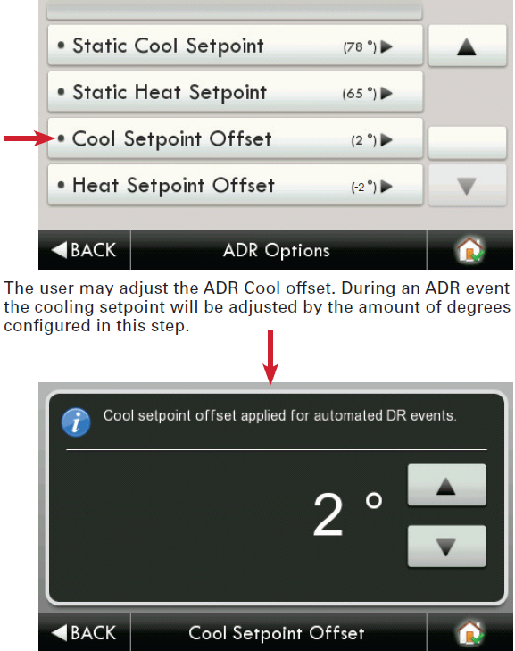
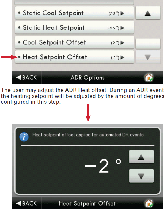
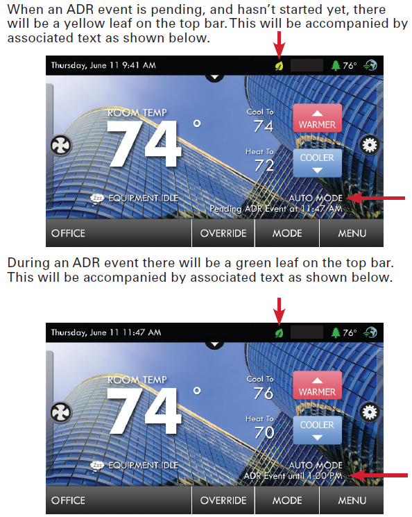
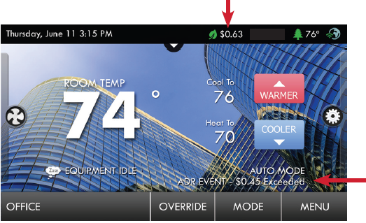
The Maximum Cooling Setpoint and Minimum Heating Setpoints for ADR events are adjusted here. The Static Settings are applied when the utility sends a signal to allow the occupant to enforce their own discrete temperature settings during an ADR event. The Offset Settings allow the utility to modify the Cool or Heat setpoints by the value set here during an ADR event. A Price Trigger setting allows the occupant to set the maximum cost of energy threshold. When this threshold is exceeded the Price dependent action is enforced. This Price Trigger and Dependent action is enforced independent of an ADR event, as long as the utility sends ‘real-time’ pricing.
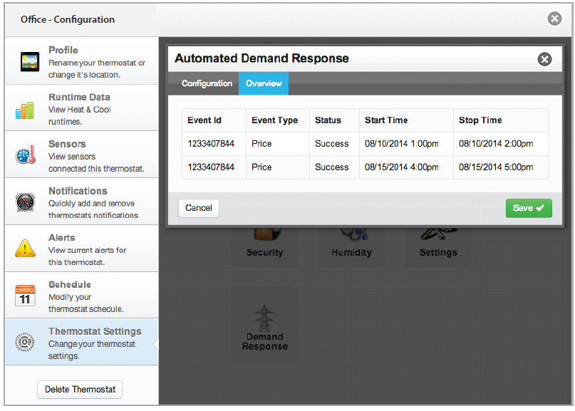
Selecting the Overview tab of the ADR page will cause a summary of ADR events to be displayed.
Automated Demand Response
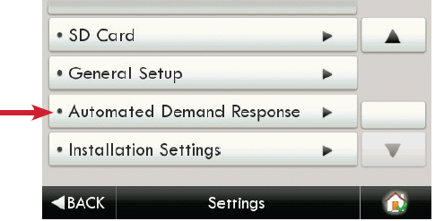
- Utility and Program setup must be done at the Skyport Cloud Services account. From the thermostat Home Screen, press the ‘Menu’ button, then select ‘Settings”.
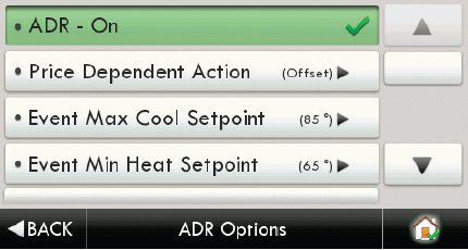
- From the above screen the ‘Automated Demand Response’ button is pressed.
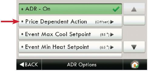
- Selecting the ‘Price Dependent Action’ button allows the user to determine what action is taken when the price rises above the set threshold.
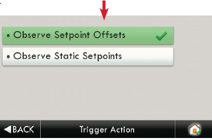
- In the above example; if the price threshold is exceeded, the thermostat will invoke the ‘Offset Setpoints’ configured for an ADR event until the event is over.
- Please note that the Threshold price may only be set in the Skyport Cloud Services account.
- Selecting ‘Skip Event’ will take no action when the set price threshold is exceeded.
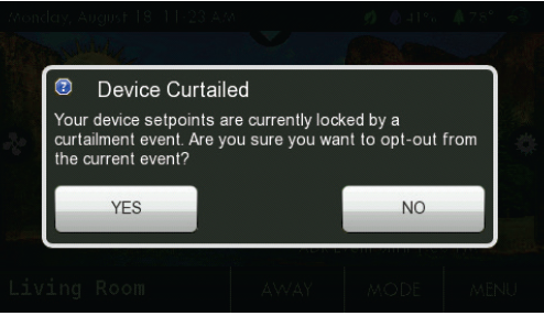
- If a Warmer or Cooler button is pressed during an active ADR event, then the user is presented with this opt-out screen.
Installation Settings
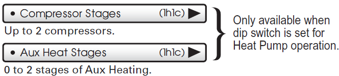
Heat & Cool Stages (1h1c)
Heat & Cool Stages (1h1c)
- Up to 2 Stages of Cooling and 4 stages Heating.
Timers & Deadbands
Cycles Per Hour (6)
- At 6 cycles per hour, the HVAC unit will only be allowed to energize once every 10 minutes. The Cycles Per Hour limit may be overridden and reset by pressing the WARMER or COOLER buttons. (2, 3, 4, 5, 6, No Limit)
Min Heat/Cool Difference (2°)
- The minimum gap between Heat and Cool setpoints. (0 – 6 deg. F)
Compressor Min OFF Time (5m)
- None, 3 minutes, or 5 minutes.
The Deadband is the number of degrees or minutes that the thermostat waits before it initiates the stages of heating or cooling. 1st Stage Deadband Specifies the minimum temperature difference between the room temperature and the desired setpoint before the first stage of heating or cooling is allowed to turn on. For example, if the heat setpoint is 68° and the 1st Stage deadband is set to 2 degrees, the room temperature will need to drop to 66 degrees before the heat turns on.
1st Stage Deadband (2°)
- (1 – 6 deg. F)
2nd Stage Deadband
2nd Stage Deadband (2°)
- Number of degrees past 1st stage before 2nd stage turns on. (0 – 10 deg. F)
2nd Stage Timer (2mins )
- The number of minutes past 1st stage before 2nd stage turns on. (0 – 60 mins.) (The 2nd stage deadband must also be met)
2nd Stage Turnoff Point (Deadband )
- Deadband or Setpoint.

(Only available when dip switch is set for Heat Pump operation AND you have a wired outdoor temperature sensor connected to the thermostat)
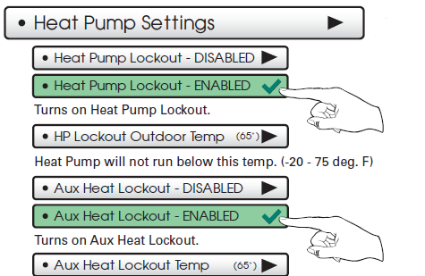
- Aux Heat will not run above this temp. (0 – 75 deg. F) GAS/EL or HP dip switch must be set for HP and GAS or ELEC dip switch must be set for ELEC.

Fan Off Delay (0s)
- Runs the fan for a short time after Cooling or electric strip heat turns off to increase system efficiency. (0 – 120 Secs.)
Sensor Settings
Control Sensor (thermostat )
When a remote sensor is connected to the thermostat, the user may choose which sensor source is used to measure room temperature.
- Thermostat sensor only
- Remote Sensor only
- Average remote/thermostat
Wired Sensor Use (remote)
The wired sensor may be used as follows:
- Outdoor sensor
- Remote Sensor
- Supply Sensor
- Return Sensor
Calibrate Sensors (0°)
- The thermostat and wired sensor may be calibrated -7 to +7 degrees F.
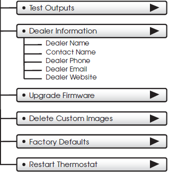
Test Outputs
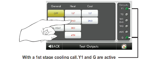
- The installer or service technician can use this feature to test the functions without any time delays of the thermostat.
Dealer Information
A Dealer may enter their company contact information for the customer to use when they need service. This will appear when the “Who To Call For Service” button is pressed in the Information Menu. Use the keyboard to enter your information.
- Dealer Name
- Contact Name
- Dealer Phone
- Dealer Email
- Dealer Website
Upgrade Firmware
Press to upgrade the thermostat firmware. The SD Card must be in the thermostat SD Card reader and contain the valid firmware. If you are connected to Skyport Wi-Fi and you receive an Alert that new firmware is available, simply press the Upgrade Firmware button to upgrade wirelessly.
Note: Occasionally an update that requires a large amount of data is not possible to do wirelessly. In this case an update using an SD card will be required.
Delete Custom Images
- Press to delete the custom photos you uploaded to the thermostat.
Factory Defaults
- Press to reset the thermostat back to the factory settings.
Restart Thermostat
- If needed, press here to restart the thermostat.
Wi-Fi
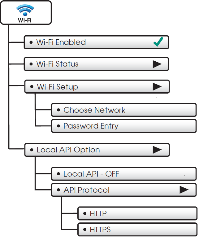
Wi-Fi Enabled
- Press to enable/disable Wi-Fi connectivity
Wi-Fi Status
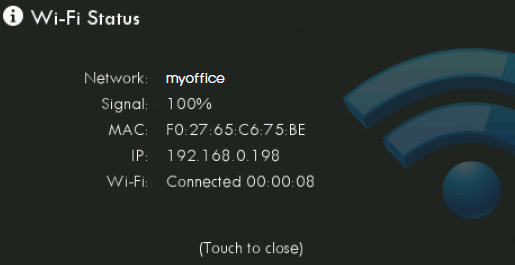
- It is here that you will find helpful information regarding the connectivity status of your thermostat, including the thermostat’s ID.
Wi-Fi Setup
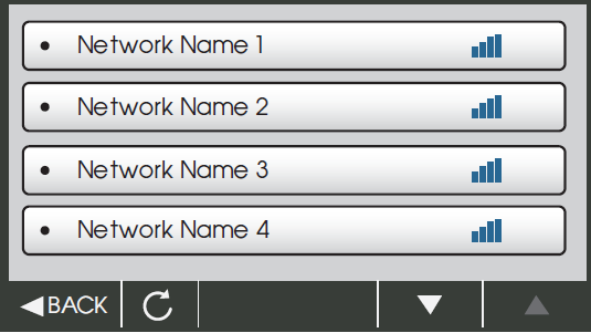
- Choose your network from the list and enter the network password.
 If your network does not appear in the list, hit the refresh button.
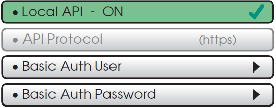
Local API Option
- Turning on the local API allows 3rd party software to interface with your thermostat, such as a home automation system.
- This is the default with the local API OFF.
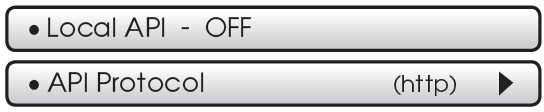
To turn on the HTTP Local API select Local API

- Press BACK to return to previous screen.
If a Secure API is required, then select API Protocol

- Upon pressing API Protocol, the following screen will appear.
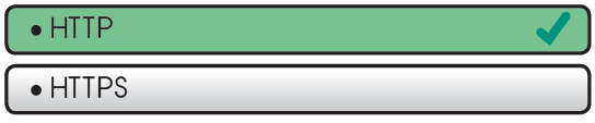
- Then select HTTPS and press BACK
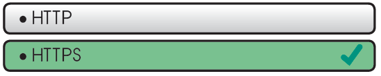
- Upon pressing BACK, the screen will look like this.
Basic Auth User
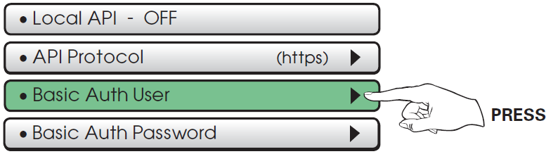
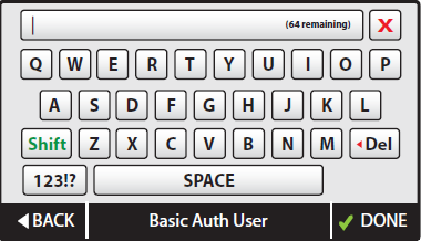
- Select Basic Auth User, and enter the appropriate information on the screen below and press DONE to save.
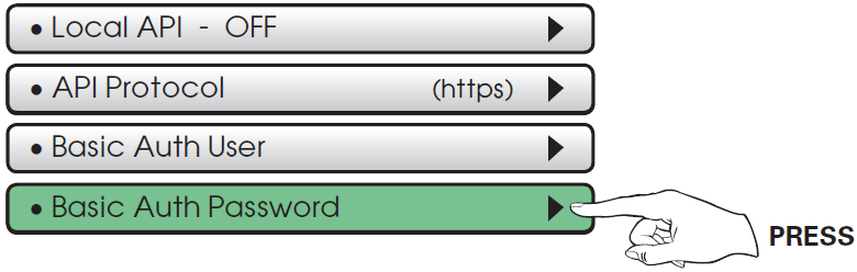
- Select Basic Auth Password as the next step.
Basic Auth Password
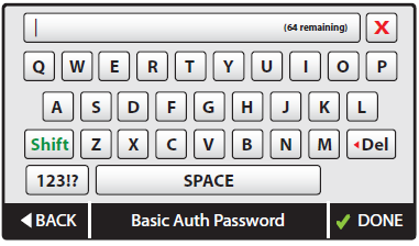
- Select Basic Auth Password and enter the appropriate information on the screen below and press DONE to save.
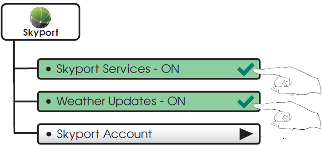
- The last step is to turn the Local API on as shown below.
Skyport
Skyport Account
- Pressing this button will let you know if you are paired with a Skyport account. If not, then you may follow prompt and instructions to create an account and add the thermostat to the account.
Emergency Heat
 The Emergency Heat function is only available if your thermostat is set to control a Heat Pump.
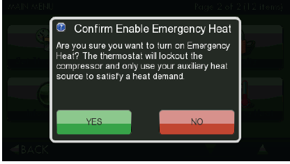
To initiate the Emergency Heat feature, Press the Emergency Heat button. During Emergency Heat operation the thermostat will turn on the fan and auxiliary stages of heat when there is a demand for heat. The 1st stage of heating and all stages of cooling will be unavailable. To exit Emergency Heat, press the Emergency Heat button.
CTS Series Desktop App
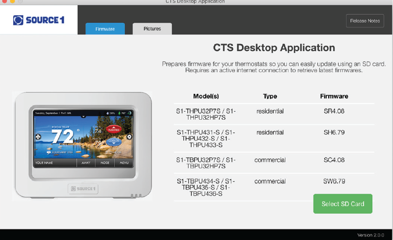
CTS Series Desktop App may be downloaded at no charge at: http://source1thermostats.com/CTSSeries.html#desktopApp
Every time the user runs the CTS Desktop App software, it automatically connects to the Source 1 Color Display website in the background and updates the software and firmware (the operating system for touch screen) at no cost.
The CTS Series Desktop App allows you to use your computer to:
- Upload photos for background and slideshow images
- An alternative method to update thermostat firmware
Uploading Photos and Settings to your thermostat
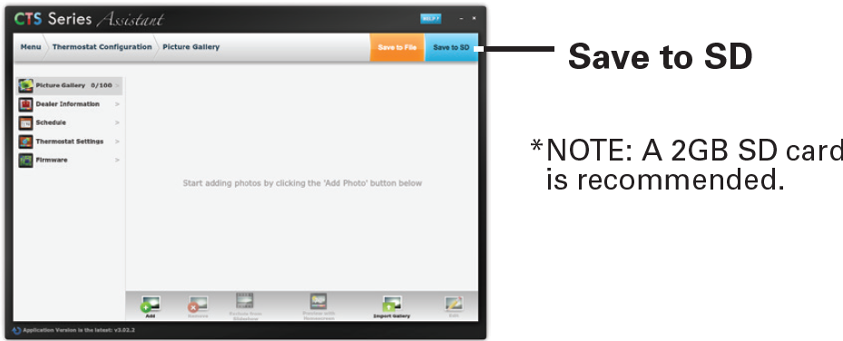
When you are finished adding and editing photos and settings, click on Save to SD. When prompted, remove the SD card from the SD card reader on your computer.
NOTE: A 2GB SD card is recommended.
At the thermostat
Insert the SD card into the SD Card Slot.
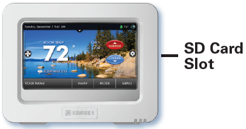
- Press
 then
then
- Next, press
- Press

- Then press

Select the items to import into your thermostat then press
Your thermostat will automatically save your new photos and settings in it’s internal memory. When finished, you may remove the SD card. It is not needed for normal thermostat operation.
Installation Instructions
Remove and Replace the old thermostat
To install the thermostat properly, please follow these step by step instructions. If you are unsure about any of these steps, call a qualified technician for assistance.
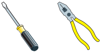
- Assemble tools: Flat blade screwdriver, wire cutters and wire strippers.
- Make sure your Heater/Air Conditioner is working properly before beginning installation of the thermostat.
- Carefully unpack the thermostat. Save the screws, any brackets, and instructions.
- Turn off the power to the Heating/Air Conditioning system at the main fuse panel. Most systems have a separate breaker for disconnecting power to the furnace.
- Remove the cover of the old thermostat. If it does not come off easily, check for screws.
- Loosen the screws holding the thermostat base or subbase to the wall and lift away.
- If you have a smart phone handy, take a photo of the wiring for future reference.
- Disconnect the wires from the old thermostat. Tape the ends of the wires as you disconnect them, and mark them with the letter of the terminal for easy re-connection to the new thermostat.
- Keep the old thermostat for reference purposes, until your new thermostat is functioning properly.
Wire Connections
If the terminal designations on your old thermostat do not match those on the new thermostat, refer to the chart below or the wiring diagrams that follow.
| Wire from the old thermostat terminal marked |
Function |
Install on the new thermostat connector marked |
| G or F | Fan | G |
| Y1, Y | Cooling | Y1 |
| W1, W | Heating | W1/0/B |
| Rh, R, M, Vr, A | Power | R |
| C | Common | C |
| O/B | Rev. Valve | W1/O/B* |
| W2 | 2nd Stage Heat | W2 |
| Y2 | 2nd Stage Cooling | Y2 |
| W3 | 3rd Stage Heat | W3 |
| OUT – | Outdoor Sensor | SENSOR |
| OUT + | Outdoor Sensor | SENSOR |
* O/B is used if your system is a Heat Pump.
Before you go any further, determine what your existing wiring and equipment situation is.
- If you have a Heating only system without Air Conditioning, the Source 1 thermostat will require 3 wires: R (24Vac), C (24Vac) and W (Heat). Most systems that only have Heating use very simple thermostats that require 2 wires: the R (24Vac) and W (Heat). The Source 1 thermostat requires 3 wires to the thermostat. In this case an Add-a-Wire accessory will not work and it will be necessary to install another wire for the C (24Vac) connection.
- If you have a single stage fossil fuel heater with air conditioning, the Source 1 model will require 5 wires for independent fan control. They are R (24Vac), C (24Vac), W (Heat), Y (Cooling), and G (Fan). You may connect only 4 wires, as instructed in the “Making 4 Wires Work When 5 Wires Are Required” section on page 75. If there are only 4 wires present that are connected to the existing thermostat, there are at least 3 options available to connect the Source 1 thermostat:
- Use the 4 wires as instructed in the“Making 4 Wires Work When 5 Wires Are Required” section on page 75, and note that the fan will only operate with a Heating or Cooling demand.
- Pull new thermostat wire from the HVAC equipment to the thermostat so that there are at least 5 wires available.
- Purchase and install a Source 1 Add-A-Wire accessory.
- If you have a multi-stage HVAC system comprised of a fossil fuel heater with air conditioning, the Source 1 thermostat will require the 5 wires mentioned above (R, C, W, Y, G) plus an additional wire for each additional stage of Heating or Cooling. You may reduce the 5 wire requirement to 4 if you give up independent fan control following the instruction in the “Making 4 Wires Work When 5 Wires Are Required” section on page 75, or use the optional Add-A-Wire accessory.
- If you have a heat pump without aux heat, the Source 1 model will require 5 wires: R (24Vac), C (24Vac), W1/O/B (Reversing Value), Y (1st Stage Compressor), and G (Fan). If you are short 1 wire, there are at least 3 options available to connect the Source 1 thermostat:
- Use the available wires as instructed in the“Making 4 Wires Work When 5 Wires Are Required” section on page 75 and note that the fan will only operate with a Heating or Cooling demand.
- Pull new thermostat wire from the HVAC equipment to the thermostat so that there are at least 5 wires available.
- Purchase and install a Source 1 Add-A-Wire accessory.
- If you have a heat pump with aux heat, the Source 1 model will require 6 wires: R (24Vac), C (24Vac), W1/O/B (Reversing Value), Y (1st Stage Compressor), W2 (Aux Heat), and G (Fan). If you are short 1 wire, there are at least 3 options available to connect the Source 1 thermostat:
- Use the available wires as instructed in the“Making 5 Wires Work When 6 Wires Are Required” section on page 76 and note that the fan will only operate with a Heating or Cooling demand.
- Pull new thermostat wire from the HVAC equipment to the thermostat so that there are at least 6 wires available.
- Purchase and install a Source 1 Add-A-Wire accessory.
Making 4 Wires Work When 5 Wires Are Required
If you would like to install the Source 1 thermostat using only 4 wires when 5 are required, follow the directions below. You will need a screwdriver along with a 3″ long piece of thermostat wire to use as a jumper:
- Make sure the power is off.
- Label and disconnect wires at the thermostat. Please note the color and corresponding wire designator with each color. For example: The R wire is red and the W wire is white and so on. You will need this information handy for the next step at the HVAC equipment.
- At the HVAC equipment end of the thermostat wires (usually at the furnace), locate the terminals that the wires are attached to.
- Remove the “G wire” from the terminal marked G.
- Place the “G wire” on terminal C.
- Place one end of the 3″ long jumper on terminal G.
- Place the other end of the 3″ long jumper on terminal Y. Please note that there will be more than 1 wire on terminal Y.
- When connecting the wires to the Source 1 thermostat, note that the wire that was previously connected to the G terminal of the old thermostat will now be required to be connected to the C terminal on the Source 1 thermostat. All other wires will be connected suchthat the connections on each end of the individual wires match terminal designations. For example: Connect the yellow wire on the thermostat end to the Y terminal on the thermostat. The yellow wire will be connected to the Y terminal on the HVAC equipment end also.
Making 5 Wires Work When 6 Wires Are Required
If you have a system that requires 6 wires, and you would like to install the Source 1 thermostat using only 5 wires, follow the directions below. You will need a screwdriver along with a 3″ long piece of thermostat wire to use as a jumper:
- Make sure the power is off.
- Label and disconnect wires at the thermostat. Please note the color and corresponding wire designator with each color. For example: The R wire is red and the W wire is white and so on. You will need this information handy for the next step at the HVAC equipment.
- At the HVAC equipment end of the thermostat wires (usually at the furnace), locate the terminals that the wires are attached to.
- Remove the “G wire” from the terminal marked G.
- Place the “G wire” on terminal C.
- Place one end of the 3″ long jumper on terminal G.
- Place the other end of the 3″ long jumper on terminal Y. Please note that there will be more than 1 wire on terminal Y.
- When connecting the wires to the Source 1 thermostat, note that the wire that was previously connected to the G terminal of the old thermostat will now be required to be connected to the C terminal on the Source 1 thermostat. All other wires will be connected such that the connections on each end of the individual wires match terminal designations. For example: Connect the yellow wire on the thermostat end to the Y terminal on the thermostat. The yellow wire will be connected to the Y terminal on the HVAC equipment end also.
The Source 1 Thermostat Backplate
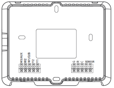
NOTE: The backplate does not fully cover a full size vertical junction box. The S1-CTSPLATE Source 1 Wallplate or a single-gang, horizontally mounted junction box would be needed for that type of installation.
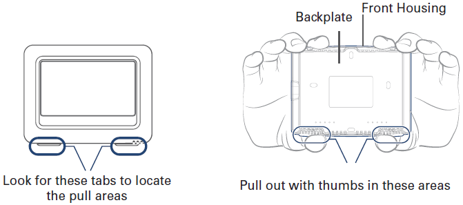
To remove the thermostat backplate: Using the Finger Pull Areas, pull the front housing away from the backplate.
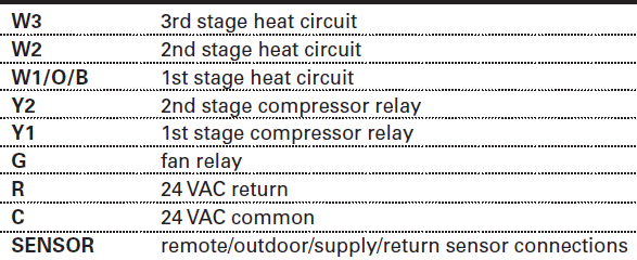
IMPORTANT: This thermostat requires both R (24 VAC Return) and C (24 VAC Common) be connected to the backplate terminals.
Explanation of Thermostat Dip Switches
Dip switches are located on the back of the thermostat
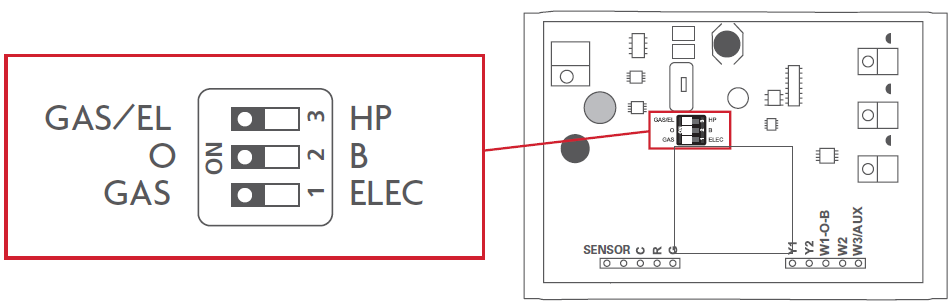
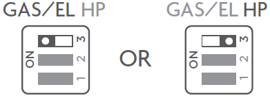
 This dip switch configures the thermostat to control a conventional gas/electric system or a heat pump. If your system is anything other than a heat pump, leave this switch set for GAS/EL.*
- For some commercial heat pumps, this switch may need to be set for GAS/EL. Consult the commercial heat pump literature.
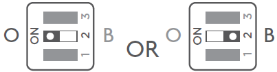
 When the GAS/EL or HP dip switch is configured for HP, this dip switch (O or B) must be set to control the appropriate reversing valve. If O is chosen, the W1/O/B terminal will energize in cooling. If B is chosen, the W1/O/B terminal will energize in heating.
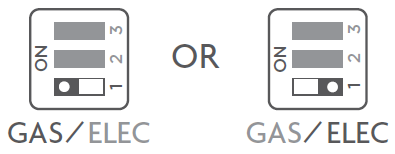 When GAS/EL or HP is set for GAS/EL: This switch (GAS or ELEC) controls how the thermostat will control the Fan (G) terminal in heating mode. When GAS is chosen, the thermostat will not energize the Fan (G) terminal in heating. When ELEC is chosen the thermostat will energize the fan in heating.
- When GAS/EL or HP is set for HP: This switch (GAS or ELEC) defines the Aux Heat type. When GAS is chosen, the auxiliary heat will not be allowed to run during heat pump operation. When using a Dual Fuel system, set this switch for GAS. When ELEC is chosen, up to two stages of auxiliary strip heat will be allowed to run.
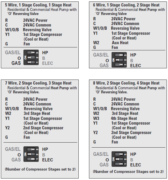
Sample Wiring Diagrams with Dip Switch Positions
Conventional Heating and Cooling Systems
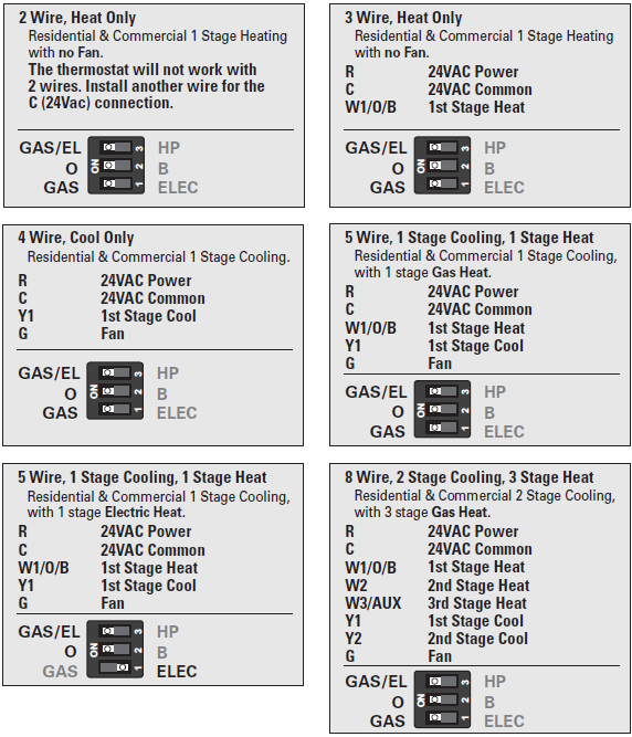
Heat Pump Systems
Troubleshooting
- SYMPTOM: The thermostat touchscreen buttons are not responsive.
- CAUSE: The touchscreen is out of calibration.
- REMEDY: Remove the thermostat from the backplate. Push the thermostat back onto the backplate, while keeping your finger pressed firmly against the center of the touchscreen, until the Calibration screen appears. Re-calibrate the touchscreen. See Touch Calibration section of full user’s manual.
- SYMPTOM: The display is blank.
- CAUSE: Lack of proper power.
- REMEDY: Make sure the power is on to the HVAC and that you have 24vac between R & C.
- SYMPTOM: The air conditioning does not attempt to turn on.
- CAUSE: The cooling setpoint is set too high.
- REMEDY: Lower the cooling setpoint or lower the cooling set-point limit. See Setpoint Limits.
- SYMPTOM: The heating does not attempt to turn on.
- CAUSE: The heating setpoint is set too low.
- REMEDY: Raise the heating setpoint or raise the heating set-point limit. See Setpoint Limits.
- SYMPTOM: When controlling a residential heat pump, and asking for cooling, the heat comes on.
- CAUSE: The thermostat reversing valve dip switch is set for “B”.
- REMEDY: Set the reversing valve jumper for “O”.
- SYMPTOM: When calling for cooling, both the heat and cool come on.
- CAUSE: The thermostat equipment dip switch is configured for “HP” and the HVAC unit is a Gas/Electric.
- REMEDY: Set the equipment dip switch for “Gas”.
- SYMPTOM: Air handler control board fuse blows when thermostat is attached to the backplate with power on, but does not blow until the thermostat is placed onto the backplate.
- CAUSE: The Outdoor sensor and/or sensor wiring is shorted.
- REMEDY: Check/replace Outdoor sensor and/or sensor wiring.
Warranty
One-Year Warranty: This Product is warranted to be free from defects in material and workmanship. If it appears within one year from the date of original installation, whether or not actual use begins on that date, that the product does not meet this warranty, a new or remanufactured part, at the manufacturer’s sole option to replace any defective part, will be provided without charge for the part itself provided the defective part is returned to the distributor through a qualified servicing dealer.
THIS WARRANTY DOES NOT INCLUDE LABOR OR OTHER COSTS incurred for diagnosing, repairing, removing, installing, shipping, servicing or handling of either defective parts or replacement parts. Such costs may be covered by a separate warranty provided by the installer. THIS WARRANTY APPLIES ONLY TO PRODUCTS IN THEIR ORIGINAL INSTALLATION LOCATION AND BECOMES VOID UPON REINSTALLATION.
LIMITATIONS OF WARRANTIES: ALL IMPLIED WARRANTIES (INCLUDING IMPLIED WARRANTIES OF FITNESS FOR A PARTICULAR PURPOSE AND MERCHANTABILITY) ARE HEREBY LIMITED IN DURATION TO THE PERIOD FOR WHICH THE LIMITED WARRANTY IS GIVEN. SOME STATES DO NOT ALLOW LIMITATIONS ON HOW LONG AN IMPLIED WARRANTY LASTS, SO THE ABOVE MAY NOT APPLY TO YOU. THE EXPRESSED WARRANTIES MADE IN THIS WARRANTY ARE EXCLUSIVE AND MAY NOT BE ALTERED, ENLARGED, OR CHANGED BY ANY DISTRIBUTOR, DEALER, OR OTHER PERSON WHATSOEVER.
ALL WORK UNDER THE TERMS OF THIS WARRANTY SHALL BE PERFORMED DURING NORMAL WORKING HOURS. ALL REPLACEMENT PARTS, WHETHER NEW OR REMANUFACTURED, ASSUME AS THEIR WARRANTY PERIOD ONLY THE REMAINING TIME PERIOD OF THIS WARRANTY.
THE MANUFACTURER WILL NOT BE RESPONSIBLE FOR:
- Normal maintenance as outlined in the installation and servicing instructions or owner’s manual, including filter cleaning and/or replacement and lubrication.
- Damage or repairs required as a consequence of faulty installation, misapplication, abuse, improper servicing, unauthorized alteration or improper operation.
- Failure to start due to voltage conditions, blown fuses, open circuit breakers or other damages due to the inadequacy or interruption of electrical service.
- Damage as a result of floods, winds, fires, lightning, accidents, corrosive environments or other conditions beyond the control of the Manufacturer.
- Parts not supplied or designated by the Manufacturer, or damages resulting from their use.
- Manufacturer products installed outside the continental U.S.A., Alaska, Hawaii, and Canada.
- Electricity or fuel costs or increases in electricity or fuel costs for any reason whatsoever including additional or unusual use of supplemental electric heat.
- ANY SPECIAL INDIRECT OR CONSEQUENTIAL PROPERTY OR COMMERCIAL DAMAGE OF ANY NATURE WHATSOEVER. Some states do not allow the exclusion of incidental or consequential damages, so the above may not apply to you.
This warranty gives you specific legal rights and you may also have other rights which may vary from state to state.
CAUTION: Follow the Installation Instructions before proceeding. Set the thermostat mode to “OFF” prior to changing settings in setup or restoring Factory Defaults.
FCC Compliance Statement
This equipment has been tested and found to comply with the limits for an intentional radiator, pursuant to Part 15, subpart C of the FCC rules. These limits are designed to provide reasonable protection against harmful interference in a residential installation. This equipment generates, uses and can radiate radio frequency energy and, if not installed and used in accordance with the instructions, may cause harmful interference in radio communications. However, there is no guarantee that interference will not occur in a particular installation. If this equipment does cause harmful interference to radio or television reception, which can be determined by turning the equipment off and on, the user is encouraged to try to correct the interference by one or more of the following measures:
- Reorient or relocate the receiving antenna.
- Increase the separation between the equipment and the receiver.
- Connect the equipment into an outlet on a circuit different from that of the receiver.
- Consult the dealer or an experienced radio or TV technician for help.
Notice: Only peripherals complying with FCC limits may be attached to this equipment. Operation with noncompliant peripherals or peripherals not recommended by Venstar, is likely to result in interference to radio and TV reception. Changes or modifications to the product, not expressly approved by Venstar could void the user’s authority to operate the equipment.
FCC – INDOOR Mobile Radio Information:
To comply with FCC/IC RF exposure limits for general population / uncontrolled exposure, the antenna(s) used for this transmitter must be installed to provide a separation distance of at least 20 cm from all persons and must not be co-located or operating in conjunction with any other antenna or transmitter. This Device complies with Industry Canada License-exempt RSS standard(s). Operation is subject to the following two conditions:
- this device may not cause interference.
- this device must accept any interference, including interference that may cause undesired operation of the device.
Under Industry Canada regulations, this radio transmitter may only operate using an antenna of a type and maximum (or lesser) gain approved for the transmitter by Industry Canada. To reduce potential radio interference to other users, the antenna type and its gain should be so chosen that the equivalent isotropically radiated power (e.i.r.p.) is not more than that necessary for successful communication.
We, Source 1, declare under our sole responsibility that the device to which this declaration relates: Complies with Part 15 of the FCC Rules. Operation is subject to the following two conditions:
- this device may not cause harmful interference.
- this device must accept any interference received, including interference that may cause undesired operation.
This color touchscreen has the ability to receive updates to its firmware. Periodically firmware updates are released by the manufacturer to add features and/or performance enhancements. This manual was produced reflecting the most current firmware/feature set at the time of publication, firmware rev. 6.85. Firmware releases after rev. 6.85 may not be adequately depicted in this manual. Please refer to the appropriate website or contact your place of purchase to learn about changes to the thermostat after firmware release 6.85.

Glossary of Terms
- Auto-Changeover: A mode in which the thermostat will turn on the heating or cooling based on room temperature demand.
- Cool Setpoint: The warmest temperature that the space should rise to before cooling is turned on (without regard to deadband).
- Deadband: The number of degrees the thermostat will wait, once a setpoint has been reached, before energizing heating or cooling.
- Differential: The forced temperature difference between the heat setpoint and the cool setpoint in Auto Mode.
- Heat Setpoint: The coolest temperature that the space should drop to before heating is turned on (without regard to deadband).
- Icon: The word or symbol that appears on the thermostat display.
- Mode: The current operating condition of the thermostat (i.e. Off, Heat, Cool, Auto).
- Non-Programmable Thermostat: A thermostat that does not have the capability of running Time Period Programming.
- Override: Changing the state from occupied to unoccupied, or from unoccupied to occupied settings.
- Programmable Thermostat: A thermostat that has the capability of running Time Period Programming.
- Temperature Swing: Same as Deadband.
- Time Period Programming: A program that allows the thermostat to automatically adjust the heat setpoint and/or the cool setpoint based on the time of the day. Same as Schedule.
REFERENCE:
DOWNLOAD MANUALS:
Source1 S1-TBPU435-S High-Resolution Digital Thermostat Owners Manual

Source1 S1-TBPU435-S High-Resolution Digital Thermostat Owners Manual