Smarttemp SMT-80 Digital Thermostat

INTRODUCTION
Thank you for your purchase of the SMT-80 digital thermostat or the SMT-80RF wireless thermostat by Smart Temp Australia P/L. Please take the time to read and understand these simple instructions so that you may benefit from the advanced features and functions integrated into this quality product. The SMT-80 is available in 2 versions. In terms of the user experience the two versions are almost identical. The only difference being the SMT-80RF communicates to the heating and cooling system by radio frequency rather than being hardwired to it. This feature permits you to take the thermostat into any room with you* to ensure better temperature control where you are The Smart Temp SMT-80 is a digital, non-programmable thermostat that has many energy saving functions. It will control your heating and/or cooling system precisely and in an energy efficient manner.
Operating the Heating and Cooling System
A backlit display shows current room temperature as well as other important information. Four buttons are provided to permit the control of the SMT-80 functions.
 Up Button
Use this button to increase the set temperature.
Down Button
Use this button to decrease the set temperature.
Mode Button
Each tap of the Mode button will cycle the SMT-80 through all available modes. (Heat, Cool and Off)
Note – Not all modes may be active on your SMT-80.
Off – The Heating and Cooling System is OFF
“OFF” is displayed in the LCD when the SMT-80 is OFF “OFF” will flash in the LCD if the SMT-80 has been remotely turned off by the Auto Off or a remote input. In this case you may not be able to turn the SMT-80 on using the Mode button.
Heat Mode – Only the Heating System Will Operate
“Heat ON” will be shown when the heating is running. “Heat” will flash if the heat delay timer is running, please wait up to 5 minutes.
Cool Mode – Only the Cooling System Will Operate
“Cool ON” will be shown when the cooling is running. “Cool” will flash if the cool delay timer is running, please wait up to 5 minutes. Auto Mode – Both the Heating and Cooling Systems Will Operate Auto mode will Heat when the room is cold or cool when the room is warm automatically.
![]() Light/Fan Button
Light/Fan Button
Selects Auto Fan or Continuous Fan and/or brings on the display backlight.“Fan” will be shown whenever the fan is running or “Fan On” will be shown whenever the fan button was used to switch the fan on manually.
Adjusting Your Set Temperature
Make sure Heat, Cool or Auto mode is selected. Press the [Up] or [Down] button and the display will change and show “SET”, and “Heat Set” or “Cool Set” with the current set temperature in the main part of the display. Continue to press the [Up]
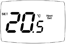
or [Down] button until your desired set temperature is shown. If Auto mode is selected, you are first given the opportunity to adjust the cool and then the heat set temperature separately.
Note – Your range of adjustment may be limited by the installer. “Set Limit Reached” is shown when this is the case.
Low Battery Warning
Your SMT-80 controller may be powered by 2 x AA Alkaline batteries. When these batteries run low a battery symbol will be shown on the display and the backlight will be disabled. Normal heating and cooling will still function. If you ignore this first warning eventually the heating and cooling will shut down and the display will show only the flashing low battery symbol and the text “Low Batt”.
Replace with AA ALKALINE batteries only.
SMT-80 RF Signal Icon![]()
The “RF” signal indicator will remain steady when communication is established and will flash when the signal is absent. If communication is lost for extended an time, the SMT-80 will stop all heating and cooling. The SMT-80 RF has a maximum range of 30M inside depending on wall construction and other factors that may limit the range.
Motorized Zone Damper Control Function (Optional)
Your SMT-80 & SMT-80RF can be set up by your installer to either control a conventional heating and/or cooling system OR to control a motorized zone damper. In Zone damper control mode your SMT-80 or SMT-80RF compares the current zone temperature with your set temperature and the temperature of the air produced by your heating or cooling system (that is controlled by its own thermostat). If the air produced by your heating and cooling system will bring your zone to your desired temperature it will open a motorized damper and allow conditioned air into the zone. If the air produced by your heating and cooling system is not suitable to bring your zone to your desired temperature it will close the motorized damper and block the flow of air into your room.
Note – In Zone Damper Control Mode the SMT-80 or SMT-80RF is NOT controlling the main heating or cooling system.
Hint – If your installer has set your SMT-80 or SMT-80RF to Motorised Zone Damper Control mode the decimal place in the room temperature display will blink.


The Installer options below relate to both the SMT-80 and SMT-80RF versions except where noted.
NOTE – Changing the settings in this menu can seriously affect the safe operation and function of your heating and cooling system. If you are unsure about the functions of the settings in this menu then it is strongly recommended that you don’t adjust them. To enter the Installer menu first press and hold the [Mode] and [Up] button (simultaneously) on the controller for 5 seconds. The heating and cooling (if running) will stop and the display will show “15”. Using the [Up] button, adjust this to read “21” or the previously set PIN if changed from the factory default of “21”.
SMT-80 Terminal Identification
| C | 24V Neutral (Optional) |
| Rc | Active Cooling (Powers Y & G Terminals) |
| Rh | Active Heating (Powers W Terminal) |
| W/OB | Heat (HC Mode) or Reversing Valve (HP Mode) |
| Y | Cool (HC Mode) or Compressor (HP Mode) |
| G | Fan |
| TT | Used For Remote Sensors or Switches |
Press the [Mode] button to enter the Installer menu
Pressing the [Fan/Light] button will move you forward through the menu items. Pressing the [Mode] button will step you backward through the menu items. Use the [Up] and [Down] buttons to adjust the currently displayed menu item. To exit the installer menu, press and hold either the [Mode] or [Fan] button for 5 seconds. No activity for 30 seconds will auto-exit this menu. The Installer menu is dynamic. Functions not applicable will not be shown in this menu. For example, if you set the SMT-80 or SMT-80RF as a heat-only thermostat, permitted modes and cooling set limit items will not be shown.
Installer Settings (Default Values Shown in BOLD)
Fn Thermostat Control Functions (HO) These menu items define how the relays in the SMT-80 control the Heating and Cooling system.
- HO – Heating Only No Fan (No manual fan function)
- HF – Heating with Fan Control (Manual fan available)
- HE – Heating with Electric Fan
- CO – Cool Only
- HC – Heat Cool with Gas Fan
- HCE – Heat Cool with Electric Fan
- HPo- Heat Pump – Rev Valve in Cool
- HPb – Heat Pump – Rev Valve in Heat
- dC – Damper Control Mode
Mode (Only Applies if Fn = Heat Cool or HP Mode) (nn) This sets the modes than can be selected by the user
A – Auto Mode (Off – Heat – Cool – Auto – Off)
AO – Auto Only (Off – Auto – Off)
nn – Manual (Off – Heat – Cool – Off)
HL Heat Limit (35⁰C)
Defines the highest permitted Heat setpoint
Range – Off / 0 to 50⁰C
CL Cool Limit (15⁰C)
Defines the lowest permitted Cool setpoint
Range – Off /0 to 50⁰C⁰
Sp Span (1.0)
Sets the range difference between heating and cooling On/Off points.
Range 0.3⁰C to 1.5⁰C
db Deadband (1.0)
Defines how close the user can set the heating and cooling setpoints to each other in Auto Mode.
Range 0.0 to 3.0⁰C
CA Room Sensor Calibration (0.0)
Adjusts the accuracy of the room temperature sensor.
Range -5.0 to +5.0
SS Response Speed of temperature sensor (FSt)
Defines how fast the room sensor responds to temperature changes.
VS Very Slow
S Slow
Nor Normal
FSt Fast
VF Very Fast
AOt Auto-Off Timer (0-Off)
If set, the SMT-80 will automatically turn “Off” once the countdown timer has expired. (Note – “OFF” will flash on the SMT-80 LCD)
Range 0 (off) to 12 hours
Ct Compressor Timer (Cooling or HP Mode Only) (On)
(This menu item not shown when thermostat function = dC)
Set the compressor 4 min anti-cyclic timer.
Off
On
tt TT Terminals Function (RS)
(This menu item not shown when thermostat function = dC)
RS – Remote Sensor – Will Disable Onboard Sensor
AU – Average – Average Remote and Onboard Sensor
Ot – Used to Measure Outside Air Temperature
FO – Remote Off Function – Will Force SMT-80 Off
PIr – Wire a standard PIR security sensor to have automatic occupancy detection. After 30 minutes of no movement the SMT-80 will turn OFF
Note – “OFF” will flash on the SMT-80 LCD when FO or PIR function is enabled.
dIS Display units (C)
Sets Units of Display
C
F (Deg F Mode Activates 5⁰C Anti-Freeze Function)
Pin Installer Menu PIN (21)
Permits you to change the required PIN to enter the installer menu.
Range 0-99 (Do not forget any new pin entered)
RsT Factory Reset
Change 0 to 1 then exit installer menu to initiate a factory reset. Caution – this will also change how the SMT-80 controls the Heating and /or Cooling system.
SMT-80 Wiring Examples
2 Wire Gas Heater (Select HO)
Mounting

Place a small screwdriver into the two slots at the bottom edge of the wall controller to unclip it from the base. It hinges at the top. To close the case, hook the wall controller on its base and swing it down until it locks in place. Gently press to lock it in place. Place the SMT-80 in a location not affected by drafts or direct sunlight and in an open location approximately 1.5M from the floor.

SMT-80 Specifications
- Power ……………………………. 24 VAC +/- 15% and/or Battery
- Battery Type ………………………………………. AA Alkaline ONLY
- Battery Life (Approx) …………………………………………… 1 year
- Backlight ……………………………………………………… White LED
- Viewing Angle ……………………………………… +60 to -0 Degree
- Relay Rating …………………………………………………… 2A @24V
- Accuracy ………………………………………………………… +/- 1.2⁰C
- Size …………………………………………………… 128 x 86 x 25mm
- Environmental ……………………………………………………… IP33
- Warranty ……………………………. 36 Months (Return to Base)
- Plastic ………………………………….. ABS /Poly Flame Retardant
- Certification …………………………………………….. CE (Australia)
SMT-80RF Wiring Examples
The SMT-80RF is a 2-part controller that consists of a battery-powered controller and a 24VAC-powered receiver. The two parts communicate with each other via radio frequency (433MHz). The battery-powered controller measures the temperature of the room that it is in and transmits data to the receiver module fitted in the heating and cooling system. This permits you to move the battery-powered controller from room to room should you wish.
Note 1 – If moving the battery-powered controller do not place it on any warm or cool surfaces as this will affect the comfort of the room.
Note 2 – The maximum distance the battery controller can be from the receiver is typically 30M indoors.
Pairing the Controller and Receiver
Your Controller and Receiver should be “pre-paired” when you receive them. If for any reason you need to repair the units, the steps are detailed below. This may be necessary when you have multiple SMT-80RF in close proximity to each other to permit you to select different transmission channels for each paired unit (as indicated in step 4 below).
- Ensure you have 2 “AA” alkaline batteries fitted to the SMT-80 Controller and it is powered on.
- Ensure the SMT-80 Receiver module is powered on being hardwired with 24VAC. (The amber data link will blink a heartbeat).
- Press and hold both the [Up] and [Light /Fan] buttons on the SMT-80RF Controller until the display changes and shows the currently selected channel number.
- If you wish – adjust the channel with the [Up] or [Down] button. (If you have multiple units in your home or office they should all have a different channel number)
- Press and hold the [Pair] button on the Receiver until the green pair light blinks.
- Press the [Fan] button on the SMT-80 Controller to initiate the pairing process. The SMT-80 Controller will show the RF signal confirmed icon on the display and the green paired LED will remain ON solid when the units are paired. When data is being passed between the Controller and the Receiver the amber “data” LED will flash.
Receiver Module Wiring

The SMT-80RF Receiver module should be mounted in a clean, dry location and within 30M of the proposed Controller location. (Note – the range varies based on the environment) Avoid placing the Receiver module inside an earthed metal case such as a gas heater enclosure as this will significantly reduce the RF signal range.
SMT-80RF Troubleshooting
No LEDS on the Receiver module
Check 24VAC power supply is in the CR terminal
Poor Range
Check Receiver location
Ensure the Receiver not mounted inside a metal enclosure
Check SMT-80 batteries
Check for other strong RF signals that may be close
Pairing Process Fails
Remove batteries and power down the receiver for 5 minutes and try again Green LED Off / RF Signal Icon Blinking
See Poor Range (Above)
Try “Re-Pairing” the SMT-80 with the Receiver module
Amber LED Rapidly Blinking
This is normal – data is being transmitted/received
SMT-80RF Receiver Module Terminal Identification
| C | 24V Neutral |
| R | 24V Active |
| Rly Com | Input to all Relays (Typically Looped to “R” Above) |
| W/OB | Heat (HC Mode) or Reversing Valve (HP Mode) |
| Y | Cool (HC Mode) or Compressor (HP Mode) |
| G | Fan |
| T T | Used for Supply Air Sensor in Damper Control Mode |
SMT-80RF Receiver Module Specifications
- Power ………………………………………………….. 24 VAC +/- 15%
- Relay Rating …………………………………………………. 5A @240V
- Accuracy ………………………………………………………… +/- 1.2⁰C
- Size …………………………………………………… 140 x 88 x 40mm
- Environmental ……………………………………………………… IP20
- Warranty ……………………………. 36 Months (Return to Base)
- Plastic ………………………………….. ABS /Poly Flame Retardant
- Certification ………………………………………….. CTick(Australia)
SMT-80 and SMT-80 RF Manual – Version 1.0 www.thermostat.com.au
Smart Temp Australia. 2020 www.smarttemp.com.au +61 3 97630094
REFERENCE:
DOWNLOAD MANUALS:
Smarttemp SMT-80 Digital Thermostat User Manual
![]()