
Siemens RDY2000BN BACnet Enabled Commercial Room Thermostat

Product Information
The BACnet Enabled Commercial Room Thermostat is designed for use with any Energy Management A system providing BACnet MS/TP communication. Use Commercial Room Thermostat RDY2000BN for stand-alone operations. Scan the QR code on the thermostat rear housing for additional information.

Product Number
RDY2000BN
Product Specifications
| System Compatibility | |
| Conventional | Up to 3 Heating/3 Cooling stages |
| Heat Pumps | Up to 4 Heating/2 Cooling stages |
| Electrical Characteristics | |
| Power Supply | 24 Vac +/-20%, Class 2, 4A max. |
| Power Usage | 4 VA (maximum) |
| Output Relay
Ratings |
Pilot duty, 1A max. per output, 4A
max. total |
| MS/TP Load | 1/8 (96 KΩ), internal network bias |
| Ambient Limitations | |
| Operating
Temperature |
23°F to 122°F (-5°C to 50°C) |
| Storage/Shipping
Temperature |
-13°F to 158°F (-25°C to 70°C) |
| Relative Humidity | Up to 95% (non-condensing) |
| Enclosure | |
| Rating | NEMA 1 |
NOTE
The RDY2000BN is not battery-powered. It
requires 24 Vac power from the HVAC
equipment at terminals RH/RC and C.
Caution Notations
| CAUTION: |  |
Equipment damage or loss of data may occur if you do not follow the procedures as
specified. |
| WARNING: | |
Personal injury or loss of life
may occur if you do not follow the procedures as specified. |
Required Tools
- 1 Phillips screwdriver
- 1/8” flat-blade screwdriver
- Drill with a 1/8″ drill bit
Expected Installation Time
15 minutes
CAUTION
The RDY2000BN is an advanced controller designed to be installed by professional HVAC technicians. Installation by non-qualified personnel may result in degraded system efficiency, occupant discomfort, or equipment damage.
Prerequisites
WARNING
Turn off power to the HVAC equipment before attempting to remove an existing thermostat or install a new thermostat. All work must be performed in accordance with the applicable codes and standards.
- Energy Management System Network Plan and HVAC schematics are
- MS/TP run to thermostat using 24 AWG Low Capacitance 1.5 Twisted Shielded Pair Shield and reference terminator to be earth grounded only at one point on the network.
- HVAC equipment connections run to the thermostat with 18 gauge thermostat
- Sensor connections run to the thermostat with 22 gauge twisted pair cable or remote sensor Do not exceed 164 ft (50 m).
Installation
Refer to Energy Management System Network Plan for MS/TP installation and configuration parameters.
- Verify power to HVAC equipment is turned
- Optional: To replace an existing thermostat:
- Remove the existing
- Record wiring connections to existing thermostat base plate
- Remove the existing base
- Install the new thermostat base
- Feed all installed wires through the opening in the base plate and strip to 3/16-inch (5 mm).
- Secure the base plate to the mounting surface using supplied
NOTE: Ensure that the UP arrows embossed

- Attach the HVAC system wires to the appropriate terminals on the thermostat base plate Figure
- Verify HVAC equipment schematics for required circuit connections to thermostat Wiring Diagrams, Figure 4 and Figure
- Verify each 24 Vac transformer secondary neutral is connected to the HVAC
- If a single transformer is used, leave the Jumper RH-RC in place. Connect 24 Vac to RC terminal, and neutral to terminal
- If separate transformers are used for heating and cooling systems, remove the Jumper RH-RC. Connect cooling 24 Vac to terminal RC, neutral to terminal C and heating 24 Vac to terminal
- Optional: Auxiliary Output 3 can be changed to a dry (unpowered) contact by removing Jumper RC-C3 and connecting dry contact wires to OUT3 and C3. See Wiring Diagrams, Figure 6.
- Optional: If using Configurable Inputs 1 to 4 or Auxiliary Outputs 1 to 3, use setup parameters P301 to P320 to set functionality.
CAUTION
To ensure signal integrity observe MS/TP network wire polarity, reference terminator and shield earth grounded at one location, two end-of-line terminators, and if required an external network bias device. MS/TP devices from some vendors may refer to input A as (-) and input B as (+) or may require external network bias. For RDY2000BN, NETA is non-inverting input A (+) internally biased high, NETB is inverting input B (-) internally biased low to REF (↓), and external bias is not required.
- Refer to the network plan for MS/TP wire color code used for (+), (-), and (↓).
- See Figure 7 for wiring the thermostat at the middle of line (two MS/TP cables) or at the end of line (one MS/TP cable).
- If the thermostat at the middle of line, connect terminals to two MS/TP cables with (+) to NETA, (-) to NETB, and (↓) to Connect shield wires together and insulate.
- If the thermostat at the end of line, connect terminals to one MS/TP cable and one end-of-line terminator with (+) and terminator to NETA, (-) and terminator to NETB, and (↓) to REF. Verify shield is connected to the earth’s ground and insulated.
- Attach the thermostat to the base plate by engaging tabs at the top and rotating the thermostat downward until securely seated on the base plate.
- Secure the thermostat to the base plate with the Phillips screws (provided), using the holes at the bottom of the housing.
- Remove the thermostat LCD screen cover.
The installation is now complete. Restore power, and continue to Thermostat Setup.
Thermostat Setup

Thermostat Display
Navigation Bar
Only one function can be selected at a time. The small bar (cursor) below the function icon indicates that a function is selected. Pressing an icon twice navigates back to the Main screen.
A double bar cursor below the Settings icon ![]() indicates that you are in Programming mode. The navigation bar at the bottom of the display consists of four function icons
indicates that you are in Programming mode. The navigation bar at the bottom of the display consists of four function icons
Table 1. Navigation Bar Icons
| Icon | Name | Purpose |
 |
Setpoint |
Enables adustment of temperature and humidity (if applicable) setpoints. Unit will display heating
setpoint if in Heating mode or cooling setpoint if in Cooling mode. |
 |
Fan Control | Enables fan relay to be controlled as needed by thermostat (AUTO) or
to be on continuously (ON). |

|
Mode Selector |
Enables manual changeover between Heating and Cooling mode. AUTO will enable the thermostat to automatically switch between heating and cooling mode as required. OFF will disable all
control functions. |
 |
Settings |
Enables Scheduler, Time/Date, and Installer Set Up configuration. Also enables access to service reminder
and fault messages. |
Service Reminders and Fault Messages
- Service reminders appear on the right side of the screen:
- SERVICE UV LAMP
- SERVICE HUMIDIFIER
- SERVICE AIR FILTER
They are determined by the timer set in the Installer Setup Menu and can be cleared by pressing the Settings icon ![]() , and then SERVICE. See Clearing Service Reminders.
, and then SERVICE. See Clearing Service Reminders.
- Active fault messages appear at the left side of the home screen:
- CONNECTION LOST (Not applicable to this model)
- DEMAND RESPONSE (Not applicable to this model)
- SERVICE REQUIRED (See Viewing Fault Messages)
Fault messages are automatically cleared when the root cause of the failure is resolved.
Status Bar
The status bar at the top of the display consists of 11 icons
Table 2. Status Bar Icons
| Icon | Name | Meaning |
| |
Occupied |
Space is occupied, based on Schedule and/or Occupancy Sensor. |
| |
Keypad Lock | Keypad is locked. |
| |
Scheduler | Unit is running on the local schedule. |
 |
Override |
The Scheduler is being overridden by local control. |
|
|
Humidity Control Indicator |
Droplet and (+) indicates humidification relay is on. Droplet and (-) indicates dehumidification relay is on. If neither relay is on,
the water droplet does not appear. |
 |
Fan | Fan relay is on. |
| |
Fresh Air | Economizer Enable/ Ventilation relay is on. |
| |
Cool Mode | The system is actively in cooling mode. |
| |
Heat Mode | The system is actively in heating mode. |
 |
Heating/Cooling Stages | Each segment represents one stage of heating or cooling. |
 |
Auxiliary Heating |
Auxiliary heating stage: AUX=Stage 1: Aux
2=Stage 2 |
Wiring Diagrams

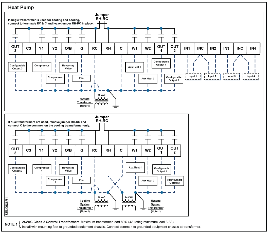
Figure 5. Wiring Schematic, Heat Pump

Set-up Wizard
When unit is powered up for the first time, WIZARD displays. This tool is used to program the basic system parameters. Additional parameters can be accessed directly via Installer/Expert Set-up menus.
NOTE: The thermostat will not start the control sequence until Set-up Wizard is complete.
- Press WIZARD to access the
NOTE: Press left and right arrows to select parameters. Press + or – to change parameter settings.
- After completing all Wizard parameters, press
Confirm to save and complete.
- INSTALLER
- Press INSTALLER to access Installer
- Enter values obtained from the Energy Management System Network Plan for the 600 Series BACnet Configuration Parameters. See Table
NOTE: Required to communicate with the Energy Management System
- If setup is complete, press the Settings icon
 to exit the Set-up Wizard. If further setup is needed, continue to Step
 - Select and modify additional parameters. See Table 3 through Table 9 for all parameter descriptions. Use the space provided in Table 16 to record any modified parameter
- Press the Settings icon [ ] when finished to exit
Programming Temperature Setpoints
- Touch the center of the Home screen to access the room temperature screen. Use the left
 and
and  right arrows adjacent to the text line to display the room temperature and
 - Touch the Setpoint icon of the screen toaccess room temperature and humidity setpoints.
NOTE: Only the setpoints in the current mode display and can be modified. For instance, if the thermostat is in heating mode, only the heating setpoint displays and can be modified. If the thermostat is in AUTO mode, both the heating and cooling setpoints will be displayed and can be modified Use the left and![]() right arrows to access the different setpoints, and the + and – icons to adjust the setpoints.
right arrows to access the different setpoints, and the + and – icons to adjust the setpoints.
Programming Time and Date
- Touch the center of the Home screen.
- Press the Settings icon. SCHEDULER displays.
- Use the left and right arrows to access the Time menu. Press TIME. Press the two-digit hour display to change the hour, or press the two-digit minute display to change the minutes. Press the left arrow to decrease the value, and the right arrow to increase the value.
- Press the Settings icon to save.
- Use the left and righ arrows to access the Date menu. Press DATE. Use the arrows to select the month and year; use +/- to set the date.
- Press the Settings icon to save.
Installer Menu
- Touch the center of the Home screen.
- Press the Settings icon
- SCHEDULER displays.
- Press the left arrow
- Press INSTALLER.
- Using the lower left and right arrows, enter the password.
- Press PASSWORD to accept the password.
NOTE: The Installer Level default password is 00:00 - Press the Settings icon to accept changes and return the unit to the Home screen.
NOTE: If you do not provide input, the thermostat will automatically exit the Installer menu and resume normal system control after five minutes.
Programming the Schedule
- Touch the center of the Home screen.
- Press the Settings icon . SCHEDULER will display.
- Press SCHEDULER.
- Use the left and right arrows to select the day. Press the day to select.
- Use the + and – icons to set the mode: Comfort (ON) or Economy (ECO).
- Use the left and right arrows to adjust the start time for each programming period. Adjust the hours and minutes individually by pressing the two-digit hour or two-digit minute fields.
- Use the left and right arrows to select the next event for the given day. Configur remaining events as desired.
- Press the Settings icon then the left and right arrows to select the next day. Repeat steps 5 through 7 until the schedule is fully programmed
Maintenance
Locking/Unlocking the Touch Screen To prevent unauthorized access to thermostat settings, use Parameter P211 to configure screen lockouts. The lock icon![]() indicates that the screen is locked. To unlock the keypad, do the following:
indicates that the screen is locked. To unlock the keypad, do the following:
- Touch the center of the Home screen to access the room temperature screen.
- Press the Settings icon once and LOCKED displays.
- Press and hold the Settings icon for 5 seconds; PASSWORD displays.
- Using the lower left and right arrows, enter the INSTALLER password.
- Press PASSWORD to accept the password.
- Set Parameter 211 (Keypad Lockout)
 to OFF to disable keypad lockout.
 - Touch the Setpoint icon
 of the screen to return to the Home screen.
Clearing Service Reminders
The thermostat displays SERVICE REQUIRED and an associated service reminder if the reminder timer (Parameters 208 – 210) has timed out. To clear these, do the following:
- Touch the center of the Home screen to access the room temperature screen.
- Press the Settings icon and SERVICE displays.
- Use the left and right arrows to select the service reminder.
- To clear, touch the + icon and the display changes from to OFF.
- Counter resets and reminder icons turn off.
Viewing Fault Messages
The thermostat displays SERVICE REQUIRED if a sensor fails or a service reminder has timed out. To view these, do the following:
- Touch the center of the Home screen to access the room temperature screen.
- Press the Settings icon and SERVICE isplays.
- Press SERVICE and review faults. Use the left and right arrows to see all faults.
NOTE: The fault message is automatically cleared when the root cause of the failure is resolved.
Resetting the Unit to Factory Defaults
CAUTION
The following steps set ALL parameters to factory defaults (including passwords), and restart the Set-up Wizard.
- Log in as either an Installer or Expert.
- Press the left arrow. RESTORE displays.
- Press + to change the setting to YES.
- Press RESTORE.
This resets the unit and restarts the Set-up Wizard.
Table 3. 100 Series Parameters
| Parameter | Definition | Display | Value Range | Default | Extended Definition | Notes |
| P101* | System Type | SYS TYPE | CO(1)
HP(2) |
CO | CO = Conventional HP = Heat Pump | |
|
P102* |
Cooling Stages |
COOL STGS |
0
1 2 3 |
2 |
Sets number of cooling stages |
|
|
P103* |
Heating Stages |
HEAT STGS |
0
1 2 3 |
2 |
Sets number of heating stages |
|
|
P104* |
Aux Heating Stages |
AUX HT STG |
0
1 2 |
0 |
Sets number of auxilary heat stages |
|
|
P105* |
Fan Operation |
HTG FAN |
ELE gAS |
ELE |
ELE = Fan Relay energized on call for heat
gAS = Fan Relay always energized unless Aux Heat calls for heat. |
|
|
P106* |
Reversing Valve |
REV VALVE |
0
b |
0 |
0 = Energize reversing valve on cooling b = Energize reversing valve on heating | ~ This parameter only
appears if system is heat pump |
|
P107* |
Scheduler Days |
SCHEDULER |
1 2 3 7 OFF |
2 |
1 = Schedule all days with same schedule 2 = One schedule for M-F and another for
Sat + Sun 3 = One schedule for M-F, Sat + Sun scheduled individually 7 = Schedule each day individually OFF = Scheduler Disabled |
|
| P109* | Units | UNITS | F C | F | ||
|
P110 |
Changeover |
AUTO CHNGE |
YES NO |
YES |
~ This parameter does not appear on systems that are heat only or
cool only |
|
|
P111 |
Changeover Deadband |
DEADBAND |
3
4 5 6 7 8 9 |
5°F |
Deadband in degrees F |
~ This parameter does not appear if CHANGEOVER = M ~ This parameter does not appear on systems that are heat only or cool only |
|
P112 |
Daylight Savings |
DAYLT SAVE |
YES NO |
NO |
Y = Auto adjust for daylight savings time N = Does not auto adjust for daylight
savings time |
|
| P113 | Display Temp Setpoint | TMP SP DIS | 0=Absolute 1=Relative | 0=Absolute | Selection of setpoint display: absolute or relative value | |
Table 4. 200 Series Parameters
| Parameter | Definition | Display | Value Range | Default | Extended Definition | Notes |
| P201 | Heat Temp Limit | HEAT LIMIT | 45 – 95 | 95°F | Sets maximum allowable heating setpoint | ~ Does not appear if HEAT STAGES = 0 |
| P202 | Cool Temp Limit | COOL LIMIT | 50 – 95 | 50°F | Sets minimum allowable cooling set point | ~ Does not appear if COOL STAGES = 0 |
|
P203 |
Temperature Display Offset |
TMP OFFSET |
-5 to +5 |
0°F |
Enables adjustment of control temp and display temperature in 1 degree increments.Applies only to onboard temp sensor. Indoor temp only. | |
|
P204 |
Override Time Limit |
HRS OVR RD |
“—” = unlimited; 0 = none;
2 =2 hours; 4 = 4 hours; 6 = 6 hours; 8 = 8 hours 10 = 10 hours 12 = 12 hours 24 = 24 hours 96=96 hours |
2 |
Number of hours that scheduled setpoint can be manually overridden. 0 = no override allowed |
~ This parameter does not appear if SCHEDULER = OFF |
|
P205 |
Override Temp Limit |
TMP OVR RD |
— 1
2 3 4 5 6 7 8 9 10 |
— |
Number of degrees F that are allowed above or below scheduled setpoint. — = Unlimited |
~ This parameter does not appear if SCHEDULER = OFF |
|
P206 |
Heat Pump Compressor Lock Out |
HP COMP LO |
OFF 15=15°F
20=20°F 25=25°F 30=30°F 35=35°F 40=40°F 45=45°F |
OFF |
Heat pump compressor will not operate below this outdoor temp — forcing unit to auxiliary heat |
~ Only shown if SYS TYPE = HP with AUX HEAT and there is an outdoor temp sensor ~ Must be lower than HP AUX LO |
|
P207 |
Heat Pump Auxiliary Heat Lockout |
HP AUX LO |
OFF 40=40°F
45=45°F 50=50°F 55=55°F 60=60°F |
OFF |
Heat pump auxiliary heat will not operate above this outdoor temp. |
~ Only shown if SYS TYPE = HP with AUX HEAT and there is an outdoor temp sensor
~ Must be higher than HP COMP LO |
|
P208 |
Service UV Lamp |
UV LAMP |
0-365 |
0 |
Number of days until SERVICE UV LAMP message is displayed.
0 = function disabled. |
|
|
P209 |
Service Humidifier | HMDFR SRVC |
0-365 |
0 |
Number of days until SERVICE HUMIDIFIER message is displayed. 0 = function disabled. | |
|
P210 |
Service Air Filter |
FLTR SRVC |
0-365 |
0 |
Number of days until SERVICE AIR FILTER message is displayed.
0 = function disabled. |
|
|
P211 |
Keypad Lockout |
KEY LOCK |
OFF 2
3 |
OFF |
OFF = No lockout
2 = Partial Lockout (only temp setpoint can be adjusted) 3= Total Lockout |
|
| P212 | Clock Format | CLOCK | 12
24 |
12 | 12 = 12-hour format 24 = 24-hour format |
| Parameter | Definition | Display | Value Range | Default | Extended Definition | Notes |
|
P213 |
Backlight |
LIGHT |
0-99 |
15 |
Number of seconds that backlight stays on after screen is touched. 0 = always off. | |
|
P220 |
Heating Setpoint Comfort |
COMF HT SP |
As defined in Heat Temp Limit (P201) |
70°F |
Normal occupied heating setpoint |
|
|
P221 |
Cooling Setpoint Comfort |
COMF CL SP |
As defined in Cool Temp Limit (P202) |
75°F |
Normal occupied cooling setpoint |
|
|
P222 |
Heating Setpoint Economy |
ECO HT SP |
40 – 104 |
62°F |
Normal unoccupied heating setpoint |
|
|
P223 |
Cooling Setpoint Economy |
ECO CL SP |
45 – 104 |
82°F |
Normal unoccupied cooling setpoint |
|
|
P224 |
Heating Setpoint Protection |
PROT HT SP |
40 – 104 |
40°F |
Normal minimum heating setpoint |
|
|
P225 |
Cooling Setpoint Protection |
PROT CL SP |
45 – 104 |
104°F |
Normal maximum cooling setpoint |
Table 5. 300 Series Parameters
| Parameter | Definition | Display | Value Range | Default | Extended Definition | Notes |
|
P301 |
Configurable Input 1 (IN1) |
INPUT 1 |
1
2 3 4 5 6 7 8 9 OFF |
OFF |
1 = Indoor Temperature (Remote) 2 = Indoor Temperature (Average) 3 = Supply Temp
4 = Return Temp 5 = Outdoor Temp 6 = Humidity (0-10V) 7 = CO2 (0-10V) 8 = Occupancy (DI) 9 = Fault OFF = Not Used |
~ Cannot have duplicate selections for inputs 1-4 ~ If set to 9 (fault), a DI here causes SERVICE REQUIRED segment to activate |
| P302 | Temperature Input 1 Type | TMP IN 1 | 1
2 |
1 | 1= Type 2 Thermistor
2 = 0-10V |
~ Only appears if INPUT 1 = 1/2/3//4/5 |
|
P303 |
Temperature Input 1 Low |
TMP 1 LO |
-58 —
+250F -50 — +120C |
0 |
Calibrates thermostat to low end of temp sensor signal (e.g., 0V = -40F) |
Only appears if TMP IN 1 = 1 Must be lower than TMP 1 HI |
|
P304 |
Temperature Input 1 High |
TMP 1 HI |
-58 —
+250F -50 — +120C |
120 |
Calibrates thermostat to high end of temp sensor signal at 10 volts (e.g., 10V = 250F) | Only appears if TMP IN 1 = 1 Must be higher than TMP 1 LO |
|
P305 |
Configurable Input 2 (IN2) |
INPUT 2 |
1
2 3 4 5 6 7 8 9 OFF |
OFF |
1 = Indoor Temperature (Remote) 2 = Indoor Temperature (Average) 3 = Supply Temp
4 = Return Temp 5 = Outdoor Temp 6 = Humidity (0-10V) 7 = CO2 (0-10V) 8 = Occupancy (DI) 9 = Fault OFF = Not Used |
~ Cannot have duplicate selections for inputs 1-4 ~ If set to 9 (fault), a DI here causes SERVICE REQUIRED segment to activate |
|
P306 |
Temperature Input 2 Type |
TMP IN 2 |
1
2 |
1 |
1 = Type 2 Thermistor
2= 0-10V |
~ Only appears if INPUT 2 = 1/2/3/4/5
~ SCW can be 0 or 1 |
| Parameter | Definition | Display | Value Range | Default | Extended Definition | Notes |
|
P307 |
Temperature Input 2 Low |
TMP 2 LO |
-58 —
+250F -50 — +120C |
0 |
Calibrates thermostat to low end of temp sensor signal (e.g., 0V = -40°F) |
Only appears if TMP IN 2 = 1 Must be lower than TMP 2 HI |
|
P308 |
Temperature Input 2 High |
TMP 2 HI |
-58 —
+250F -50 — +120C |
120 |
Calibrates thermostat to high end of temp sensor signal at 10 volts (e.g., 10V = 250°F) | Only appears if TMP IN 2 = 1 Must be higher than TMP 2 LO |
|
P309 |
Configurable Input 3 (IN3) |
INPUT 3 |
1
2 3 4 5 6 7 8 9 OFF |
OFF |
1 = Indoor Temperature (Remote) 2 = Indoor Temperature (Average) 3 = Supply Temp
4 = Return Temp 5 = Outdoor Temp 6 = Humidity (0-10V) 7 = CO2 (0-10V) 8 = Occupancy (DI) 9 = Fault OFF = Not Used |
~ Cannot have duplicate selections for inputs 1-4 ~ If set to 9 (fault), a DI here causes SERVICE REQUIRED segment to activate |
| P310 | Temperature Input 3 Type | TMP IN 3 | 1
2 |
1 | 1 = Type 2 Thermistor
2 = 0-10V |
~ Only appears if INPUT 3 = 1/2/3/4/5 |
|
P311 |
Temperature Input 3 Low |
TMP 3 LO |
-58 —
+250F -50 — +120C |
0 |
Calibrates thermostat to low end of temp sensor signal (e.g., 0V = -40°F) |
Only appears if TMP IN 3 = 1 Must be lower than TMP 3 HI |
|
P312 |
Temperature Input 3 High |
TMP 3 HI |
-58 —
+250F -50 — +120C |
120 |
Calibrates thermostat to high end of temp sensor signal at 10 volts (e.g., 10V = 250°F) | Only appears if TMP IN 3 = 1 Must be higher than TMP 3 LO |
|
P313 |
Configurable Input 4 (IN4) |
INPUT 4 |
1
2 3 4 5 6 7 8 9 OFF |
OFF |
1 = Indoor Temperature (Remote) 2 = Indoor Temperature (Average) 3 = Supply Temp
4 = Return Temp 5 = Outdoor Temp 6 = Humidity (0-10V) 7 = CO2 (0-10V) 8 = Occupancy (DI) 9 = Fault OFF = Not Used |
~ Cannot have duplicate selections for inputs 1-4 ~ If set to 9 (fault), a DI here causes SERVICE REQUIRED segment to activate |
| P314 | Temperature Input 4 Type | TMP IN 4 | 1
2 |
1 | 1= Type 2 Thermistor
2= 0-10V |
Only appears if INPUT 2 = 1/2/3/4/5 |
|
P315 |
Temperature Input 4 Low |
TMP 4 LO |
-58 —
+250F -50 — +120C |
0 |
Calibrates thermostat to low end of temp sensor signal (e.g., 0V = -40°F) |
~ Only appears if TMP IN 4 = 1
~ Must be lower than TMP 4 HI |
|
P316 |
Temperature Input 4 High |
TMP 4 HI |
-58 —
+250F -50 — +120C |
120 |
Calibrates thermostat to high end of temp sensor signal at 10 volts (e.g., 10V = 250°F) | ~ Only appears if TMP IN 4 = 1
~ Must be higher than TMP 4 LO |
|
P317 |
Aux Output 1 (OUT1) |
AUX OUT 1 |
1 2 3 4 5 OFF |
OFF |
1 = Humidification 2 = Dehumidification 3 = Occupied 4 = Air Quality 5 = Economizer Enable OFF = Not Used |
~ Cannot have duplicate selections for outputs 1-3
~ Air Quality not an option unless an input is set to CO2 sensor ~ If system is conventional with 3H +3C, AO1 will default to, and be locked as, stage 3 cooling. |
| Parameter | Definition | Display | Value Range | Default | Extended Definition | Notes |
|
P318 |
Aux Output 2 (OUT2) |
AUX OUT 2 |
1
2 3 4 5 OFF |
OFF |
1 = Humidification 2 = Dehumidification 3 = Occupied 4 = Air Quality 5 = Economizer Enable OFF = Not Used |
~ Cannot have duplicate selections for outputs 1-3 ~ Air Quality not an option unless an input is set to CO2 sensor |
|
P319 |
Aux Output 3 (OUT3 & C3) |
AUX OUT 3 |
1
2 3 4 5 OFF |
OFF |
1 = Humidification 2 = Dehumidification 3 = Occupied 4 = Air Quality 5 = Economizer Enable OFF = Not Used |
~ Cannot have duplicate selections for outputs 1-3 ~ Air Quality not an option unless an input is set to CO2 sensor |
|
P320 |
Independent Humidity Control |
IND HMDTY |
YES NO |
NO |
NO = Humidification & Dehumidification only when heating or cooling relay is energized
Yes = Humidification or dehumidification independent of heating/cooling |
| Parameter | Definition | Display | Value Range | Default | Extended Definition | Notes |
|
P401 |
Unit Number |
UNIT NMBR |
0-999 |
— |
Installer can use this field to link a thermostat to an HVAC unit or zone number. If any value other than — is entered, the “sleep” screen should display UNIT NUMBER in text box
above room temp display. |
|
| P402 | CO2 Set Point | CO2 SET PT | 500 —
2000 |
1000 | Only appears if an analog input is configured as a C02 sensor | |
|
P403 |
Pre- Occupancy Purge |
PRE OC PRG |
OFF 1
2 3 |
OFF |
OFF = Disabled 1 = 1 Hour
2 = 2 Hours 3 = 3 Hours |
~ Only show if an output is set to economizer and scheduler function is active |
|
P404 |
Occupancy
Sensor Min Run Timer |
OCC MRT |
3 — 60 |
30 |
Minimum run time in minutes for
occupancy detected via digital input from external sensor |
~ Only shown if an input is set to Occupancy Sensor |
|
P405 |
Semi- Continuous Fan |
CONT FAN |
0=NO 1=Yes |
NO |
~ Only shown if a schedule is present or if an input is configured for occupancy
sensor |
|
| P407 | Installer Password | INSTALL PW | 0000 —
4999 |
Current PW | ||
- Touch the center of the Home screen.
- Press the Settings icon
 SCHEDULER displays.
 - Press the left arrow.
- Press INSTALLER.
- Using the lower left and right arrows, enter the password
- Press PASSWORD to accept the password and return the unit to the Setup Menu.
NOTE: The Expert Level default password is 99:99. - See Table 3 through Table 10 and Wiring Diagrams for additional information.
- Press the Settings icon to accept changes and return the unit to the Home screen
Recovering a Lost Password
If either of the default passwords is changed, the new password(s) should be recorded and maintained for future reference. If the records are misplaced, the following procedure can be used to set new passwords:
- Cycle power to the thermostat. This can be done by loosening the securing screws on the bottom of the housing and momentarily separating the thermostat from the base plate.
- Within 80 seconds of restoring power, navigate to the Installer Set-up screen and enter 98:21 as the password.
- The thermostat will go directly to the Expert Level password screen. A new Expert Level password can now be set.
- After setting a new Expert Level password, the thermostat will return to the Home screen.
- The new Expert Level password can be used to enter the full Expert Level set-up menu where both the Expert Level and Installer Level passwords can now be set to new values.
Table 7. 500 Series Expert Settings Parameters.
(Only available if logged in as an Expert.)
NOTE: P500 Series parameters are factory-set for optimum system performance. Changing these settings may degrade efficiency and/or compromise occupant comfort.
| Parameter | Definition | Display | Value Range | Default | Extended Definition |
| P501 | Interstage Delay – Cooling | STG DLY CL | 1 to 10 minutes | 5 | Time delay before next stage of cooling will be activated. |
| P502 | Interstage Differential – Cooling | STG DIF CL | 1°F (0.5°C) to
10°F (5.0°C) |
1°F | Degrees above cooling deadband before Stage Delay timer is initiated. |
| P503 | Cooling Minimum Off Time | M O T CL | 1 to 10 minutes | 5 | Minimum time between compressor starts. |
| P504 | Cooling Minimum On Time | M R T CL | 1 to 10 minutes | 3 | Minimum run time for any stage of cooling. |
| P505 | Changeover Delay | C-O DLY | 1 to 60 | 10 | Delay in minutes before system will automatically
switch from heating to cooling (or vice versa). |
|
P506 |
Cooling Deadband |
CL DEADBND |
1°F (0.5°C) to 5°F (4.0°C) |
1°F |
The deadband is divided equally above and below setpoint. Cooling will begin when temperature exceeds upper point of deadband and ceases
when temperature falls below lower point of deadband. |
| P507 | Interstage Delay – Heating | STG DLY HT | 1 to 10 minutes | 5 | Time delay before next stage of heating will be
activated. |
|
P508 |
Interstage Differential – Heating |
STG DIF HT |
1°F (0.5°C) to 5°F (5.0°C) |
Conv. = 1°F (0.5°C) HP = 2°F
(1.0°C) |
Degrees below heating deadband before Stage Delay timer is initiated. |
| P509 | Heating Minimum Off Time | M O T HT | 1 to 10 minutes | 5 | Minimum time between heating starts. |
| P510 | Heating Minimum On Time | M R T HT | 1 to 10 minutes | Conv = 3
HP = 10 |
Minimum run time for any stage of heating. |
|
P511 |
Heating Deadband |
HT DEADBND |
1°F (0.5°C) to 5°F (4.0°C) |
1°F (0.5°C) |
The deadband is divided equally above and below setpoint. Heating will begin when temperature falls below lower point of deadband and ceases when temperature rises above upper port of
deadband. |
| Parameter | Definition | Display | Value Range | Default | Extended Definition |
|
P601 |
MS/TP MAC address |
MS–TP MAC |
0-255 |
255 |
MS/TP MAC address must be unique for the entire network 1 to 254.
In systems that support and use Master Nodes valid range to use is from 1 to 127. In systems that support and are using auto discovery leave value at default 255 NOTE: When integrating with APOGEE®, set this parameter to be a Master Node. |
|
P602 |
Baud Rate |
BAUD RATE |
A = Auto
9.6 = 9600 19.2 =19200 38.4 = 38400 57.6 = 57600 76.8 = 76800 115.2 =115200 |
A=Auto |
This parameter will set the network’s baud rate. Auto value will match detected Baud Rate in systems that support and are using auto discovery leave value at default “A” |
|
P603 |
Device Instance |
DEV ID |
0 – 4194303 |
4194303 |
Device Instance (unsigned integer 0-4194303) In systems that support and are using auto
discovery leave value at default 4194303 |
| P604 | Max Master | MAX MASTER | 1–127 | 127 | Max Master |
| P605 | Serial number | SER NR | Display Only | Display Only | Display Serial number, 10 digit hex, programmed in factory |
| P606 | Max Info Frames | MAX FRAME | 1– 10 | 1 | Max Info Frames |
CAUTION
See the Energy Management System Network Plan before entering values in the RDY2000BN 600 Series BACnet Configuration Parameters. Incorrect values will prevent connection to the Energy Management System
| Parameter | Definition | Display | Value Range | Default | Extended Definition |
| P701 | Firmware | FIRMWARE | Display only | Display only | Display Firmware Version |
Table 10. 900 Series Expert Settings Parameters. (Only available if logged in as an Expert.)
P900 Series parameters are used by professional HVAC technicians during the system commissioning process. Interlocks and time delays are defeated while using P900 parameters. Use of these parameters by non-qualified personnel may result in equipment damage.
| Parameter | Definition | Display | Value Range | Default | Extended Definition |
| P901 | Test Compressor 1 | Y1 Test | 1=OFF
0=ON |
OFF | OFF = Relay not energized ON = Relay energized |
|
P902 |
Test Compressor 2 |
Y2 Test |
1=OFF
0=ON |
OFF |
OFF = Relay not energized ON = Relay energized |
|
P903 |
Test Reversing Valve |
O/B TEST |
1=OFF
0=ON |
OFF |
OFF = Relay not energized ON = Relay energized |
|
P904 |
Test Fan |
G Test |
1=OFF
0=ON |
OFF |
OFF = Relay not energized ON = Relay energized |
|
P905 |
Test Heat Stg 1 |
W1 Test |
1=OFF
0=ON |
OFF |
OFF = Relay not energized ON = Relay energized |
|
P906 |
Test Heat Stg 2 |
W2 Test |
1=OFF
0=ON |
OFF |
OFF = Relay not energized ON = Relay energized |
|
P907 |
Test Output 1 |
OUT1 TST |
1=OFF
0=ON |
OFF |
OFF = Relay not energized ON = Relay energized |
|
P908 |
Test Output 2 |
OUT2 TST |
1=OFF
0=ON |
OFF |
OFF = Relay not energized ON = Relay energized |
|
P909 |
Test Output 3 |
OUT3 TST |
1=OFF
0=ON |
OFF |
OFF = Relay not energized ON = Relay energized |
|
P911 |
Expert Password |
XPRT PW |
5000 — 9999 |
Current PW |
|
|
P999 |
Restore Factory Defaults |
RESTORE |
0=No
1=Yes |
No |
Auxiliary Sequences
The RDY2000BN primary sequences are designed to control single and multi-stage heating/cooling systems to maintain a user-selected temperature setpoint. The following auxiliary sequences are available to optimize occupant comfort and system efficiency:
Humidification
Parameters
- P317/ P318/P319: One of these must be set to 1
- P320: NO (default) = Humidification will only occur if there is a call for heating. YES = Humidification relay will be energized independently of heating and cooling
- Humidity Setpoint: User adjustable to desired level in humidification
- Sensors: Onboard humidity sensor or optional remote humidity sensor.
The humidification relay will energize when measured humidity drops approximately 4% below setpoint and will de-energize when measured humidity reaches setpoint. Deadbands and proof timers are in force to prevent short cycling.
Dehumidification
Parameters
- p317/ P318/P319: One of these must be set to 2
- P320: NO (default) = Dehumidification will only occur if there is a call for cooling. YES = Dehumidification relay will be energized independently of heating and cooling
- Dehumidity Setpoint: User adjustable to desired level in dehumidification
Sensors: Onboard humidity sensor or optional remote humidity sensor.
The dehumidification relay will energize when measured humidity rises approximately 4% above setpoint and will de-energize when measured humidity reaches setpoint. Deadbands and proof timers are in force to prevent short cycling.
Economizer Enable
Parameters
- P317/P318/P319: One of these must be set to 5.
- P301/P305/P309/P313: One of these must be set to 8 if the optional occupancy sensor is used.
Sensors: None required, however an optional occupancy sensor can be used instead of, or in conjunction with the scheduler to determine occupancy.
The Economizer Enable relay will be energized whenever a cooling relay is energized or the space is occupied. The thermostat uses the scheduled Comfort mode to determine if the space is occupied. An optional occupancy sensor can also be used for definitive proof of occupancy. An output configured for Occupancy Notification can also be used for Economizer Enable.
Pre-Purge
Parameters
- P317/P318/P319: One of these must be set to 5.
- P403
Sensors: None required.
To enable the economizer and energize the fan relay prior to scheduled occupancy, set P403 to the number of hours before scheduled occupancy for pre-purge to begin. This function requires a schedule to be configured.
Occupancy Notification
Parameters
- P301/P305/P309/P313: If the optional occupancy sensor is used, one of these must be set to 8.
- P317/P318/P319: To signal an external device that the space is occupied, one of these must be set to 3
- P404: If the optional occupancy sensor is used, P404 can be used to set a minimum run timer for any actions that are activated by occupancy, such as Economizer Enable, control to occupied temperature setpoints, and so on. Note that many occupancy sensors also have onboard proof timers.
There are two primary methods by which the thermostat can assume the space is occupied.
- The space is assumed to be occupied when the schedule mode is set to Comfort.
- During periods in which the schedule indicates the space is unoccupied, any human interaction with the thermostat (for example, setpoint adjustment) will put the thermostat into Occupied mode.
The optional occupancy sensor can be used in conjunction with the schedule. The thermostat will follow the assumptions above, but an input from the occupancy sensor during a scheduled unoccupied period will put the thermostat in the Occupied mode for the duration of the timer set in P404. To utilize the Occupancy functions, the thermostat must have an active schedule.
Air Quality Management
Parameters
- P301/P305/P309/P313: One of these must be set to 7.
- P317/P318/P319: One of these must be set to 4.
- P402: CO2 Setpoint Sensors: Optional CO2 Sensor
- If measured CO2 exceeds setpoint by 200 PPM for a minimum of 60 seconds, the Air Quality output and fan relays will be energized. The minimum run time is 5 minutes.
- When measured CO2 falls below setpoint and appropriate minimum run time has been met, the Air Quality output relay will be de-energized and the fan relay shall revert to normal operation.
Table 11. Daily Schedule Example – 6 Periods per Day, Parameter 107 = 1.
| Day | Monday – Sunday (Each day is the same) | |||||
| Event | 1 | 2 | 3 | 4 | 5 | 6 |
| Mode | COM | ECO | COM | ECO | COM | ECO |
| Time | 6:00 AM | 11:00 AM | 1:00 PM | 2:00 PM | 3:00 PM | 10:00 PM |
Table 12. Work Week Schedule with Weekend Example – 6 Periods per Day, Parameter 107 = 2.
| Day | Work Week (Monday-Friday) | Weekend (Saturday-Sunday) | ||||||||||
| Event | 1 | 2 | 3 | 4 | 5 | 6 | 1 | 2 | 3 | 4 | 5 | 6 |
| Mode | COM | ECO | COM | ECO | COM | ECO | COM | ECO | COM | ECO | COM | ECO |
| Time | 6:00
AM |
11:00
AM |
1:00
PM |
2:00
PM |
3:00
PM |
10:00
PM |
8:00
AM |
11:00
AM |
1:00
PM |
2:00
PM |
3:00
PM |
10:00
PM |
Table 13. Work Week Schedule with Separate Weekend Days Example – 6 Periods per Day, Parameter 107 = 3.
| Work Week (Monday-Friday) | Saturday | Sunday | ||||||||||||||||
| Event | 1 | 2 | 3 | 4 | 5 | 6 | 1 | 2 | 3 | 4 | 5 | 6 | 1 | 2 | 3 | 4 | 5 | 6 |
| Mode | COM | ECO | COM | ECO | COM | ECO | COM | ECO | COM | ECO | COM | ECO | COM | ECO | COM | ECO | — | — |
| Time | 6:00
AM |
11:00
AM |
1:00
PM |
2:00
PM |
3:00
PM |
10:00
PM |
8:00
AM |
11:00
AM |
1:00
PM |
2:00
PM |
3:00
PM |
10:00
PM |
10:00
AM |
12:00
PM |
2:00
PM |
3:00
PM |
–:– | –:– |
Table 14. Individual Days (Monday – Sunday) Example – 6 Periods per Day, Parameter 107 = 7.
| Day | Monday – Sunday (Each day can be unique) | |||||
| Event | 1 | 2 | 3 | 4 | 5 | 6 |
| Mode | Comfort | Economy | Comfort | Economy | Comfort | Economy |
| Time | 6:00 AM | 11:00 AM | 1:00 PM | 2:00 PM | 3:00 PM | 10:00 PM |
NOTE
The Scheduler default setting consists of two events: Event 1 = ON (Comfort) at 7:00 AM, Event 2 = ECO (Economy) at 7:00 PM.
Table 15. Suggested Sensors for Use with RDY2000BN.
| Siemens Part Number | Description | Signal Format |
| QAA2330.EWNN | Remote Wall-Mounted Sensor – Temperature Only | 10K Ohm, Type II NTC |
| QFA33SS.EWNN | Remote Wall-Mounted Temperature and Humidity Sensor | 0-10V |
| QAM2030.010 | Duct-Mounted Temperature Sensor | 10K Ohm, Type II NTC |
| QFM2160U | Duct-Mounted Temperature & Humidity Sensor | 0-10V |
| QPA2000 | Wall-Mounted CO2 Sensor | 0-10V |
| QPA2062 | Wall-Mounted Temperature + Humidity + CO2 Sensor | 0-10V |
| QPM2162 | Duct-Mounted Temperature + Humidity + CO2 Sensor | 0-10V |
| QAC2030 | Outdoor Air Temperature Sensor | 10K Ohm, Type II NTC |
| QAD2030 | Surface-Mount Pipe Temperature Sensor | 10K Ohm, Type II NTC |
Federal Communications Commission Notice
This equipment has been tested and found to comply with the limits for a Class B digital device, pursuant to Part 15 of the FCC rules. These limits are designed to provide reasonable protection against harmful interference in a residential installation. This equipment generates, uses, and can radiate radio frequency energy and, if not installed and used in accordance with the instructions, may cause harmful interference to radio communications. However, there is no guarantee that interference will occur in a particular installation. If this equipment does cause harmful interference to radio or television reception, which can be determined by turning the equipment off and on, the user is encouraged to try to correct the interference by one or more of the following measures:
- Reorient or relocate the receiving antenna.
- Increase the separation between the equipment and the receiver.
- Connect the equipment into an outlet on a circuit different from that to which the receiver is connected.
- Consult the dealer or an experienced radio/TV technician for help.
Modifications
This device complies with Part 15 of the FCC rules and IC rules. Changes or modifications not expressly approved by Siemens Industry Inc. could void the user’s authority to operate the equipment.
Industry Canada
This Class B digital apparatus meets all requirements of the Canadian Interference-Causing Equipment Regulations.
Limited Warranty
Siemens Product Guard Warranty warrants the purchased from it or its authorized reseller to be free from defects in material and workmanship under normal use during the two-year period commencing on the date of purchase. The written proof of purchase is required for such warranty period to apply. The software included in this Siemens product is licensed for use subject to the Siemens end-user license agreement (“ EULA”) posted at www.usa.siemens.com/btcpseula (Siemens’ EULA web site) for this software identified by product model or part number on the Siemens EULA web site.
Information in this publication is based on current specifications. The company reserves the right to make changes in specifications and models as design improvements are introduced. APOGEE is a registered trademark of Siemens Industry, Inc. Other product or company names mentioned herein may be the trademarks of their respective owners. © 2016 Siemens Industry, Inc.
Table 16. Record Field Settings
| Parameter | Definition | Default | Field Value |
| P101 | System Type | CO | |
| P102 | Cooling Stages | 2 | |
| P103 | Heating Stages | 2 | |
| P104 | Aux Heating Stages | 0 | |
| P105 | Fan Operation | ELE | |
| P106 | Reversing Valve | O | |
| P107 | Scheduler Days | 2 | |
| P109 | Units | F | |
| P110 | Changeover | YES | |
| P111 | Changeover Deadband | 5°F (2.5°C) | |
| P112 | Daylight Savings | NO | |
| P113 | Display Temp Setpoint | 0 = Absolute | |
| P201 | Heat Temp Limit | 95°F (35.0°C) | |
| P202 | Cool Temp Limit | 50°F (10.0°C) | |
| P203 | Temperature Display Offset | 0°F (0°C) | |
| P204 | Override Time Limit | 2 | |
| P205 | Override Temp Limit | — | |
| P206 | Heat Pump Compressor Lock Out | OFF | |
| P207 | Heat Pump Auxiliary Heat Lockout | OFF | |
| P208 | Service UV Lamp | 0 | |
| P209 | Service Humidifier | 0 | |
| P210 | Service Air Filter | 0 | |
| P211 | Keypad Lockout | OFF | |
| P212 | Clock Format | 12 | |
| P213 | Backlight | 15 | |
| P220 | Heating Setpoint Comfort | 70 | |
| P221 | Cooling Setpoint Comfort | 75 | |
| P222 | Heating Setpoint Economy | 62 | |
| P223 | Cooling Setpoint Economy | 82 | |
| P224 | Heating Setpoint Protection | 40 | |
| P225 | Cooling Setpoint Protection | 104 | |
| P301 | Configurable Input 1 (IN1) | OFF | |
| P302 | Temperature Input 1 Type | 1 | |
| P303 | Temperature Input 1 Low | 0°F (-18.0°C) | |
| P304 | Temperature Input 1 High | 120°F (50°C) | |
| P305 | Configurable Input 2 (IN2) | OFF | |
| P306 | Temperature Input 2 Type | 1 | |
| P307 | Temperature Input 2 Low | 0°F (-18.0°C) | |
| P308 | Temperature Input 2 High | 120°F (50.0°C) | |
| P309 | Configurable Input 3 (IN3) | OFF | |
| P310 | Temperature Input 3 Type | 1 | |
| P311 | Temperature Input 3 Low | 0°F (-18.0°C) | |
| P312 | Temperature Input 3 High | 120°F (50.0°C) | |
| P313 | Configurable Input 4 (IN4) | OFF | |
| P314 | Temperature Input 4 Type | 1 | |
| P315 | Temperature Input 4 Low | 0°F (-18.0°C) | |
| P316 | Temperature Input 4 High | 120°F (50.0°C) | |
| P317 | Aux Output 1 (OUT1) | OFF | |
| P318 | Aux Output 2 (OUT2) | OFF | |
| P319 | Aux Output 3 (OUT3 & C3) | OFF | |
| P320 | Independent Humidity Control | NO | |
| P401 | Unit Number | — | |
| P402 | CO2 Setpoint | 1000 | |
| P403 | Pre-Occupancy Purge | OFF | |
| P404 | Occupancy Sensor Min Run Timer | 30 | |
| P405 | Semi-Continuous Fan | NO | |
| P407 | Installer Password | Current PW | |
| P501 | Interstage Delay – Cooling | 5 |
| Parameter | Definition | Default | Field Value |
| P502 | Interstage Differential – Cooling | 1°F (0.5°C) | |
| P503 | Cooling Minimum Off Time | 5 | |
| P504 | Cooling Minimum On Time | 3 | |
| P505 | Changeover Delay | 10 | |
| P506 | Cooling Deadband | 1°F | |
| P507 | Interstage Delay – Heating | 5 | |
| P508 | Interstage Differential – Heating | Conv. = 1°F (0.5°C); HP = 2°F (1°C) | |
| P509 | Heating Minimum Off Time | 5 | |
| P510 | Heating Minimum On Time | 3 (10 if heat pump) | |
| P511 | Heating Deadband | 1°F (0.5°C) | |
| P601 | MS/TP MAC address | 255 | |
| P602 | Baud rate | A = Auto | |
| P603 | Device instance | 4194303 | |
| P604 | Max master | 127 | |
| P605 | Serial number | Display only | |
| P606 | Max info frames | 1 | |
| P701 | Firmware | Display only | |
| P911 | Expert Password | Current PW |
References:
Download Manual
Siemens RDY2000BN BACnet Enabled Commercial Room Thermostat Installation Instructions
OTHER MANUAL
Siemens RDY2000BN BACnet Enabled Commercial Room Thermostat User Guide
Siemens RDY2000BN BACnet Enabled Commercial Room Thermostat Installation Instructions
Leave a Reply