
SIEMENS RDH100RF/SET Room Thermostat

Non-programmable, for heating systems
- 2-position or PID control to switch on/off heating systems
- Large LCD display
- Minimum and maximum setpoint limitation
- RDH100RF, transmitter, battery powered
- RCR100/433, receiver, mains powered
Use
The device comprises of 1 RDH100RF (transmitter) and 1 RCR100/433 (receiver), is used to control the room temperature in heating systems.
Typical applications:
- Homes
- Residential buildings
- Schools
- Offices
The device can be used together with the following equipment:
- Thermal valves or zone valves
- Combi boilers
- Gas or oil burners
- Pumps
Functions
Temperature control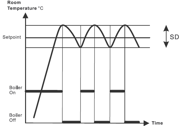
RDH100RF/SET offers both 2-position and PID intelligent learning temperature control, configurable via parameter P01 (control behavior).
2-position control algorithm to switch on and off the heating system within a switching differential (SD) as per the difference between setpoint setting and measured room temperature.
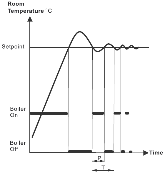
PID intelligent learning control algorithm periodically switches on and off the heating system. The period time (T) and pulse length (P) of the control signal (PWM) are determined by the setpoint and the measured room temperature.
In general, PID control provides more comfort and is more energy efficient than 2-position control.
Control behavior (P01)
The factory setting for control is “PID slow”, ideal for most heating systems. Optimum control can be selected if control does not provide the desired result:
2-position controller with 1 [K] switching hysteresis
2-position, 1 K
- For systems with small capacity that appear slow
- For applications requiring extended runtimes or where frequent switching causes problems
- For difficult control loops where hunting may result
Typical applications
- Dry floor heating systems
- Heat pumps
- Electric heating with contactors
- 2-position controller with 0.5 [K] switching hysteresis.
- For general control situations. Provides better comfort than 1 [K] switching hysteresis.
- Can also be used for difficult control situations.
PID slow
PID control behavior for slow heating systems that require longer minimum On times and a limited number of switching cycles per hour.
Typical applications:
- Wet floor heating systems, oil fired boilers
- Can also be used for all other types of heating applications. (Alternative setting)
| Minimum switch on/off time | > 4 minutes |
| Minimum period | Approximately 12 minutes |
PID fast
PID control behavior for fast heating systems that tolerate a high number of switching cycles.
Typical applications:
- Electric heaters with current valve
- Gas boilers
- Fast thermal actuators
| Minimum switch on/off time | > 1 minute |
| Minimum period | Approximately 6 minutes |
WARNING: Do not use PID fast for oil boilers or electric mechanical actuators!
Backup: When removing the batteries, the setpoints and information required for operating mode changeover are retained for max. 2 minutes.
Commissioning notes
| Parameter | Description | Factory setting | Setting range | Remark |
| P01 | Control behavior | PID slow (4) | 0 = 2P, 1.0 K
1 = 2P, 0.5 K 2 = PID fast 4 = PID slow |
|
| P02 | Maximum temperature range | 30 °C | P03…30 °C | Limit of comfort and economy setpoint |
| P03 | Minimum temperature range | 5 °C | 5 °C…P02 | Limit of comfort and economy setpoint |
| End | Exit parameter setting |
Parameter setting
The parameter setting remains in non-volatile memory and is not erased when the battery is removed. The reset function on the rear of the thermostat reloads the factory settings.
Parameter setting mode
- Press LEARN on the rear for 5 seconds until “P01” appears.
- Press LEARN again and, the parameter value on the second line flashes and is ready for adjustment.
- Adjust the parameter using setting knob.
- Press LEARN once to confirm the setting.
- Rotate the setting knob clockwise to next parameter and repeat steps 2 to 4.
- Exit parameter setting mode by rotating the setting knob clockwise to “End” and pressing LEARN once.
Note: The thermostat automatically exits parameter setting mode one minute after the last action.
Equipment combinations
| Description | Product number | Data sheet *) | |
| Electrothermal actuator (for radiator valves) |  |
STA321 | A6V12986007 |
| Electrothermal actuator (for small valves 2.5mm) | 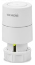 |
STP321 | A6V12986007 |
| Electromotoric actuator | SFA21.. | 4863 | |
The documents can be downloaded from http://siemens.com/bt/download.
Display: The digital display shows the current room temperature and the comfort temperature setpoint. When the heating output is active, the triangle symbol is displayed. 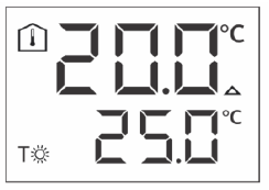
Ordering
When ordering, specify both name and product number, e.g. room temperature controller RDH100RF/SET.
Order valves and actuators as separate items.
Mechanical design
The transmitter consists of 4 parts:
- Plastic housing with digital display containing the electronics, operating elements and built-in room temperature sensor
- Baseplate (mounting base)
- Battery compartment
- Fold-out stand
The housing engages in the baseplate and snaps on. There is a reset button on the rear of the transmitter.
| Elements | 1 |  |
Display of the room temperature in
°C / °F |
| 2 | Indicates a request for heating | ||
| 3 | Temperature setting knob | ||
| 4 |  |
Battery compartment | |
| 5 | Comfort temperature setpoint | ||
| 6 | RF TEST | Indicates RF signal test | |
| 7 | Indicates low battery power; replace batteries |
The receiver is located in a plastic housing with LEDs and buttons.

The transmitter is located in a plastic housing. Two buttons are visible on the rear when removing the baseplate.
OVERRIDE
Override allows for temporarily overriding the active value from the sender. Override responds differently depending on the radio connection (normal or fault).
- Example A: Normal connection between sender and receiver Press the OVERRIDE button to overwrite the value for ca. 14 minutes. The value then returns to the setpoint.
- Example B: Faulty connection between sender and receiver Press the OVERRIDE button to permanently override the value. The value returns to the setpoint after the connection between sender and receiver works again.
RF LED
| RF state | RF LED |
| Power up (first 5 seconds) | Flash RED |
| Power up (after 5 seconds) | RED |
| Press OVERRIDE switch | Flash RED + ORANGE (amber) (4 seconds) |
| Learning period | No LED |
| Software reset | RED |
| RF receive | GREEN |
| No RF within last 25 minutes | RED |
| Manual override (RF receive) | Flash ORANGE |
| Relay state | Relay LED |
| From OUT to ON (first 5 seconds) | Flash ORANGE |
| ON | ORANGE |
| From ON to OFF (after 5 seconds) | Flash ORANGE |
| OFF | OFF |
Mounting
When mounting the transmitter, attach the baseplate first. You need to mount the transmitter on a flat wall. (For details, refer to the separate mounting instructions A6V10974421.)
The transmitter comes with a fold-out stand and may be used as a “mobile” device.
Mounting the receiver does not require a baseplate. Connect the electrical connections first and then fit and secure the receiver in compliance with local regulations. (For details, refer to the separate mounting instructions A6V10974421.)
EMI filter (e.g., KEILS EMI CW4L2-3-R) can be used to reduce EMI disturbance. (For details, see Connection diagram [▶ 14].)
DANGER: Electric shock on directly touches of EMI filter
- Disconnect from power supply before connecting EMI filter.
- Make sure EMI filter is out of reach after installation.
If the reference room contains thermostatic radiator valves, set them to their fully open position.
For commissioning, refer to the operating instructions A6V101035988. Communication of the RDH100RF/SET (transmitter and receiver) is paired ex factory.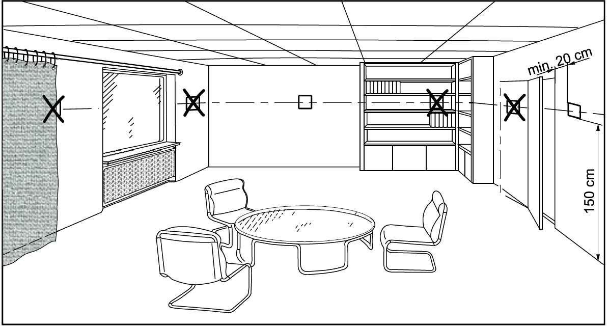
- The devices are suitable for wall mounting.
- Recommended height: 1.5 m above the floor.
- Do not mount the devices in recesses, shelves, behind curtains or doors, or above or near heat sources.
- Avoid direct solar radiation and drafts.
- Seal the conduit box or the installation tube if any, as air currents can affect sensor readings.
- Adhere to allowed ambient conditions.
Change of batteries: If the battery symbol appears, the batteries are almost empty and must be replaced.
Reset
Simultaneously press the TEST and LEARN buttons on the rear of the transmitter to reset it.
Simultaneously press the OVERRIDE and LEARN buttons to reset the receiver. This resets all individual settings to their default values.
Maintenance
The transmitter and receiver are maintenance-free except for the transmitter battery.
![]() Disposal: This symbol or any other national label indicate that the product, its packaging, and, where applicable, any batteries may not be disposed of as domestic waste. Delete all personal data and dispose of the item(s) at separate collection and recycling facilities in accordance with local and national legislation.
Disposal: This symbol or any other national label indicate that the product, its packaging, and, where applicable, any batteries may not be disposed of as domestic waste. Delete all personal data and dispose of the item(s) at separate collection and recycling facilities in accordance with local and national legislation.
For additional details, refer to Siemens information on disposal.
Instructions for the replacement of alkaline batteries
WARNING: Explosion due to fire or short-circuit, even with discharged batteries Risk of injury due to flying parts
- Prevent the batteries from coming into contact with water.
- Do not recharge batteries.
- Do not damage or disassemble batteries.
- Do not heat batteries over 85°C.
WARNING
Leakage of electrolyte: Severe burns
- Handle damaged batteries only wearing suitable protective gloves.
- In case of contact with electrolyte, rinse eyes immediately with plenty of water. Consult a doctor.
Observe the following
- Use only a battery of the same type and from the same manufacturer as a replacement.
- Observe the polarities (+/-).
- The batteries must be new and undamaged.
- Do not mix new and used batteries.
- Store, transport and dispose of the batteries in compliance with local requirements, regulations and laws. Also observe the instructions of the battery manufacturer.
Product Documentation
| Topic | Title | Document ID: |
| Operating | Operating instructions | A6V101035988 |
| Installation | Mounting instructions | A6V10974421 |
| CE declaration | A6V101123354 | |
Related documents such as CE declarations, etc., can be downloaded from the following address: http://siemens.com/bt/download.
Technical data
| Power supply | |
| Operating voltage | DC 3 V (2 x 1.5 V AA alkaline batteries) |
| Battery life | >1 year (with AA alkaline batteries) |
| Sensor inputs | |
| Internal thermistor | 10 kΩ ± 1% at 25 °C |
| Operational data | ||
| PID control: Minimum period
Minimum pulse length |
Slow 4 min
12 min |
Fast 2 min
6 min |
| Setpoint setting range | 5…30 °C | |
| Factory setting comfort setpoint | 20 °C | |
| Environmental conditions | |
| Resolution of settings and displays Setpoints
Actual value displays |
0.5 °C 0.5 °C |
| Operation | IEC 60721-3-3 |
| Climatic conditions | Class 3K5 |
| Temperature | 0…+40 °C |
| Humidity | <90% r.h. |
| Transport | IEC 60721-3-2 |
| Climatic conditions | Class 2K3 |
| Temperature | -25…+60 °C |
| Humidity | <95% r.h. |
| Mechanical conditions | Class 2M2 |
| Storage | IEC 60721-3-1 |
| Climatic conditions | Class 1K3 |
| Temperature | -10…+60 °C |
| Humidity | <90% r.h. |
| Standards, directives and approvals | |
| EU conformity (CE) | A6V101123354 *) |
| RCM conformity to EMC emission standard | A6V101123355 *) |
| Safety class | III as per EN 60950-1 |
| Pollution degree | 2 |
| Degree of protection of housing | IP20 |
| Environmental compatibility | The product environmental declaration (A6V101123359 *) contains data on environmentally compatible product design and assessments (RoHS compliance, materials composition, packaging, environmental benefit, disposal). |
The documents can be downloaded from: http://siemens.com/bt/download.
| Eco design and labeling directives | |||

|
Based on EU Regulation 813/2013 (Eco design directive) and 811/2013 (Labeling directive) concerning space heaters, the following classes apply: | ||
| Application with On/Off operation of a heator | Class I | Value 1% | |
| PWM (TPI) room thermostat, for use with On/Off output heaters | Class IV | Value 2% | |
| General | |
| Weight (including package) RDH100RF/SE |
475 g |
| Color of housing front | Signal-white RAL9003 |
| Housing material | ABS (LCD lens:PC) |
Receiver RCR100/433
| General unit data | |
| Operating voltage *) | AC 230 V +10/-15% |
| Power | <10 VA |
| Frequency | 50…60 Hz |
EMI filter (e.g., KEILS EMI CW4L2-3-R) can be used to reduce EMI disturbance. See Connection diagram [▶ 14].
| Outputs | |
| Switching capacity of relays | |
| Voltage Current | AC 24…250 V
8 (3) A |
|
No internal fuse! External preliminary protection with max. C 10 A circuit breaker required for all cases. |
|
| Switching outputs (LX, L1, L2) | ||
| Relay contacts | Switching voltage | Max. AC 250 V; Min. AC 24 V |
| Switching current | Max. 8 A res., 3 A ind. | |
| At AC 250 V | Min. 10 mA | |
| Contact life at AC 250 V | At 5 A res. | 1 x 10⁵ cycles (guide value) |
| Insulating strength | Between relay contacts and coil | AC 5,000 V |
| Between relay contacts (same pole) | AC 1,000 V | |
| Electrical connections | |
| Connections terminals (via baseplate) For solid wires
For stranded wires |
Screw terminals 2 x 1.5 mm2
1 x 2.5 mm2(min. 0.5 mm2) |
| Environmental conditions | |
| Operation | IEC 60 721-3 |
| Climatic conditions | Class 3K3 |
| Temperature | 0…+45 °C |
| Humidity | <85% r.h. |
| Storage and transport | IEC 60 721-3 |
| Climatic conditions | Class 2K3 |
| Temperature | -25…+70 °C |
| Humidity | <93% r.h. |
| Mechanical conditions | Class 2M2 |
| Standards, directives and approvals | |
| EU conformity (CE) | A6V101123354 |
| Safety class | II as per EN 60 730-1 |
| Degree of pollution | 2 |
| Color | |
| Unit front | Signal-white RAL 9003 |
| Base | Gray RAL 7035 |
| Dimensions | 83x104x32 mm |
Connection diagram
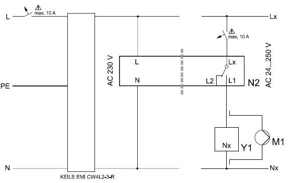
L – N AC 230 V / Lx – Nx AC 24…250 V |
L | Live, AC 230 V |
| Lx | Live, AC 24…250 V | |
| L1 | N.O. contact, AC 24…250 V / 8 (3) A | |
| L2 | N.C. contact, AC 24…250 V / 8 (3) A | |
| PE | Protective ground | |
| M1 | Circulating pump | |
| N | Neutral conductor | |
| Nx | Neutral conductor | |
| N2 | Receiver RCR100/433 | |
| Y1 | Actuating device |
Application examples
 |
|
||
| Wireless room temperature controller with receiver control of a gas-fired wall-hung boiler | Wireless room temperature controller with receiver control of atmospheric gas burner | ||
 |
|||
| Wireless room temperature controller with receiver control of a heating circuit pump (precontrol by manual mixing valve) | |||
| F1 | Thermal reset limit thermostat | N1 | Room temperature controller RDH100RF (Transmitter) |
| F2 | Safety limit thermostat | N2 | RCR100/433 (Receiver) |
| M1 | Circulating pump | Y1 | 3-port valve with manual adjustment |
| Y2 | Magnetic valve | ||

Dimensions
Room temperature controller
Room temperature controller mounting plate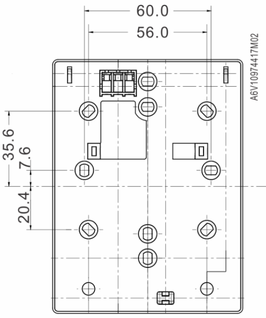
Room temperature receiver with mounting plate
Product History
| Index 1) | Date | Changes |
| ≥C | June 2018 |
|
| Z, A | March 2017 | First release. |
The product index can be found next to the production date on the rear of the device “YYMMDDX”.
© Siemens Switzerland Ltd, 2017
Technical specifications and availability subject to change without notice.
Issued by
- Siemens Switzerland Ltd
- Smart Infrastructure
- Global Headquarters
- Theilerstrasse 1a
- CH-6300 Zug
- +41 58 724 2424
- www.siemens.com/buildingtechnologies
REFERENCE:
DOWNLOAD MANUALS:
SIEMENS RDH100RFSET Room thermostat Product Specifications Guide
OTHER MANUALS:
SIEMENS RDH100RF/SET Room thermostat Operating Instructions
![]()
SIEMENS RDH100RF/SET Room Thermostat Product Specifications Guide
Leave a Reply