seitron TRD03B WIRELESS DIGITAL THERMOSTAT

OVERVIEW
This device is a radio-controlled display thermostat to control the room temperature with the option to choose among different setting modes and related set-point temperatures: Comfort, Economy, Off/Antifrost. The thermostat is set by default to operate in Comfort, Economy and Antifrost modes; it can be adapted to the different installation requirements by modifying the settings and the final user intervention can be restricted, aiming to optimize environment comfort and energy saving. The thermostat can be used in both heating and cooling systems and it is also suitable for floor heating systems
START-UP When activating for the first time, open the thermostat cover, as shown in paragraph ‘INSTALLATION’ in (C of Fig. 6), and insert batteries with the correct polarity. Batteries shall be 1.5V alkaline AA type.
- Bidirectional wireless technology
- Blue backlight display
- Heating/Cooling switching can be controlled on the thermostat or on the receiver
- User limitations to set the Set-point temperatures
- Internal sensor and input plug for remote sensor
- Low battery icon

CONTROLS LAYOUT

Key
Key ‘ ![]() ‘: multifunction key
‘: multifunction key
- Normal operation
- If pressed once shows the set-point temperature.
- If pressed repeatedly increases the set-point temperature.
- In setting mode
- If pressed once shows the set parameter.
- If pressed repeatedly changes the selected parameter (increases the value).
Key ‘ ![]() ‘: multifunction key:
‘: multifunction key:
- Normal operation
- Sets the regulation mode (according to parameter P01):
- Comfort => Economy => OFF/ANTIFROST.
- If pressed for more than 10 seconds, it reverses the operation logic: Heating Cooling.
- In setting mode
- Shows the parameters list
Key ‘![]() ‘: Multifunction key
‘: Multifunction key
- Normal operation:
- If pressed once shows the set-point temperature.
- If pressed repeatedly decreases the set-point temperature.
- In configuration mode
- If pressed once shows the set parameter.
- If pressed repeatedly changes the selected parameter (decreases the value).
DISPLAY INDICATIONS
The meaning of the symbols appearing on the display is given below
Heating/Cooling Set-up
- The thermostat is set by default in heating mode.
- Hold down ‘
 ‘ for 10 seconds to modify the regulation mode.
 - Cooling mode will be set if the thermostat was previously set on heating and the symbol ‘
 ‘ will flash on display for 8 seconds.
 - Heating mode will be set if the thermostat was previously set on cooling and the symbol ‘
 ‘ will flash on display for 8 seconds.
 - The list icon ‘ ‘ Flame indicates that heating mode is on during normal operation; on the contrary, cooling activation is signaled by the Snow icon ‘
Regulation mode set-up
There are 3 ways to set the room temperature that can either be selected by pressing ‘ ‘.
- Comfort: The thermostat sets the room temperature in comfort mode; this is normally the preferred temperature during the daytime.
- Economy: The thermostat sets the room temperature according to the economy mode (this is usually the preferred temperature during night time).
- OFF / Antifrost: Turn off the thermostat; the display will show the text ‘OFF’. If the thermostat was set to heating mode and the antifreeze function is active, the icon ‘
 ‘ will appear on the display; in this case the room temperature will be regulated according to the value set for the antifreeze temperature, in parameter P02. (see paragraph ‘INSTALLER CONFIGURATION’).
 - The thermostat is set by factory default to use OFF, Comfort and Economy modes.
- Through the installer parameter P01 it is possible to deactivate the option to select one or more functions (see the ‘INSTALLER CONFIGURATION’ paragraph).
- Pressing ‘ ‘ cyclically scroll among the different activated setting modes:

- Once a setting mode is set, it remains so until the ‘ ‘ key is pressed again.
- See the ‘INSTALLER CONFIGURATION’ paragraph for further information on how to configure the setting modes.
Set-point Temperature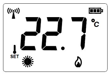
- During normal operation the display shows the room temperature detected and the icon for the selected operating mode. In order to show the relevant set-point temperature press any of the keys ‘
 ‘: the display will show the setpoint temperature and the icon ‘
 ‘ will turn on (thus showing that the value shown refers to the set-point temperature).
- The icon ‘ ‘ turns on along with icon ‘
 ‘ thus meaning that the display is showing the ‘Comfort’ set-point temperature or as an alternative, together with icon ‘
  ‘ thus meaning that the display is showing the ’Economy’ set-point temperature.
- The icon ‘
- Pressing the key ‘‘ results in modifying the current setpoint temperature. By pressing the key ‘ the set-point temperature digits start flashing to point out that the set-point can be changed.
- Pressing the key ‘ ‘ while the display is showing the ‘Comfort’ set-point temperature results in switching to the ‘Economy’ set-point display.
- On the other hand when the display shows the ‘Economy’ setpoint pressing the ‘ ‘ key results in showing the ‘Comfort’ set-point.
- A further pressing of the ‘ ‘ key results in showing the room temperature, as well as after a few seconds of inactivity on the keys
INSTALLATION
- Push, with the help of a screwdriver, the plastic tooth located in the slot on the left side, then lift the plastic cover

- Turn the cover, while pressing it slightly, until it is fully extracted

- Find the best location for the installation (see section ‘RADIO SYSTEM CONFIGURATION), then secure the thermostat base to the wall using the two screw holes with a 60mm. distance (use the screws and/or bolts supplied) after having passed the remote sensor wires (if present) through the rectangular opening

- Insert the batteries (respecting the correct polarity) in the battery compartment use only alkaline, brand-new batteries.

- Connect the remote sensor (if present) using the ‘REMOTE SENSOR’ connector according to the wiring diagram ; then remember to set properly the parameter P09.
 Read the section ‘INSTALLER CONFIGURATION
Close the thermostat as follows:
- Match the two teeth located in the right side of the plastic base with the two slots located on the plastic cover.
- Close the left side of the cover while slightly pressing with a finger, at the same time, the plastic tooth on the left side to the internal (see the arrow in Fig. 8).
- Complete the rotation of the cover until the plastic tooth on the base snaps into the relevant hole of the cover.
- Configure the thermostat: see “INSTALLER CONFIGURATION” paragraph.
Table 1: Installer configuration
Summary of the configuration parameters
EXTERNAL NTC SENSOR
The thermostat features an input (‘REMOTE SENSOR’, B in Fig. 6) to connect an external NTC sensor (optional) alternatively the internal one. The external sensor can be used to measure the room temperature when the thermostat is installed in a position which does not allow a correct room temperature measurement. When the installation requires an installation with a remote sensor, it is necessary to set correctly the parameter P09 and connect a 10 kOhm @ 25°C NTC sensor. If there is any doubt about the type of sensor to be connected, please consult the manufacturer. The thermostat leaves the factory already set to operate with the internal sensor
RADIO SYSTEM CONFIGURATION
- Check on the paragraph ‘COMPATIBILITY WITH BIDIRECTIONAL WIRELESS SYSTEM’, that the receiver to be paired with the thermostat is a compatible one.
- Check if the receiver correctly receives the wireless thermostat signals before installing the latter in the desired position.
- The operation is performed by activating the ‘Test’ function by simultaneously pressing buttons.
- The thermostat displays the icon ‘TEST‘ and continuously transmits switch-on and off controls to the receiver, with a 2 second pause between them, in ‘Test’ mode; every time the thermostat transmits a radio command and only if it receives an acknowledgment from the receiver, the symbol ‘
 ‘ lights up on the display.
 - The ‘Test’ mode can be interrupted at any time by pressing ‘ ‘.
- However, the ‘Test’ mode automatically ends after approx.17 minutes.
- ‘Test’ mode must also be activated to pair a receiver to the thermostat, this procedure allows the devices to exchange and memorize their address which will allow them to recognize each other. In ‘Test’ mode, in addition to the text ‘TEST’, the display will also show ‘nd1’ or ‘Ed1’: nd1: new device 1
- if no receiver has ever been paired. Ed1: existing device 1
- if a receiver has already been paired.
To pair a receiver with the thermostat, activate the pairing procedure on the receiver by pressing the relevant button, after about 10 seconds, if the operation is successful, the thermostat will confirm the pairing with the text dL1: device learned 1 after a few moments the thermostat in ‘Test’ mode will return to display Ed1: existing device 1 the receiver will also confirm the successful pairing, with an alternating red-green-red-green flashing of the LED. Once paired, the receiver will begin to receive the Test commands sent by the thermostat and the relay of its output must continuously switch on and off every 2 seconds, the status is also indicated by the relevant LED. If the receiver has no output relay, the LED will flash green at each reception of the Test command. Observe the LED on the receiver to confirm that the thermostat is communicating correctly with the receiver. Correct communication with the receiver can also be checked on the thermostat: the ‘![]() ‘ symbol lights up on the thermostat display for a few moments each time the thermostat receives an acknowledgment command from the receiver. It is possible to pair more receivers to the same thermostat up to a maximum of 6. During the Test mode, by pressing the
‘ symbol lights up on the thermostat display for a few moments each time the thermostat receives an acknowledgment command from the receiver. It is possible to pair more receivers to the same thermostat up to a maximum of 6. During the Test mode, by pressing the ![]() it is possible to select nd2 (new device 2) to nd6 (new device 6) and perform a pairing procedure for each additional receiver. During the ‘Test’ mode the thermostat will send commands and will receive acknowledgment only from the selected receiver in order to check the correct communication with each single paired receiver. Make sure that the two devices still correctly communicate when positioning the thermostat in the destination area. The output relay always remains on or off if the thermostat is positioned too far from the receiver: if so, we recommend to find a better position, possibly closer to the receiver, and ensure it is not near metal screens or reinforced concrete walls that might weaken radio transmission. The signal quality can be checked with the receiver (see the relative documentation for further information).
it is possible to select nd2 (new device 2) to nd6 (new device 6) and perform a pairing procedure for each additional receiver. During the ‘Test’ mode the thermostat will send commands and will receive acknowledgment only from the selected receiver in order to check the correct communication with each single paired receiver. Make sure that the two devices still correctly communicate when positioning the thermostat in the destination area. The output relay always remains on or off if the thermostat is positioned too far from the receiver: if so, we recommend to find a better position, possibly closer to the receiver, and ensure it is not near metal screens or reinforced concrete walls that might weaken radio transmission. The signal quality can be checked with the receiver (see the relative documentation for further information).
CANCELLATION OF A RECEIVER
In case you have paired the wrong receiver, or need to replace a receiver, it is necessary to cancel the pairing between the thermostat and the receiver. The cancellation procedure takes place by starting the ‘Test’ mode as explained in the previous paragraph, select the receiver to be deleted Ed1-Ed6 with the ![]() keys, press and hold the ‘ ‘ key for 10 seconds, after cancellation the display will show nd1 (nd1-nd6). To avoid malfunctions of the radio system it is important that the receiver to be cancelled is powered and turned on as the receiver must receive the pairing cancellation command from the thermostat.
keys, press and hold the ‘ ‘ key for 10 seconds, after cancellation the display will show nd1 (nd1-nd6). To avoid malfunctions of the radio system it is important that the receiver to be cancelled is powered and turned on as the receiver must receive the pairing cancellation command from the thermostat.
INSTALLER CONFIGURATION
The installer configuration allows to define the thermostat operation to set it to the different kinds of rooms and systems. Hold![]() ‘‘ and ‘ ‘ simultaneously pressed for a few seconds until the ‘
‘‘ and ‘ ‘ simultaneously pressed for a few seconds until the ‘ ![]() ‘ symbol and the word ‘ Con ‘ (configuration) appear on the display, to access the configuration parameter. From this moment, pressing ‘ ‘, will scroll among the different installer parameters identified with ‘P’ and by the parameter number, from P01 to P17.
‘ symbol and the word ‘ Con ‘ (configuration) appear on the display, to access the configuration parameter. From this moment, pressing ‘ ‘, will scroll among the different installer parameters identified with ‘P’ and by the parameter number, from P01 to P17.
The end of configuration is indicated with the word ‘End’. Press ‘ ‘ again to save the configuration and then the thermostat switches to normal operation. At any time, by pressing for a few seconds the ‘ ‘ key, the configuration menu is quit without saving any changes made. While scrolling through the parameters, pressing the ‘![]() ‘ key once, the display shows the current parameter setting. To modify the selected parameter press again the ‘
‘ key once, the display shows the current parameter setting. To modify the selected parameter press again the ‘![]() ‘ keys; holding down the
‘ keys; holding down the ![]() ‘ keys, allows to increase or decrease the value quickly.
‘ keys, allows to increase or decrease the value quickly.
Reset installer configuration
To reset installer configuration, in order to bring all the parameters to factory default values, access the configuration and, when the display shows ‘Con’, simultaneously press![]() for a few seconds until the screen goes back to normal mode.
for a few seconds until the screen goes back to normal mode.
Description of configuration parameters
The installer configuration parameters are shown in table 1 and explained below. Some installer parameters may not be displayed as only the parameters currently required by the configuration are shown (the configuration value of a parameter, may exclude one or more subsequent parameters).
P01: allows to customise the regulation modes that can be selected with the key ‘ ‘. The regulation modes available are Comfort, Economy and OFF: each of these can be enabled or disabled by changing P01. The OFF mode will be replaced by Antifrost mode in case P02 is set with an antifrost temperature.
P02: by this parameter the Antifrost temperature can be set: this will be maintained when the thermostat is turned off. The antifrost temperature can be set in the range 0.5 .. 25 °C or disabled by setting the parameter until the value ‘no’ appears. By factory default this parameter is set at 6 °C.
P03: room temperature offset. The detected room temperature can be corrected by ±10.0 °C with the offset, in order to correct any systematic reading error due to thermostat positioning in unsuitable areas to detect the room temperature. By default the device is set with 0.0 °C offset.
P04: sampling time. To ensure long battery life, the thermostat waits a period of time between one transmission and another. The period can be chosen from 1 to 10 minutes. Therefore it’s normal that the temperature displayed is not immediately updated; moreover for the same reason it can be necessary to wait some minutes (up to the sampling time value) to see the receiver’s output switching. A sampling time of 1 to 3 minutes should be chosen when the heating/cooling system is fast, while with slower heating systems based on radiators or floor heating, even a time of 10 minutes allows excellent accuracy and comfort. In any case, at any time, pressing the ‘ ‘ key forces an update to the receiver. Choosing a longer sampling time will get a longer battery life.
P05 and P06: these two parameters set the temperature range within which the set-point temperature can be chosen when the thermostat is in heating mode. P05 is the lower limit and can be freely set from 5.0 .. 35.0 °C, while P06 is the higher limit that can be set in a range from the lower limit, chosen in P05, up to 35.0°C. Therefore, the widest temperature range is 5 .. 35 °C and can be easily reduced based on installation requirements.
P07 and P08: these two parameters configure the temperature range within which the set-point temperature can be set when the thermostat is in cooling mode, with the same logic of the previous two points. The set-point temperature limits are re-defined upon changing the cooling/heating settings.
P09: NTC sensor configuration.
The thermostat is set by default prepared to operate with the internal NTC (P09= Int). Alternatively to the internal sensor a remote sensor can be wired to the connector ‘REMOTE SENSOR’, shown with B in Fig. 6 and set parameter P10 as ‘Ext’: this way the internal sensor is disabled while the external is enabled. Make sure to use the proper remote sensor type, and respect the maximum wire length allowed
P10: reserved parameter, do not modify.
P11: reserved parameter, do not modify.
P12: hysteresis, represents the amplitude of the hysteresis which will be used for the room temperature regulation.
P13: reserved parameter, do not modify.
P14: reserved parameter, do not modify.
P15: reserved parameter, do not modify.
P16: reserved parameter, do not modify
P17: set-point temperature displayed by default. The thermostat is set by factory default on “no” parameter, so the thermostat shows the detected room temperature, but if this parameter s set on “YES”, the displayed temperature is the set point one, but the room temperature can be temporarily displayed after the set-point temperature is modified. Instead, if the parameter is set on “OnL”, “set-point only”, the thermostat shows only the set-point temperatures (set-point comfort, setpoint economy) and it is not possible to display the room temperature
TEMPERATURE REGULATION
The thermostat regulates the output on the receiver with ON/ OFF type regulation with configurable hysteresis on parameter P12.
DISPLAY BACK-LIGHTING
Switch-on of the display Switch-off is automatic after 20 seconds from last button pressure.
BATTERIES INSERTION/REPLACEMENT
- The display permanently shows the batteries charge state bymeans of symbol ‘ ‘. Batteries are charged to maximum if all three level indicators inside the symbol are on.
- On the contrary, the batteries are drained and must be replaced when the symbol appears completely empty ‘ ‘.
- The symbol ‘ ‘ flashes when the batteries are excessively drained to allow radio transmission.
- For batteries replacement proceed as explained on points 1, 2 and 4 at page 3.
COMPATIBILITY WITH BIDIRECTIONAL WIRELESS SYSTEM
The thermostat works with the following bidirectional wireless technology receivers:
- DA0311: Modbus receiver
TECHNICAL FEATURES
- Power supply: 2 x 1.5V alkaline AA type batteries
- Duration of the batteries: 5 years with P04=10 minutes
- 3 years with P04=3 minutes
- Frequency: 868.450 MHz
- Modulation: GFSK
- Max. RF power transmitted: 1 mW
- Type of antenna: Internal
- Max. distance from receiver: >300 m in free field >50 m in buildings (depending on the building and environment)
- Temperature sensor (internal sensor or remote as alternative)
- Regulation range: 5.0 .. 35.0°C
- Hysteresis: 0.2°C configurable 0.1 .. 5.0 °C
- Type of sensor: NTC 10kohm ±1% @25°C
- B(25/85)=3977
- Resolution: 0.1°C
- Range: -9.9°C .. +50.0°C
- Precision: ±1.0°C
- Maximum length of the wires to the remote sensor: 15 m
- Antifrost: 6.0°C adjustable OFF|0.5 .. 25.0 °C
- Offset: ± 10.0°C. (Default 0.0°C)
- Backlighting switch-off: 20 seconds from last pressing
- Protection rating: IP 30
- Type of action: 1
- Overvoltage category: II
- Pollution degree: 2
- Tracking Index (PTI): 175
- Class of protection against lectric shocks: III
- Rated impulse voltage: 2500V
- Number of manual cycles: 50000
- Number of automatic cycles: unlimited
- Software class: A
- EMC test voltage: 3V
- EMC test current: 35mA
- Distances tolerances fault
- mode ‘short’ exclusion: ±0,15mm
- Ball pressure test temp.: 75° C
- Operating temperature: 0°C .. +40°C
- Storage temperature: -10°C .. +50°C
- Humidity limits: 20% .. 80% RH (non-condensing)
- Enclosure: Material: ABS+PC V0 self-extinguishing
- Colour: Signal White (RAL 9003)
Weight: ~ 115 g
CLASSIFICATION UNDER REG. 2013.811.EC
- Class: I
- Contribution to energy efficiency: 1%
Dimensions

WARRANTY
In the view of a constant development of their products, the manufacturer reserves the right to amend technical data and features without prior notice. The consumer is guaranteed against any lack of conformity according to the European Directive 1999/44/EC as well as to the manufacturer’s document about the warranty policy. The full text of the warranty is available on request from the seller.
REFERENCE:
DOWNLOAD MANUALS:
seitron TRD03B WIRELESS DIGITAL THERMOSTAT User Manual
![]()