seitron TFZ01M Fan Coil Digital Thermostat

INSTALLATION
Carry out the operations below to install the device, while following the images in page 3 to page 7:
- Release the plate attached to the thermostat base by pushing it to the left. This releases the teeth shown in Fig. 1.
- Push the plastic tab in the lower slot using a screwdriver, slightly lifting the cover (Fig. 2).
- Turn the cover, while pressing it slightly, until it is extracted (Fig. 3).
- Fix the plate to the wall, using the two screw seats with center distances of 60 mm or 85 mm (use the supplied wall plugs and/or screws). Pass the wires through the rectangular openings (Fig. 4).

- Connect the thermostat base to the wall plate (pass the wires through the rectangular openings). Align the base holes with the special wall plate teeth, then press the base to the left until the plate’s plastic teeth click (Fig. 5).
Fix the thermostat base to the wall with the supplied screw. - If required, correctly set jumpers JP1, JP2, JP3, JP4 and JP5. Carefully read the “JUMPER SELECTION“ (page 5) and “ELECTRICAL CONNECTIONS“ paragraphs.
- Perform the electrical connections following the connection diagram in Fig. 7 and the possible variants in Fig. 8. Carefully read the “ELECTRICAL CONNECTIONS“ paragraph.
- Perform the following operations to close back the thermostat:
- Position the two teeth on the upper part of the cover in the special notches.
- Turn the cover and push the plastic tab inwardly on the lower part of the base (see the arrow in Fig. 9). Press it so that the plastic fixing tab inside the special hole clicks.
WARNING
- The delivery water sensor must be installed in a way that it can acquire the correct water temperature even in case the flow is stopped by the valve itself.
- Wiring the same remote temperature sensor to more than one controller is not allowed.
- All remote sensors, bimetallic contact and window contact must have a galvanic insulation against earth as well as against the mains power.
- In case precending two directions are not respected an irreversible product damage can follow.
- All remote sensors, bimetallic contact and window contact must be double insulation (or reinforced insulation) rated in case they are accessible to people.
- In case the reinforced insulation of the preceding point cannot be obtained, power the regulator with a 24V~ low voltage (yet in full compliance with the safety standards).
- While checking with a multimeter valve outputs (terminals from 9 to 12), it will not be possible to see the commutation correctly due to filters mounted with TRIAC outputs. It is necessary to
- wire a load to the output (valve) to correctly show the commutation status.
- The appliance must be wired to the electric mains through a switch capable of disconnecting all poles in compliance with the current safety standards and with a contact separation of at least 3 mm in all poles.
- Installation and electrical wirings of this appliance must be made by qualified technicians and in compliance with the current standards.
- Before wiring the appliance be sure to turn the mains power off.
JUMPER SET-UP

PERFORM THE ELECTRICAL CONNECTIONS FOLLOWING THE MOST APPROPRIATE CONNECTION DIAGRAM (FIG. 8, 9, 10, 11) AND THE POSSIBLE VARIANTS (FIG. 12, 13). CAREFULLY READ THE “ELECTRICAL CONNECTIONS“ PARAGRAPH.
WIRING DIAGRAM
EXPLANATION
- JP2: 230/24V~ selection
- V HEAT: 0..10V heating signal output
- V COOL: 0..10V cooling signal output
- V FAN: 0..10V fan signal output
- HEAT: U Heating valve output
- COOL: Cooling valve output
- E/I: Remote input to activate “centralized Heating/Cooling“ function(1)
- RDC: Remote input to activate the “Economy“ function(1)
- M: Fan motor
- ECM: M Electronically commutated motor
- Sc: 0..10V Floating actuator
- S.M.: Supply water sensor
- S.A.: Room sensor
- CF: Remote input to activate the “Window contact“ function(1)
- RS: Connector for remote room temperature sensor connection. See “Electric connections“
 : Isolamento rinforzato – Reinforced insulation
WARNING! The C23 parameter of the function associated to terminal 8 can be changed.
Notes The C17, C18, and C19 parameters of the function associated to the input can be changed.
- Fig 8: Wiring diagram for 2 on/off 230V~ actuators in 4 pipes system and proportional fan drive.
- Fig 9: Wiring diagram for 2 on/off 24V~ actuators in 4 pipes system and proportional fan drive.

- Fig 10: Wiring diagram for two 0..10V 24V~ actuators in a 4 pipes system and one 230V three speeds motor.
- Fig 11: Wiring diagram for a 0..10V 24V~ actuator for an electric heater integration system and driving of a proportional fan motor.

OUTPUT DRIVING
The scheme shows the valve control in a 4-pipes unit with the neutral zone. In the diagram, it is assumed that outputs are configured for proportional direct action (0..10V) and that any integrative action is not taken into account. Likewise a 2-pipe system valve output (heating valve output) would be driven at the same way, in this case Ts (set-point temperature) would coincide with Ts hea when in heating mode and Ts coo when in cooling mode.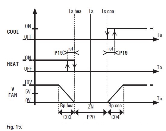
The scheme shows the valves control in a 4-pipes unit with neutral zone. Similarly, the heating valve output (HEAT) in a 2-pipes system will be controlled in the same way. In this case, the Ts (setpoint temperature) will correspond to Ts ris when in heating mode, and to Ts raf when in cooling mode. The scheme shall not consider the integrating time action, if any, and shall suppose the fan proportional output (V FAN) is configured for the direct action (P05=0) and 0..10V signal (C15=0; C16=100).
The fan proportional output is always turned off (0V) when the valve output, COOL or HEAT, is off (not shown on the scheme).
INTRODUCTION
This embedded electronic regulation device is a digital thermostat to control the temperature in rooms heated or cooled with fan coils. It provides continuous proportional control over the valves and speed of the fan on the 0..10V outlets in order to control the room’s temperature in a more convenient way.
The device is also fitted with three ON/OFF relay outputs that can be used to control a fan with three-speed settings or two ON/OFF actuators. The room temperature can be detected by the internal or remote probe (optional feature).
DESCRIPTION OF CONTROLS
Key “![]() “ (On/Off)
“ (On/Off)
This button is used to turn on and off the controller: when the controller is turned off the display does not show the temperature, yet some symbols could still be turned on to show the active outputs.
If the thermostat is configured in the “Economy“ function (P17), the “![]() “ button activates/deactivates this status according to the following diagram:
“ button activates/deactivates this status according to the following diagram:![]()
“![]() “ button (Speed)
“ button (Speed)
This button changes the set fan speed. When the “![]() “ button is pressed, the fan speed changes according to the following cycle:
“ button is pressed, the fan speed changes according to the following cycle:
where 1, 2 and 3 mean the three fixed fan speeds meanwhile AUT means the automatic fan speed.
More precisely 1 means the lowest speed, 2 the medium speed and 3 the fastest. Therefore when the controller is set on one of the three mentioned speeds, the fan will be activated when necessary at that (fixed) speed. Whenever the automatic speed is set instead, the controller will activate the fan at a speed as much high as the difference between the desired room temperature against the current one.
Key “![]() “ (Menu)
“ (Menu)
This button is used to change the display readout mode: when depressed once it makes the display show the set-point temperature.
In case the controller is configured to show the delivery water temperature, this value will be displayed with a further button depression. When changing the readout, the controller informs the user about the temperature shown according to the following table:
Repeatedly press the button to cyclically display the various temperatures. When inactive for a few seconds the display returns to room temperature.
![]() buttons
buttons
These buttons set the desired room temperature (set-point) and the configuration parameters. If ![]() are pressed during normal operation, the set-point temperature is displayed, along with the new set value.
are pressed during normal operation, the set-point temperature is displayed, along with the new set value.
Even in this case, after a few seconds of inactivity the display readout returns to the room temperature.
DISPLAY VIEW
The thermostat is equipped with an LCD display that shows temperature and settings.
Symbols displayed:
The symbols that can be shown on the display are described in the following table:


Some symbols on the display show the status of the output: fan, valves or other connected loads.
The “fan speed“ symbols show fan status: all off when fan is off; all lit when fan is on, according to the following indications:
Symbols “![]() “ and “
“ and “![]() “ indicates the status of the valve outputs which is different depending on the type of system.
“ indicates the status of the valve outputs which is different depending on the type of system.
Two pipes system:
 : heating mode, valve open
 : cooling mode, valve open
Four pipes system:
- : heating valve open
- : cooling valve open
Electric heater system:
- : heating mode, electric heater on
- : cooling mode, cooling valve open
Integrating electric heater system:
- : heating mode, valve open
- : cooling mode, valve open
 : heating mode, electric heater on
Heat pump system:
- : reversing valve in heating
- : reversing valve in cooling
 : compressor on
Symbols can also be flashing, to explain that the relevant output should be turned on, yet it is temporarily disabled by another function.
As an example, outputs are disabled in the following situations:
- The cut-off thermostat is inhibiting the fan;
- Window contact suspends the temperature regulation
WIRINGS
This controller can be powered either with 230V~ or with 24V~. The thermostat is factory set at 230V~, with jumper in position JP1, with frequency at 50Hz, with jumper in position JP4. To select 24V~ supply, move jumper JP1 (Fig. 6) to position JP2 (Fig. 6). To select 60Hz frequency move jumper to JP4 (Fig. 6) to position JP3 (Fig. 6).
As shown in the wiring diagrams, supply terminals are L and N. If you have a 230V power supply, the live and neutral must be respected An input is available on terminal 3 for centralised heating/cooling selection. An input is available on terminal 4 to activate “Economy” mode.
A window contact can be connected to terminals 14 and 16.
Note: there are limitations for window contact use. Carefully read the paragraph “ATTENTION”. The function of the input terminals 3, 4 and 16 can be changed through parameters C17, C18 and C19. Signals to terminals 3 and 4 can be connected terminals 3 and 4 of other thermostats in the same building (centralised Heating/Cooling function). RS connector, or alternatively terminals 14 and 15, can be used to connect an external room temperature sensor. Change configuration to select external or internal sensor use.
Terminals 13 and 14 is an input to connect different types of sensors for special functions: connect a delivery temperature sensor for the “changeover“ and/or “cut-off thermostat” function, or connect a bimetal thermostat with “cut-off thermostat” function. Change configuration to select which type of sensor to use (P08). The device is suitable to control both an electronic fan motor (EC motor) and a three speeds fan motor. Use parameter P05 to decide whether to use the 0-10V proportional output for an EC motor or the three relay outputs for a three speeds motor. If the proportional output is used, the 0-10V signal will be available on terminal 11, while the reference ground on terminal 12. Connect the EC motor as shown in Fig. 13a. If the three relay outputs for a three speeds motor are used, the outputs are available on terminals 6, 7 and 8, while terminal 5 is the relays common. Connect the three speeds motor as shown in Fig. 13b.
The fan motor outputs, terminals 5 to 8, are voltage free and insulated with reinforced insulation towards the other circuits of the thermostat. Therefore, a thermostat can be supplied with SELV low voltage (24V~), while controlling a high voltage fan (230V~), as shown in Fig. 10. In this case, 24V~ SELV and 230V~ cables must be separated in accordance with current standards.
In particular, it is necessary to secure the two groups of cables with cable ties separating the SELV wires from the others. This is required to avoid that the insulation to SELV is reduced in the event of a wire accidentally disconnects.
WARNING
- Installation and electrical wirings of this appliance must be made by qualified technicians and in compliance with the current
standards.
The device can control one or two 0..10V proportional actuators or one or two ON/OFF actuators. The outputs for the ON/OFF actuators are only available when there is a proportional motor, i.e. when the relay outputs are not used to control the three speeds motor.
The heating 0..10V proportional output is available on terminal 9, while the cooling output on terminal 10, Fig.12d. For two-pipes systems, a single valve is used both for heating and cooling and in this case the control signal will be the heating one available on terminal 9, Fig.12b.
For all 0..10V signals (valves and fan), the reference ground is available on terminal 12. Please note that the ground is electrically connected to the power terminal N (Neutral).
To connect 24V actuators, follow diagrams in Fig.9 and 10, while follow Fig. 8 for 230V actuators. Usually 0..10V actuators only have 3 connection wires, as the ground of the input signal is internally connected to one of the two power-supply wires (Neutral). In this case there is no need to connect terminal 12 (output signal ground), as the actuator uses the Neutral power terminal as ground. Make sure the latter is connected to terminal N.
When using ON/OFF valves, the heating output is available on terminal 6 and the cooling output on terminal 7 Fig. 12c.
In the case of two-pipes systems, only one valve needs to be connected to the heating output. Connect it as shown in Fig. 12a.
It is possible to manage systems with two different kinds of valves for heating and cooling, for instance ON/OFF heating output and 0..10V proportional cooling output.
If the system has an electric heater for integrations or to replace the heating valve, connect according to diagrams in Fig. 12e or Fig. 12f.
TECHNICAL FEATURES
- Power supply: 24/230V~ 50/60Hz
- Power absorption: 1,2W
Room temperature
- Regulation range: 5.0 .. 35.0 °C (configurable)
- Sensor type: NTC 10kΩ @ 25°C ±1%
- Precision: ± 1°C (± 1,8°F)
- Resolution: 0,1°C (0,1°F <100°F)
- Display temp. range: 10°C .. +50°C (14°F .. 122 °F)
- Differential: adjustable 0,2°C (0,4°F)
Supply pipe temperature
- Sensor type: NTC 10kΩ @ 25°C (77 °F) ±1%
- Precision: ± 1°C (± 1,8°F)
- Resolution: 1°C (1,8°F)
- Display temp. range: 0°C .. 99°C (32°F .. 210 °F)
- Differential: 2°C (4°F)
Proportional outputs
- Signal range: 0..10V

- Signal precision: ±0.26V
- Minimum actuator impedance:
- 1 0..10V output: 1850 Ohm
- 2 0..10V outputs: 3700 Ohm
- 3 0..10V outputs: 5550 Ohm
- Relay contact capacity: 3(1)A 250V~
- Remote sensor (optional): NTC 10kΩ @ 25°C (77 °F) ±1%
- Protection grade: IP 30
- Type of action: 1
- Overvoltage category: II
- Pollution degree: 2
- Tracking index (PTI): 175
- Class of protection against electric shock: II
- Rated impulse voltage: 2500V
- Number of manual cycles: 50000
- Number of automatic cycles: 100000
- Software class: A
- EMC test voltage: 230V~ 50Hz
- EMC test current: 34mA
- Distances tolerances fault mode ‘short’ exclusion: ±0,15mm
- Ball pressure test temperature: 75°C (167 °F)
- Operating temperature: 0°C .. 40°C (32°F .. 104°F)
- Storage temperature: -10°C .. +50°C (14°F .. 122°F)
- Humidity limits: 20 .. 80% RH (non condensing)
- Case:
- material: ABS + PC V0 self-extinguishing
- color: signal white (RAL 9003)
- Size: 132 x 87 x 23,6 mm (W x H x D)
- Weight: ~265 g
CLASSIFICATION UNDER REG. 2013.811.EC
- Class: V
- Contribution to energy efficiency: 3%
WARRANTY
In the view of the constant development of their products, the manufacturer reserves the right for changing technical data and features without prior notice. The consumer is guaranteed against any lack of conformity according to the European Directive 1999/44/EC as well as to the manufacturer’s document about the warranty policy. The full text of warranty is available on request from the seller.
APPENDIX
HEATING/COOLING SELECTION
Heating or cooling modes are selected by keeping the ![]() “menu“ button depressed for some seconds, until the display shows one of the following texts which indicates the current mode:
“menu“ button depressed for some seconds, until the display shows one of the following texts which indicates the current mode:
- HEA : Heating mode
- COO: Cooling mode
Then, by pressing the ![]() or “
or “![]() “, the user can change the desired mode, cycling between heating and cooling. Depressing any of the other buttons results in saving the choice and quitting the menu.
“, the user can change the desired mode, cycling between heating and cooling. Depressing any of the other buttons results in saving the choice and quitting the menu.
When the thermostat is configured for automatic or centralised heating/cooling selection, the selection cannot be manually changed and if tried, the display shows the flashing “![]() “ icon.
“ icon.
SUPPLY PIPE SENSOR
This controller features an input for the delivery water temperature sensor: when this sensor is installed the controller can automatically understand whether it should be working in “cooling“ mode or in “heating“ mode: this function is called “water temperature changeover”.
The water temperature is also used to perform the “cut-off thermostat“ function.
Alternatively, a bimetallic thermostat can be wired to the input to get the “cut-off“ function.
EXTERNAL INPUTS – TERMINALS 3, 4 AND 16
The thermostat has three external inputs that can be associated to different functions through parameters C17, C18 and C19.
Signals to terminals 3 and 4 can be connected to terminals 3 and 4 of other thermostats in the same building for centralized functions. The signal on terminal 16 cannot be connected to other thermostats.
Functions that can be associated to the inputs are:
“Centralised Heating/Cooling“ function:
When installations have multiple thermostats in a single building, the centralized inputs of each thermostat can be connected together and controlled by the central heating room.
This way the central heating room determines whether the thermostats must operate in the heating or cooling mode.
“Economy“ function:
The input activates/deactivates the economy mode (see the “Economy function“ paragraph). This function can be associated with the following icon: “![]() “. The thermostat is sensitive to the input status changes
“. The thermostat is sensitive to the input status changes
and not to the level, so it is always possible to change the economy status with the “![]() “ button (if enabled).
“ button (if enabled).
“Regulation stop“ function
The input can suspend or reactivate room temperature regulation. When temperature regulation is suspended the fan is stopped, the valves remain closed and the relevant symbols on the display will flash. This function can be associated with one of these icons: “![]() “ or ““
“ or ““![]() “ 0“ “
“ 0“ “![]() “. When an input is configured for the “regulation stop“ function and the “
“. When an input is configured for the “regulation stop“ function and the “![]() “ icon, the “window contact“ function is performed. Connecting a window contact to the input, when the window is open the “
“ icon, the “window contact“ function is performed. Connecting a window contact to the input, when the window is open the “![]() “ icon will appear on the display and the temperature regulation will be suspended.
“ icon will appear on the display and the temperature regulation will be suspended.
Note: there are limitations for window contact use. Carefully read the paragraph “ATTENTION”.
“Thermostat ON / OFF“ function
The input turns the thermostat on or off, like pressing the “![]() “ button. Since the thermostat is sensitive to input status changes and not to the level, so it is always possible to change the on/off status with the ““ button (if enabled).
“ button. Since the thermostat is sensitive to input status changes and not to the level, so it is always possible to change the on/off status with the ““ button (if enabled).
“Motor alarm“ function
The input lights the “![]() “ icon on the display. When the alarm is active, the electric heater output will be cut off.
“ icon on the display. When the alarm is active, the electric heater output will be cut off.
“Electric heater alarm“ function
When the alarm is activated “![]() “ + “
“ + “![]() “ symbols flash on the display and the electric heater output will be cut off. The electric heater safety thermostat can be connected to this input.
“ symbols flash on the display and the electric heater output will be cut off. The electric heater safety thermostat can be connected to this input.
“Dirty filter“ warning function
the input activate the dirty filter warning, the “![]() “ filter icon blinks on the display.
“ filter icon blinks on the display.
“Motor rpm control” function
The function is used to monitor the fan rotation by measuring the motor’s rpm. The function can be configured only on input 16. The motor rpm sensor must be connected to terminal 16. When the fan is on, the thermostat ensures the motor runs and does not get stuck. It ensures the signal frequency is between 1 and 255 commutations per second. In the event of an error, the “![]() “ icon appears on the display and the electric heater output will be disabled, if there is one.
“ icon appears on the display and the electric heater output will be disabled, if there is one.
OUTPUT 8
The thermostat can control output 8 to perform a special function. The special function is configured on parameter C23 and table 6 shows the functions that can be configured.
Output 8 is not available when the three relays for three speeds motor are used and when the integration electric heater system is chosen.
Functions that can be configured are:
- Fan logic
The output is active when the proportional fan is on, regardless of the speed. - Valve logic
The output is active when the valve is opened. In case of 4 pipes system, the output is active when one of the two valves is opened. - ON/OFF logic
- The output is active when the thermostat is turned on.
Economy logic
The output is active when the thermostat is in economy mode or is turned off. - Heating/cooling logic
The output is active when the thermostat is in heating mode. - Input status repetition
The output repeats the status of an input 3, 4 or 16. The output is active when the input is closed.
CONTROL OF 0..10V PROPORTIONAL OUTPUTS
It is possible to connect several actuators to the same 0..10V output, however it is necessary to make sure the output is not overloaded. Ensure that the impedance of the group of actuators does not drop below the minimum impedance the thermostat can control (see “Technical features” section).
The thermostat constantly controls the 0..10V outputs and if it detects an overload, it reports the anomaly on the display by turning on the “![]() ” icons in the event of an issue on the heating or cooling 0..10V valve output and the “
” icons in the event of an issue on the heating or cooling 0..10V valve output and the “![]() “ icon in the event of an issue on the 0..10V fan output. If there is a problem affecting the fan output, the electric heater output is disabled in the electric heater and integrating electric heater systems.
“ icon in the event of an issue on the 0..10V fan output. If there is a problem affecting the fan output, the electric heater output is disabled in the electric heater and integrating electric heater systems.
TEMPERATURE ACQUISITION
- This controller acquires both the room temperature and the delivery water temperature in the fan-coil exchanger with NTC type sensors.
- The room temperature is acquired and displayed with the above mentioned resolution in the range -10°C .. +50°C.
- The controller features an internal temperature sensor and also an input for a remote sensor is also available.
- The selection between internal or remore sensor is done through parameter P10 in the “installer configuration“.
- The supply water temperature in the fan-coil is acquired through a remote sensor and can be displayed with 1°C resolution in the 0°C .. 99°C range.
- The delivery water sensor does not have to be installed in case the system does not require it. To enable delivery water sensor related functions, see the “Cut-off temperature function“ section.
- In case the room or water temperature falls outside the operating range, the display shows “Or“ (out of range). In case the sensor is faulty as an open or a short circuit, the display shows “EEE“ (error): in this situation, functions which need the temperature are not performed.
CUT-OFF TEMPERATURE FUNCTION
The cutoff temperature function is used to inhibit the fan operation whenever, in heating mode, the delivery water is not hot enough. In order to accomplish this function a delivery water sensor must be wired, alternatively, a bimetallic thermostat can be wired to the same terminals. In case the delivery water sensor is used, the “water hot enough” threshold is defined on parameter P22. In case this function is not needed, parameter P22 can be set to a very low value (0).
In case a bimetallic thermostat is used for this function, parameter P07 must be set to the value “2“: in this case the fan operation will be enabled only when the bimetallic contact is closed.
When this type of bimetallic thermostat is used the water temperature cannot be displayed, nor the automatic changeover function can be performed. Please refer to the section “Installer Configuration“ to set the parameters related to the above described functions.
The cut-off temperature function is also available in cooling mode. In this case the fan operation is inhibited when the water delivery is not sufficiently cold, according to the threshold defined on parameter P23. In case this function is not needed, parameter P23 can be set to a very high value (99).
When the delivery water temperature is not sufficiently hot or cold as per P22 and P23 thresholds, the display shows the “![]() “ icon. The fan is inhibited and the fan speed symbols flash.
“ icon. The fan is inhibited and the fan speed symbols flash.
ELECTRIC HEATER SYSTEM
The thermostat can be configured (P01=2) to manage a system with an electric heater for heating the room and a valve that regulates the cool water for cooling the room. Follow the wiring diagram in Fig. 8 e and f. In this type of system it is suggested to set a delay on the fan switch-off on P21, so that when the electric heater is switched off, the fan keeps running to cool the heater down.
In this type of system it is possible to have a neutral zone regulation setting the automatic heating/ cooling selection (P02=1).
In case the cut-off temperature function is used in this system, the fan will never be inhibited while in heating mode.
INTEGRATING THE ELECTRIC HEATER SYSTEM
This regulator can be configured (P01=3) to manage a special plant type featuring two heating systems: one with a hot water flow controlled by a valve, the other with an integrating electric heater. In this mode the regulator is only driving one valve wired at the cooling output to manage a special plant type featuring two heating systems: one with a hot water flow controlled by a valve, the other with an integrating electric heater. In this mode the regulator is only driving one valve wired at the cooling output and one integrating electric heater wired at the heating output.
The relevant wiring diagram is in Fig. 12e and Fig. 12f. The valve is driven as in a two pipes system: according to the heating or cooling setting of the controller, the relevant flow of hot or cool water is managed.
The electric heater is turned on as an additional (integrating) heat source whenever, in heating mode, the room temperature falls below the set point temperature by a Δ setpoint that can be configured in parameter C21.
In cooling mode it is possible to have a neutral zone regulation by setting a neutral zone width greater than zero on P20. In this case cooling is achieved by activating the valve, while heating by activating the electric heater.
In this type of system it is suggested to set a delay on the fan switch-off on P22, so that when the electric heater is switched off, the fan keeps running to cool the heater down.
When the fan motor is proportional driven, for the same purpose of cooling the heater down, it is possible to set on parameter C14 a minimum speed that will be maintained when the electric heater is on.
In case the cut-off temperature function is used in this system, the fan will never be inhibited while in heating mode, since the electrical heater will be turned on in advance instead.
UNDERFLOOR HEATING SYSTEMS WITH FAN COIL FOR COOLING
The thermostat can be configured to manage a special system which uses different means of temperature conditioning depending on whether heating or cooling is needed in the room.
For example, in the summer season a fan coil can be driven for room cooling by controlling the fan and the cold valve, while in winter season it could only drive the hot valve of the underfloor system always keeping the fan coil fan off. The thermostat can receive information on the summer/winter status directly from the heating system on an input (3 or 4), in this way there will be an automatic management of the seasonal changeover, with an automatic recall of the climate mode and setpoint of the respective season.
To configure this type of system, set P01 = 1 e P03 = 4.
ECONOMY FUNCTION
The “Economy“ function allows to temporary set an energy saving mode through a reduction of the actual setpoint temperature by a step (configurable) when in heating mode, or increasing it by the same step when in cooling mode. The value for this reduction step is set with parameter P18: when this is set to 0.0 the Economy function is actually disabled. The Economy mode is activated by the “![]() “ button, as described in the “Description of controls” section. The Economy mode can be remotely activated in centralised mode, even for multiple thermostats, using the inputs to terminals 3 or 4 (see parameters C17 and C18). Since the thermostat is sensitive to signal status changes and not to the level, use the “
“ button, as described in the “Description of controls” section. The Economy mode can be remotely activated in centralised mode, even for multiple thermostats, using the inputs to terminals 3 or 4 (see parameters C17 and C18). Since the thermostat is sensitive to signal status changes and not to the level, use the “![]() “ button to change the activation status of the Economy function, even when it is forced by the centralised signal.
“ button to change the activation status of the Economy function, even when it is forced by the centralised signal.
When the Economy function is activated (“![]() “ icon on), the fan speed is limited to the first or to the value set on parameter C11 for fans with a proportional control.
“ icon on), the fan speed is limited to the first or to the value set on parameter C11 for fans with a proportional control.
DIRTY FILTER WARNING FUNCTION
Fan-coils and other devices including a fan are often equipped with a filter for the air in the suction path, which needs a periodical maintenance and cleaning or replacement. This regulator can warn the user when the maintenance has to be made, provided the “Dirty filter warning“ function has been enabled. The function is activated by setting the time-to-maintenance on parameter P25. The thermostat will count the fan operation time and when the threshold set in P25 (per 100 hours) is reached, the “![]() “ filter icon blinks on the display. Once the filter has been cleaned, to reset the warning and the time counter keep the “
“ filter icon blinks on the display. Once the filter has been cleaned, to reset the warning and the time counter keep the “![]() “ button pressed for 10 seconds, until the “
“ button pressed for 10 seconds, until the “![]() “ filter icon disappears from the display.
“ filter icon disappears from the display.
TEMPERATURE REGULATION
This device can drive in a proportional way both valves and fan in order to control room temperature with the highest comfort and energy saving. Nonetheless each different environment needs a different set for some parameters in order to get an accurate regulation.
Parameters responsible for the regulation accuracy are:
- Proportional band: C03 and C04
- Integral time: C05 and C06
For each of the settings two parameters are available, because the user is allowed to set different values for heating and cooling mode. The proportional band in °C or °F is the difference between the setpoint value and room temperature that ensures the valve is fully opened by the regulator and/or turns on the fan at the maximum speed.
The narrower the proportional band, the fastest is the regulator to counteract temperature variations in the room. Yet a too “narrow“ value for this parameter can result in room temperature oscillations or system instability.
A too “wide“value could result in the impossibility to reach the setpoint temperature in the room. When the integral time is set to zero, no integral action is made and therefore the regulation is purely proportional (P type). When an integral time different from zero is set the resulting regulation is made of a Proportional plus an Integral action (P + I type).
The smaller the integral time, the greater the influence of the integral action and vice-versa: with a greater integral time the resulting integral action is softer. A too soft or null integral action could result in the impossibility to reach the setpoint temperature, meanwhile, a too strong integral action could possibly generate oscillations in the room temperature. It is necessary to adjust these parameters according to the actual environment in which the regulator is installed to get the best regulation accuracy.
The proportional control of the valves can only take place when they are controlled by the 0..10V outputs. Proportional control cannot take place if using ON/OFF valves, they will be driven either always ON or always OFF with hysteresis set on parameter P19.
The fan will be proportional driven only when it is set in automatic speed (AUTO). The fan speed will be proportional regulated (P + I) even when the fan motor is a three speeds one.
The distance between the three-speed stages is calculated dividing by three the proportional band and rounding down. For example if the proportional band is 2°C (35,6 °F), the distance between stages will be 0.6°C (33,08 °F).
INSTALLER CONFIGURATION
Installer configuration defines the thermostat operation and allows to adapt it to the different types of plants and systems. To access the configuration menu, simultaneously press the “![]() “ e “
“ e “![]() “ buttons for a few seconds until “COn” (configuration) appears on the display.
“ buttons for a few seconds until “COn” (configuration) appears on the display.
Once entered in configuration menu, pressing “![]() “ scrolls through the various parameters, identified with P and the parameter number, from P01 to P25. The configuration end is displayed with “End”. Press “
“ scrolls through the various parameters, identified with P and the parameter number, from P01 to P25. The configuration end is displayed with “End”. Press “![]() “ again to save the configuration and and return to normal operation.
“ again to save the configuration and and return to normal operation.
Press the “![]() “ button, at any time, to exit from the configuration menu without saving the changes.
“ button, at any time, to exit from the configuration menu without saving the changes.
When scrolling the parameters pressing button “![]() “ or
“ or ![]() displays its current value.
displays its current value.
To change the value, when it is displayed, press button ![]() .
.
To prevent unauthorised access to the configuration remove the internal jumper (JP5) shown in Fig. 6. Any attempt to access the configuration will display the flashing “![]() “ icon.
“ icon.
The installer configuration consists of two lists of parameters:
- main parameters P01 to P24 (table 1)
- extended parameters C01 to C19 (table 2)
The extended parameters C01-C19 allow an advanced thermostat configuration.
When the display shows “COn“ at configuration start or “End“ at configuration end, press the “![]() “ button to access the extended parameters.
“ button to access the extended parameters.
INSTALLER CONFIGURATION RESET
In order to reset the installer configuration, so that all parameters are reset to the factory default values, enter the configuration mode by holding down the keys “![]() “ and “
“ and “![]() “ until the display shows “Con”, then hold down the two keys
“ until the display shows “Con”, then hold down the two keys ![]() for a few seconds, until the display returns to the usual screen.
for a few seconds, until the display returns to the usual screen.
DESCRIPTION OF MAIN CONFIGURATION PARAMETERS
The main installer configuration parameters are shown in table 1 and explained below.
P01: System type selection.
- 2 pipes system: when configured for a two-pipe system the controller drives one valve only, wired at the “heating“ valve terminals, both when heating and when cooling, as the same valve is going to control either hot or cool water flow.
See the wiring diagram in Fig. 12c and Fig. 12d.
In case of a two-pipes system without the valve, and therefore with no wirings at the valve output terminals, make sure to set parameters P03 and P04 to “fan control“ in order to get an effective regulation. - 4 pipes system: when configured for a four-pipe system the controller drives both valves outputs in order to activate either the hot water or the cooling one according to the actual requirements of the controlled environment.
See wiring diagram in Fig. 12c and Fig. 12d. - Electric heater system: the regulator is configured to control a system equipped with an electric heater: see the section “Electric heater system” for more details.
- Integrating electric heater system: the regulator is configured to control a system equipped with an electric heater: see the section “Integrating electric heater system“ for more details.
P02: This parameter sets the way how the controller switches from the cooling mode (summer) to the heating mode (winter) and vice versa.
The switching can be either manual or automatic:
- Manual: The user manually sets the heating or the cooling mode.
- Automatic: The controller automatically switches from the heating to the cooling mode or vice-versa.
This automatic operation is different according to the system type as set with parameter P01.
In case of a 4-pipes system, an electric heater or heat pump system he thermostat operates with a neutral zone. Therefore it activates heating or cooling according to the set point temperature. In case of a 2-pipes system or an “integrating electric heater” system, the controller operates a changeover according to the delivery water temperature.
When the delivery water temperature is low (that is below the threshold set with parameter C01) the controller switches to cooling mode.
On the opposite side, when this temperature is high (that is above the threshold set with parameter C02) the controller switches to heating mode. In case the supply temperature is neither too low nor too high the operating mode is kept unchanged, and can be manually changed. When the delivery water sensor is not installed or it is not properly working, no automatic selection is performed and only the manual switching is allowed. - Remote selection: In a building with several regulators all inputs can be wired together for a remote selection coming from the central heating room. On C11, C12 and C13 parameters it is possible to choose the input and the mode (normal or reversed) to be associated to the “remote heating/cooling“ selection.
In Fig. 7 is shown a wiring example for a remote heating/cooling selection.
P03 and P04: these parameters set which outputs are controlled.
When in heating mode parameter P03 is used, when in cooling mode P04 is used instead, in this way you can choose different means of temperature conditioning depending on the season.
Each parameter defines whether the thermostat must regulate the temperature by acting on the valve or on the fan or on both.
- If you choose to regulate only with the valve, the fan will be always on even after temperature has reached the setpoint, or you can choose to keep the fan always off.
- If you choose to regulate only with the fan, the valve will be always open even after temperature has reached the setpoint, or you can choose to keep the valve always closed.
- In systems with electric heater or heating pump these parameters cannot inhibit the valve outputs because these outputs are driven according to the specific system type.
P05:
This parameter tells the thermostat which kind of fan motor need to be driven: an EC motor on the 0-10V proportional output or a three-speeds fan motor on the three relay outputs.
Also it is possible to select a “reverse action” for the proportional fan output, like the valve outputs, it will give a 0V to turn on the motor at top speed and 10V to turn it off.
P06 and P07:
These parameters tell the thermostat which kind of valve will be wired to the heating output and the cooling output, respectively.
The thermostat can be configured to control NO or NC (normally open or normally closed) ON/OFF valves or 0..10V proportional valves.
In case of 0..10V proportional valve the following kind of action can be configured:
Direct action: means that the thermostat provides 0V at the output to close the valve and 10V to open it.
Reverse action: means that the thermostat provides 10V at the output to close the valve and 0V to open it.
P08:
This parameter sets the type of the sensor used for the acquisition of the delivery water temperature.
When set to value 0 or 1 we mean that a sensor is used for the acquisition of the water temperature, properly wired to terminals 13 and 14: when 1 is set, the temperature value can also be displayed, according to the user choice. In case 0 is set, the information coming from the temperature sensor is still used for the regulation purpose, even if its value can not be displayed. When set to value 2 we mean that a bimetallic thermostat will be connected to terminals 13 and 14 to perform only the cut-off temperature function when in heating mode.
P09:
This parameter enables the room “de-stratification“ function. With this function the fan is turned on, at its lowest speed, for about 1.5 minutes every 15 minutes. The function is only active when the fan should be turned off according to the room temperature regulation.
P10:
In case of a black-out the thermostat remembers its latest state and when the power returns, it restarts with the same settings (on/off, heating/cooling, etc.). Anyway, in some situations it is requested that the thermostat restarts to a know state (i.e. always OFF or always ON). This can be accomplished by setting parameter P10 to “2“ (always restart from “ON “) or “3“ (always restart from “OFF“).
P11:
Room temperature sensor selection. This parameter sets whether the temperature sensor used for regulation has to be the internal one in the thermostat or the external one (optional).
P12:
With this parameter a slight correction (offset) for the acquired room temperature can be set. Actually it could happen that in some installations, due to the sensor location (either internal or external) the temperature readout is not accurate. By changing the value of this parameter the display readout can be corrected of the equivalent amount being this a value which is actually added to the acquired temperature reading.
P13 and P14:
These two parameters set the range of the setpoint temperature when in heating mode. In details P13 is the lower limit, while P14 is the upper limit.
P15 and P16: These two parameters set the range of the setpoint temperature when in cooling mode with the same logic as those in the former step. When the heating/cooling mode is changed, the limits of the setpoint temperature are automatically modified in turn.
P17:
This parameter defi nes an anti-freeze temperature, that is a minimum temperature which is maintained in the room even when the regulator is turned off. Regulation according to this temperature will only take place when the regulator is set in heating mode; the fan speed will be limited to the lowest one. Setting the value to 0.0°C (32°F) disables the anti-freeze function.
P18:
This value defines the entity of a temperature reduction step (in °C o °F) used to perform the “Economy“ function. The actual setpoint is therefore reduced (when in heating mode) or raised (when in cooling mode) by this step, once the “Economy“ function is made active. Setting this parameter to 0.0 the “Economy“ function is always disabled.
P19:
This parameter sets the hysteresis (in °C o °F) used in the room temperature regulation process when on-off loads are used.
P20:
In case the controller is configured for a neutral zone operation this parameter determines the neutral zone amplitude.
P21:
This parameter allows to set a delay time (in seconds) from the valve opening to the fan turn-on, in order to allow some time for the heat exchanger to heat-up or cool-down.
P22:
This parameter allows to set a delay time (in seconds) from the valve closing to the fan turn-off, in order to allow some time for the heat exchanger or electric heater to dissipate the residual heat.
P23:
This parameter defines the threshold above which the delivery water is considered sufficiently hot for the cut-off temperature function in heating mode.
In case this function is not wanted, set the parameter to zero.
P24: This parameter defines the threshold below which the delivery water is considered sufficiently cold for the cut-off temperature function in cooling mode.
In case this function is not wanted, set the parameter to 99.
P25: This parameter sets the time after which the “Dirty Filter Warning“ is shown; it can be set in the range 0..50 x 100h. As an example “10“ means that the warning will be shown after 10 x 100 = 1000 hours of fan operation. When set to 0 the function is disabled.
DESCRIPTION OF EXTENDED CONFIGURATION PARAMETERS
The extended installer configuration parameters are shown in table 2 and explained below.
C01 and C02: These parameters define the thresholds for the automatic changeover function: if the function is not used this information is not applied.
The C01 parameter represents the lower threshold, while C02 represents the upper threshold.
C03 and C04: These parameters set the proportional band amplitude when in heating and in cooling mode respectively.
These paramaters can be set in the range shown in the table, yet the lower limit could be higher, being related to the hysteresis value stored in P19.
C05 and C06: these parameters are used to set the integral time respectively for regulation in heating mode and in cooling mode. When set to zero no integral action is performed.
C7 and C8: respectively represent the minimum power percentage of the heating and cooling proportioning valve.
The minimum power is the opening percentage of the proportional valve below which the fan is kept off to avoid that the fan blows when the valve has not yet opened the water flow.
C09: Sets the number of speeds of the fan motor used in the system.
Typically Fan motors are 3 speeds type, but this parameter allows 1 and 2 speeds motors to be managed also.
C10: Determines which fan speeds can be set with the “ “ button.
In certain installations it may be necessary to limit “ “ button function.
Table 3 shows the available combinations.
C11, C12 and C13: When the fan is controlled via the proportional output, these parameters define the speeds associated with fixed speed settings 1, 2 and 3. The parameters are expressed in % of the fan coil maximum speed, set in C16.
These parameters are not used if the fan is controlled by the relays.
C14: When the fan is controlled via the proportional output, this parameter defines the minimum speed that should be maintained when the electric heater is on in an electric heater system (P01=2 or 3). The parameter is expressed in % of the fan coil maximum speed, set in C16.
C15 and C16: They represent the lower and upper limit of the fan’s proportional output signal. The parameters can be edited within a range of 0.0 .. 10.0 V. With these parameters the output voltage can be customized which is useful to limit the minimum and maximum speed of the fan’s motor.
C17, C18 and C19:
These parameters allows to set which function must be associated to the 3, 4 and 16 inputs. Table 4 shows which functions can be associated to each input. It is the installer’s responsibility that each function is not associated to more than one input. See the “External inputs – terminals 3, 4 and 16” section for further information.
C20:
Determines which operating modes can be set with the button ““. In certain installations it may be necessary to limit button ““ function. Table 5 shows the available combinations.
C21:
This parameter configures the integration “Δ set point“ of the electric heater system. See the “Integrating electric heater system” section for further information.
C22:
If the buttons are inactive for a few seconds the thermostat returns to display the room temperature. When this parameter is set to 1, the thermostat displays the set-point temperature instead of room temperature.
C23:
This parameter set the special function that should be performed on output 8. Table 6 shows which functions can be performed. See the paragraph on “Output 8” section for further information.
ROOM TEMPERATURE CORRECT ACQUISITION
For a correct temperature acquisition it is mandatory to remember and apply the following tips:
- In order to have an accurate room temperature acquisition the controller must be installed far from heat sources, airstreams or cold walls (thermal bridges). When the remote sensor is used in conjunction with the controller, then this note is to be applied to the remote sensor itself.
- When a remote sensor is used, do not use the same duct for signal wires and power (mains) wires, as the temperature reading accuracy could be impaired. Wirings can be usefully made with bipolar screened cable, whose screen is only wired at the regulator side (terminal 14) with 1,5 mm² minimum cross section and 15 m. maximum length.
- In the normal operation with internal sensor, the controller conditions the signal acquired according an exclusive algorithm designed to compensate the heat generated from its internal components. From this derives that the temperature value displayed at turn-on can be actually lower than the real one. This must be considered a normal behaviour: anyway in some minutes this difference should decrease down to zero.
- In case the controller should drive with its outputs large loads (whose current is close to the maximum rated value) it might happen that the internal components heat gets bigger. This temperature increase could in turn influence the room temperature acquisition when the internal sensor is used. This problem is not present when the remote temperature sensor is used.
- When, for any reason, the room temperature accuracy is considered unsatisfactory (due to the above mentioned reasons), it can be corrected with parameter P12.
- When the controller is powered with 230V~ it is mandatory to respect the live and neutral (L and N) position during wiring.
Table 1: Main configuration parameters (to set temperatures to Fahrenheit degrees see appendix A page 57).


Table 2: Extended configuration parameters (to set temperatures to Fahrenheit degrees see appendix A page 57).
Table 3: C10 parameter – Fan speed button limitation.
Table 4: PARAMETERS C17, C18, C19 – Function associated to 3, 4 and 16 inputs.


Table 5: C20 parameter – On/Off “button limitation.

Table 6: C23 parameter – Function of output 8.


APPENDIX A
Table 1: Main configuration parameters in Fahrenheit degrees.


FAHRENHEIT DEGREES TEMPERATURE SETTING
In order to set the measurement unit from Celsius degrees to Fahrenheit degrees and vice versa, enter the configuration mode by holding down the keys “![]() “ and “
“ and “![]() ” until the display shows “Con”, then hold down the two keys “
” until the display shows “Con”, then hold down the two keys “![]() ” and “
” and “![]() ” for a few seconds, until the display returns to the usual screen.
” for a few seconds, until the display returns to the usual screen.
Switching from Celsius to Fahrenheit or vice versa also forces a reset of the installer configuration to default values.
Table 2: Extended configuration parameters in Fahrenheit degrees.

REFERENCE:
DOWNLOAD MANUALS:
seitron TFZ01M Fan Coil Digital Thermostat Installation Instruction

seitron TFZ01M Fan Coil Digital Thermostat Installation Instruction