

Secure SEC_SIR321 Z-Wave thermostat
Introduction
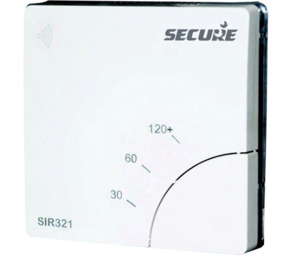
SIR 321 is a Z-Wave® countdown timer that can be used to control immersion heater elements or other electrical appliances rated up to 3 kW.
SIR 321 uses Z-Wave radio frequency technology to communicate with network controllers from Secure or other manufacturers. It is a mains-powered device that can also act as a network repeater.
INSTALLATION AND CONNECTION SHOULD ONLY BE CARRIED OUT BY A SUITABLY QUALIFIED PERSON AND IN ACCORDANCE WITH THE CURRENT EDITION OF THE IET WIRING REGULATIONS.
WARNING: ISOLATE MAINS SUPPLY BEFORE COMMENCING INSTALLATION AND ENSURE THE UNIT IS PROPERLY EARTHED.

The LEDs become operational when the unit is powered up.
User Instructions
To operate the unit press the BOOST button repeatedly until the indicator light for the required BOOST period is illuminated (see table below).
| Model | 1st-time button
press |
2nd-time button
press |
3rd time button
press |
4th-time button
press |
| SIR 321 | 30min (½ hour) | 60min (1 hour) | 120min (2-hour) | off |
When BOOST is active the indicator lights count down, showing the duration of the BOOST period remaining (see table below).
| Model | LED – 1 on | LED – 1 & 2 on | LED – 1, 2 & 3 on |
| SIR 321 | 5min to 30min left | 31min to 60min left | 61min to 120min left |
LED -1 will flash slowly when 5 minutes of the boost period remains and will flash at a faster rate when 1-minute remains. At the end of the boost period, SIR will automatically switch off the connected appliance.
SIR 321 can also run a timer from 1 minute to 24 hours, under Z-Wave® control. The RF LED shows the network and joining status (see STEP-5 for details).
The appliance can be switched off by canceling the boost period, using any of the following methods:
- If the BOOST button has just been pressed, wait for three seconds and then press it again. The indicator lights should all turn OFF.
- Press the BOOST button repeatedly, until ALL the indicator lights have turned OFF.
- Press and hold in the BOOST button until ALL the indicator lights have turned OFF.
Installation
A means of disconnection from the supply, having at least 3mm contact separation in both poles, must be incorporated in the fixed wiring. We recommend a separate fused circuit from the consumer unit (24-hour supply) protected by a 15A HRC fuse or, preferably a 16A MCB. In some cases immersion heater failure can damage the SIR. Installation of a 100mA RCD will provide additional protection for the unit. If the SIR is to be connected to a ring main then the spur feeding the controller should be protected in the same way. The SIR is NOT suitable for mounting on an unearthed metal surface.
THE SIR UNIT SHOULD BE KEPT IN ITS SEALED PACK UNTIL ALL DUST AND DEBRIS HAVE BEEN C L E A R E D A W AY P R I O R T O M A K I N G CONNECTIONS.
STEP-1 Unpack unit and remove front cover
Take the SIR out of its packaging and then remove the front cover gently, using a slotted screwdriver in the notch, as shown in the picture below:
STEP-2 Preparing SIR for surface wall mounting
SIR is suitable for mounting directly on to any surface mounted single-gang moulded box having a minimum depth of 25mm for UK, or 35mm for Continental Europe. Cable entry can be made through the most convenient cut-out.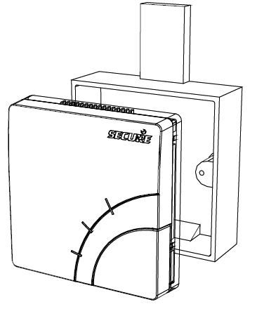
Remove cut-outs before fixing the box. Where appropriate, drill the box to provide close-fitting entry for cables and heat-resistant flexible cords. Take care to remove sharp edges.
Ensure that the clamp is positioned the right way up i.e. the projections on the underside of the clamp should grip the cord in order to secure the cable firmly. The cable clamp screws must be adequately tightened up to 0.4Nm.
For flush wall mounting
SIR can be mounted directly to any standard flush mounting single-gang wiring box with a depth of 25mm for UK (BS 4662), or 35mm for Continental Europe (DIN 49073). See pictures of gang boxes on page 23.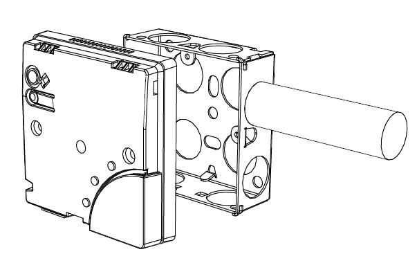
Clamp all surface wiring to the wall adjacent to the SIR, using trunking where appropriate. The flexible cable to the appliance should be passed through the cable entry hole in the bottom edge of the SIR, and secured under the cable clamp provided.
STEP-3 Making connections
Use twin-and-earth cable with a maximum conductor size of 2.5mm2 single conductor for the incoming supply to the SIR. Use a suitably rated three-core flexible cable to connect the SIR to the appliance to be switched. For appliances rated up to 2kW use minimum 1.0mm2 flexible conductors. For appliances rated up to 3kW use minimum 1.5mm2 flexible conductors. Heat resistant flexible cable must be used if connecting the SIR to an immersion heater.
| L in | Live in |
| N in | Neutral in |
| Supply earth terminal | |
| L out | Live out to appliance |
| N out | Neutral out to appliance |
| Appliance earth terminal |
All un-insulated earth conductors must be sleeved and connected to the earth terminals on the back of the SIR. The supply earth conductor and appliance earth conductor must use the separate terminal connections provided.
Switch off the mains supply and then connect the conductors for the incoming supply and the appliance on the back of the unit, as shown on the next page. Connect the two leads from the optional external temperature sensor probe (if supplied). The probe wires do not have any polarity.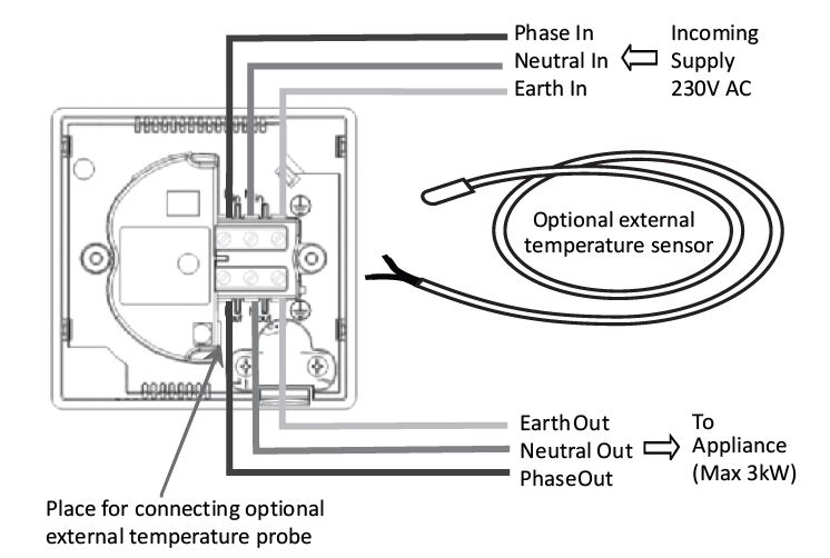
STEP-4 Installing SIR on wall gang / flush wall box
Carefully offer the SIR to the molded/metal box and secure using two screws. Take care not to damage the insulation or trap the conductors when fitting to the flush wall box.
STEP-5 Z-Wave® commissioning notes
To include the SIR onto a Z-Wave® network, first put the controller in inclusion mode (refer to controller installation instructions) and then press and hold the pairing button on the unit until the RF LED starts flashing at a fast rate. Then release the button.
On successful inclusion, the RF LED will stop flashing.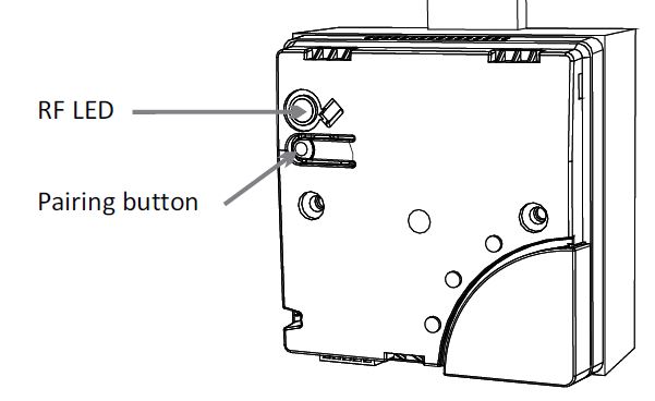
To exclude the SIR from a network, put the controller in exclusion mode (refer to controller instructions) and then follow the sequence for inclusion, as above. After successful exclusion the RF LED will flash slowly.
| Unit not signed on to network | RF LED slow flashing |
| RF inclusion/exclusion process | RF LED fast flashing |
| RF link lost to the controller | RF LED glow solid |
| RF network status is okay | RF LED off |
For optimum RF communication, fit the unit above floor level, and at least 30cm away from metal objects and appliances such as: microwave oven, cooker, fridge/freezer, stainless steel sink,TV, set-top box (satellite/cable/Freeview), radio or computer (desktop/laptop/tablet).
Do not fit the unit within 100cm of RF devices, such as DECT cordless phones or Wi-Fi routers.
It may be necessary to relocate the unit if problems with communication occur.
Mobile phones should not be used or placed in the vicinity of this unit.
STEP-6 Fitting front cover and final check
After fitting the mounting screws, fix the front cover back on. Offer the front cover on to the unit and make sure that it clicks securely in place.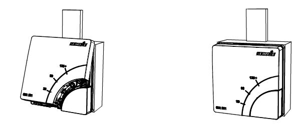
Finally switch on the mains supply and check that the SIR switches the appliance on and off correctly.
Z-Wave command classes support on SIR 321
| Z-Wave Device Classes | Implemented Device Classes |
| Generic | Binary Switch |
| Specific | Not used |
| Basic | Routing Slave |
| Command Classes Supported | Description |
| Manufacturer Specific
(V2) |
Secure Controls (UK) Manufacturer ID, RF
Module Serial Number |
| Version | Provides the version number of the software |
| Binary Switch | Binary Switch Set Binary Switch Get Binary Switch Report |
| Schedule | Schedule Supported Get Schedule Set Schedule Get Schedule Remove Schedule State Get Schedule ID: 0x01 Supported CC: Binary Switch SET command Type of Schedule: Start now |
| Basic | Mapped to binary switch command class as follows: Basic Set: Binary Switch Set Basic Get: Binary Switch Get Basic Report: Binary Switch Report |
| Association | Two association groups are supported : Group-1: Nodes to receive Schedule report Group-2: Nodes to receive multilevel sensor report Each group contains maximum 4 nodes. Note: Group-2 is available only when the external temp sensor is connected. |
| Multilevel sensor | Multilevel Sensor Get Multilevel Sensor Report |
Note: All command classes are version 1 unless otherwise stated.
Configuration
| Parameter name | Parameter No | Size in Bytes | Unit | Resolution | Min value | Max Value | Default value |
| Enable Fail safe
timer |
1 | 1 | – | – | 0 | 255 | 0 |
| Temperature Scale | 2 | 1 | °C
°F |
–
– |
0
128 |
127
255 |
0
0 |
| Temperature
reporting intervals |
3 | 2 | Sec | 1 | 1 | 65534 | 0 |
| Delta configuration temperature reporting | 4 | 2 | °C
°F |
0.1
0.1 |
1
1 |
100
500 |
0
0 |
| Temperature Cutoff | 5 | 2 | °C
°F |
0.1
0.1 |
1
320 |
1000
2120 |
0
0 |
| Note: – 1. Entering out-of-range values will be ignored 2. With ZERO default value, reporting & cut-off temperature is disabled. |
|||||||
Service and Repair
SIR is NOT user serviceable. Please do not dismantle the unit. In the unlikely event of a fault occurring please contact a heating engineer or a qualified electrician.
Technical specifications
Electrical
- Purpose of control Electronic timer (independently mounted)
- Contact rating 13(3)A, 230V AC, suitable for loads up to 3kW
- Control type Micro-disconnection
- Supply 230V AC, 50Hz only
- Control action Type 2B
Operation time
- limitation Intermittent
- Software class Class A
- Timing accuracy (±5%)
- Timer boost period Model SIR 321 – 30/60/120 minute, 1 minute to 24 hours via Z-Wave
- Sensor temp. accuracy ±0.5°C from 0°C to 65°C (optional external probe for SIR 321)
- Sensor temp. range 0°C to 100°C (optional external probe for SIR 321)
Mechanical
- Dimensions 85 x 85 x 19 mm (flush mount), 85 x 85 x 44 mm (surface mount)
- Case material Ball pressure test Thermoplastic, flame retardant
- Temperature 75°C
- Mounting Single-gang surface mount/flush box, minimum depth 25 mm (UK) / 35 mm (Continental Europe)
Environmental
- Impulse voltage rating Cat II 2500V
- Enclosure protection IP 30
- Pollution degree Degree 2
- Operating temperature range 0°C to 35°C
Compliance
Design standards EN 60730-2-7, RoHS, R&TTE
ETSI EN 300 220-2
ETSI EN 301 489-3
Ordering information
SIR 321 RF Z-Wave® variant, 30 to 120 minute countdown timer with single push-button operation and 1-minute to 24-hour timer over RF. LED indicator lights. Suitable for loads up to 3kW at 230V AC.
SIR 321 is suitable to install on illustrated types or any other similar type of wall gang/back boxes.
Optional accessory: SES 001, external temperature probe.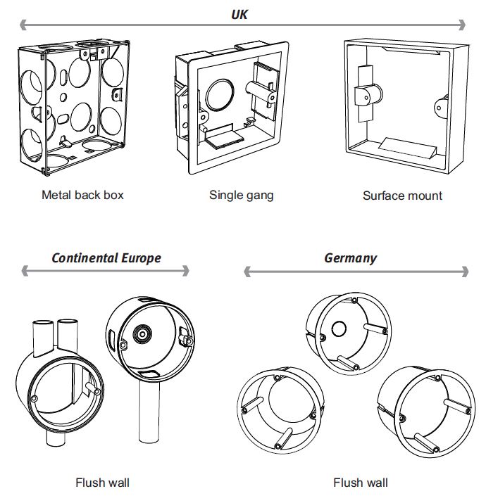
European Sales Office CEWE Instrument AB Box 1006, 611 31 Nyköping t: +46 8 600 80 60
e: [email protected]
www.securetogether.eu
European Head Office Secure Controls (UK) Ltd. Roman Farm Road Bristol, BS4 1UP
Reference
Download manual:
Secure SEC_SIR321 Z-Wave Thermostat Installational Manual
Other Manual:
Secure SEC SIR321 Z-Wave thermostat Quick Start Guide
Secure SEC_SIR321 Z-Wave thermostat Product Specification Guide
Leave a Reply