Savant SST-W100 Wireless Digital Thermostat

Feature Summary
- Wi-Fi enabled thermostat
- Supports standard or heat pump HVAC systems
- Includes 128 x 64 backlit graphical display
- Local temperature displays on backlit LCD
- Setpoint display and control
- System mode (off, auto, heat, and cool)
- Fan display and control (auto and on)
- Six buttons with on-screen labels
- Fahrenheit or Celsius modes
- Optional remote sensors
- Integrates easily with TrueControl™
- Automatically sends changes, so there is no polling.
Description

The Savant Wireless Thermostat (SST-W100) is a Wi-Fi-enabled wireless digital thermostat designed to control Heating, Ventilation and Air Conditioning (HVAC) systems.
The SST-W100 contains a robust thermostat interface and is designed to integrate seamlessly into a Savant-controlled environment. Using the TrueControl iPad® app for the HVAC Scheduler allows for instant changes and scheduling of climate setpoints throughout areas of a facility or home. The app also provides an instantaneous and historical view of the temperature, humidity, setpoints, and stage information.
HVAC System Compatibility
- Centralized HVAC systems or separate heating/ cooling systems can use separate Rh/Rc transformers
- Standard gas/electric HVAC system: two-stage heating, two-state cooling
- Heat pump HVAC systems: three-stage heating, two-state cooling
- Fan System: Selectable for gas or electric heat systems
- Heat pump changeover valve (reversible valve): selectable for changeover with heat or changeover with cool
- Emergency heat: in heat pump mode emergency heat is directly selectable from the thermostat
Thermostat Features and Operations of HVAC systems
The SST-W100 supports two types of HVAC systems, which are set up from the Mechanical Settings menu:
- Standard gas/electric system
- Heat pump system
The next table shows the staging information for a standard gas/electric system. The delta T setting is the delta, or difference between, the setpoint and current temperature for determining when a heat or cool call comes on. The “delta” is the number of degrees away from setpoint.
NOTE: The ON values shown for stage 1 or stage 2 Delta T are the default settings—for either Fahrenheit or Celsius modes. The default OFF Delta T for all stages is zero (0). The default settings can be changed from the Installer Settings menu.
Use this legend to identify the outputs shown in the next table:
- G: Fan output
- W1: Furnace stage 1 heating output
- W2/O: Used as the W2 furnace stage 2 heating output
- Y1: Compressor stage 1 cooling output
- Y2: Compressor stage 2 cooling output
|
Stage |
Stage Turns on at… (turns off setpoint) | Outputs |
Notes |
||||
| G | W1 | W2/O | Y1 | Y2 | |||
| Standard Gas Heat | |||||||
|
Heat 1 |
Stage 1 heat delta T
(1 degree) below setpoint |
W1 |
No fan output required for gas heating systems | ||||
|
Heat 2 |
Stage 2 heat delta T (3 degrees) below setpoint |
W1 |
W2 |
Second Stage Heat must be enabled
Minimum run time (MRT) between stages |
|||
|
Cool 1 |
Stage 1 cool delta T
(1 degree) above setpoint |
G |
Y1 |
||||
|
Cool 2 |
Stage 2 cool delta T (3 degrees) above setpoint |
G |
Y1 |
Y2 |
Second Stage Cool must be enabled
MRT between stages |
||
| Standard Electric Heat | |||||||
|
Heat 1 |
Stage 1 heat delta T
(1 degree) below setpoint |
G |
W1 |
||||
|
Heat 2 |
Stage 2 heat delta T (3 degrees) below setpoint |
G |
W1 |
W2 |
Second Stage Heat must be enabled
MRT between stages |
||
|
Cool 1 |
Stage 1 cool delta T
(1 degree) above setpoint |
G |
Y1 |
||||
|
Cool 2 |
Stage 2 cool delta T (3 degrees) above setpoint |
G |
Y1 |
Y2 |
Second Stage Cool must be enabled
MRT between stages |
||
The next table shows the staging information for a heat pump system. The delta T setting is the delta, or difference between, the setpoint and current temperature for determining when a heat or cool call comes on. The “delta” is the number of degrees away from setpoint.
NOTE: The ON values shown for stage 1 or stage 2 Delta T are the default settings—for either Fahrenheit or Celsius modes. The default OFF Delta T for all stages is zero (0). The default settings can be changed in the Installer Settings menu.
Use this legend to identify the outputs shown in the next table:
- G: Fan output
- W1: Auxiliary Heat (electrical heat strips) output
- W2/O: Used as the O changeover valve output
- Y1: Compressor stage 1 output (heat/cool depends on O terminal)
- Y2: Compressor stage 2 output (heat/cool depends on O terminal)
|
Stage |
Stage Turns on at… (turns off setpoint) | Outputs |
Notes |
||||
| G | W1 | W2/O | Y1 | Y2 | |||
| Heat Pump Changeover with Cooling | |||||||
| Heat 1 | Stage 1 heat delta T
(1 degree) below setpoint |
G | Y1 | ||||
|
Heat 2 |
Stage 2 heat delta T (3 degrees) below setpoint |
G |
Y1 |
Y2 |
Second Stage Heat must be enabled
Minimum run time (MRT) between stages |
||
|
Heat 3 |
Stage 3 heat delta T (5 degrees) below setpoint |
G |
W1 |
Y1 |
Y2 |
Auxiliary Heat must be enabled
MRT between stages W1 is used for the auxiliary heat (heat strips) output |
|
| Cool 1 | Stage 1 cool delta T
(1 degree) above setpoint |
G | O | Y1 | W2/O terminal is used for the “O” changeover output | ||
|
Cool 2 |
Stage 2 cool delta T
(3 degrees) above setpoint |
G |
O |
Y1 |
Y2 |
Second Stage Cool must be enabled
MRT between stages |
|
| Heat Pump Changeover with Heating | |||||||
|
Heat 1 |
Stage 1 heat delta T
(1 degree) below setpoint |
G |
O |
Y1 |
W2/O terminal is used for the “O” changeover output | ||
|
Heat 2 |
Stage 2 heat delta T (3 degrees) below setpoint |
G |
O |
Y1 |
Y2 |
Second Stage Heat must be enabled
MRT between stages |
|
|
Heat 3 |
Stage 3 heat delta T (5 degrees) below setpoint |
G |
W1 |
O |
Y1 |
Y2 |
Auxiliary Heat must be enabled
MRT between stages W1 is used for the auxiliary heat (heat strips) output |
|
Cool 1 |
Stage 1 cool delta T
(1 degree) above setpoint |
G |
Y1 |
||||
|
Cool 2 |
Stage 2 cool delta T (3 degrees) above setpoint |
G |
Y1 |
Y2 |
Second Stage Cool must be enabled
MRT between stages |
||
Multistage Heating Control

- When configured with a multistage heating system, the next figure shows the expected temperature control behavior of the thermostat (SST-W100).
| System Variables | Setting |
| System Type | Heat Pump |
| Heat Stage 1 On | 1 |
| Heat stage 1 Off | 0 |
| Heat Stage 2 On | 2 |
| Heat Stage 2 Off | 0 |
| Aux Heat On | 3 |
| Aux Heat Off | 0 |
| Heat Stage 2 Enabled | Y |
| Aux Heat Enabled | Y |
- MRT: Minimum Run Time. Once a call for a heating stage starts, it is forced to run for the MRT time (Default 3 minutes). That stage will run for the MRT period regardless of the room temperature or setpoint delta. Subsequent stages are inhibited until the current stage MRT expires. After the MRT period, the stage will run until it reaches it’s offsetting. (default set to the point)
- MOT: Minimum Off Time. At the end of a stage call, it triggers an MOT timer and is prevented from starting again until the MOT expires. (Default 5 minutes)
- Delta T: Delta T is the number of degrees from the setpoint that a stage turns on or off. Each stage has an ON delta T and an OFF delta T. The Delta T settings are set in the Installer Settings menu.
Multistage Heating Control Graph
System Type
- As described previously two types of systems are supported: standard gas/electric or heat pump systems.
Fan Type
Note that the Fan Type is not valid for a heat pump system type. Two fan types are supported:
- Gas—the fan will not turn on with heat calls
- Electric—the fan will turn on for both heat and cool calls.
Changeover Type
This option is only valid for heat pumps. Two changeover types are supported:
- CO w/cool means the O will be energized for cool stages
- CO w/heat means the O will be energized for heat stages.
Celsius/Fahrenheit
- The thermostat can run in either Celsius or Fahrenheit mode. Fahrenheit is the default.
H/C setpoint delta
- This is the minimum delta between the heat and cool setpoints, this value can range between 3 and 15 degrees, with the default being 4 degrees.
Minimum Off Time
- This is the minimum amount of time that a stage must remain off, once it is turned off, the range is between 5 and 9 minutes with the default being 5 minutes.
Minimum Run Time
- This is the minimum amount of time that a stage must remain on, once it is turned on, the range is between 1 and 9 minutes with the default being 3 minutes.
Delta On/Off Settings
As shown in the previous graph, each stage (H1, H2, H3, C1, C2) has a delta in degrees for turn-on value, and turnoff value. The default settings are shown in the next table.
| Parameter | Range
(degrees) |
Default Value
(degrees) |
| H Delta Stage 1 On | 1 – 8 | 1 |
| H Delta Stage 1 Off | 0-8 | 0 |
| H Delta Stage 2 On | 1 – 8 | 3 |
| H Delta Stage 2 Off | 0-8 | 0 |
| H Delta Stage 3 On | 1 – 8 | 5 |
| H Delta Stage 3 Off | 0-8 | 3 |
| C Delta Stage 1 On | 1 – 8 | 1 |
| C Delta Stage 1 Off | 0-8 | 0 |
| C Delta Stage 2 On | 1 – 8 | 3 |
| C Delta Stage 2 Off | 0-8 | 0 |
Stage Enables
- Heat Stage 2, Auxiliary Heat and Cool Stage 2 all have independent enable and disable functionality.
Fan Cycler
The fan cycler will cycle the fan on and off based on the fan uptime and fan downtime settings. The uptime has a range of 0-120 minutes with a default of zero (off). The downtime has a range of 10-120 minutes with a default of 10 minutes. The heat and cool cycles call for the fan to be on will take precedence over the cycler trying to turn it off.
Fan Purge
- The fan purge will keep the fan on past the cool call for a configurable period, the range is set from 0-120 seconds, with zero being the default.
Minimum Cool Setpoint
- This is the minimum cool setpoint. The range is 43 degrees to 112 degrees, with a default value of 60 degrees.
Maximum Heat Setpoint
- This is the maximum heat setpoint. The range is 40 degrees to 109 degrees, with a default value of 90 degrees.
Emergency Heat
An additional system mode, EHEAT for emergency heat will be displayed if the HVAC system type is set to heat pump. If there is a compressor failure with the heat pump system, setting the mode to EHEAT will allow the supplemental auxiliary heat to come on first, whenever there is a call for heating. It also disables the compressor output to prevent further damage to the HVAC system.
HVAC Mode
The thermostat through the user interface, can easily be changed to run in one of four modes:
- Off: Heat or cool cycles will not be enabled
- Cool: Only cool cycles will be enabled
- Heat: Only heat cycles will be enabled
- Auto: Both heat and cool cycles will be enabled
Fan Mode
The fan through the user interface, can easily be changed to run in one of two modes:
- On: Fan is always on
- Auto: Fan is turned on/off by the heat and cool calls or by the cycler
On Board Temperature Sensor
The SST-W100 has a local temperature sensor that is, by default, the sensor used for all the algorithms. This sensor can be calibrated to +/- 7 degrees. For more details, see the Remote Sensor Features section to understand how to use remote sensors.
Humidity Features
The SST-W100 provides the capability to monitor, display and control the humidity in a room. The control is either implemented by extending the cool cycles or by the control of built-in auxiliary relays. These relays can be configured to control a humidifier, dehumidifier, vent or DH Fan control.
Humidity Control Logic
The Humidity Control Logic (HCL) will extend a cool call if the following conditions are met. The HCL logic will not initiate a cool call—the HCL will terminate its cool call upon any of these conditions not being met as well.
- RH Mode is enabled
- HVAC Mode is Cool or Auto
- HVAC System is in an active cool call
- RH is greater then or equal to the RH setpoint plus the RH Delta
- The temperature is above the cool setpoint minus the RH temperature setpoint
- The RH on timer has not expired
- The RH off timer is not running
Auxiliary Relays
Two auxiliary relays, A1 and A2, can be configured with the various options described in the next table.
| Option | Description |
| Off | Relay has no function |
|
Humidifier |
Relay is assigned as an external humidifier control output. The Relay is active when it is enabled in this mode and the system mode is set to Heat or Auto, if the last call was for heat. It will be ON when the room humidity is 2º below the RH setpoint. The system fan (blower) can also be configured to turn on with relay A1 when the A1 Relay Blower Interlock is enabled. |
|
Dehumidifier |
Relay is assigned as an external dehumidifier control output. The Relay is active when it is enabled in this mode and the system mode is set to Cool or Auto if the last call was for cool. It will be ON when the room humidity is 2º above the RH setpoint. The system fan (blower) can also be configured to turn on with relay A1 when the A1 Relay Blower Interlock is enabled. |
|
Network |
Relay is assigned as a Savant System-controlled output. Relay is on/off state and is set according to triggers and workflows. The system fan can also be configured to turn on with relay A1 when the A1 Relay Fan Interlock is enabled. |
| Vent | Relay control. Relay is assigned as an external vent damper control output. The relay is ON when the Fan Cycler state is ON. |
|
DH Fan Control |
(Only A1 supports this mode) Relay is assigned as an external dehumidification fan speed control output (DH). For use with air handlers having an external DH fan control input to slow fan speed during dehumidification. Relay is OFF during normal operation when RH level is below the RH setpoint. Relay is ON when RH level is above the RH setpoint.
NOTE: Set jumper JP2 on the A1 relay to the NC position. |
Humidity User Settings
The following user settings can be configured.
| Option | Description |
| Humidity Setpoint | Used by both the HCL and the auxiliary relays when in a humidifier or dehumidifier mode. Range is 20%-80% in 55 increments. Default is 55%. |
| Humidity Mode | Enables or disables the HCL logic. |
| Humidifier Mode | Enables or disables the Humidifier logic.
This is only exposed, if either A1 or A2 is set to Humidifier. |
| Dehumidifier Mode | Enables or disables the Dehumidifier logic.
This is only exposed if either A1 or A2 is set to Dehumidifier. |
Humidity Installer Settings
The following installer settings can be configured.
| Option | Description |
| RH Sensor Calibration | +/1-7% in 1% increments. Default is 0% |
| RH Temperature Delta | Used in the HCL algorithm. Range is 1-5 degrees. Default is 2 degrees. |
| RH Setpoint Delta | Used in the HCL algorithm. Range is 1%-10%. Default is 5%. |
| Humidity On Time | Used in the HCL algorithm. Range is 0-60 minutes. Default is 30 minutes. |
| Humidity Off Time | Used in the HCL algorithm. Range is 0-60 minutes. Default is 30 minutes. |
| Humidity Off Delta | Used in the HCL algorithm, it has a range of 0-10% Default is 2%. |
| A1 Relay Mode | See the section, Auxiliary Relays. Default mode is off. |
| A2 Relay Mode | See the section, Auxiliary Relays. Default mode is off. |
| A1 Fan Interlock | This locks the state of the fan to the state of the relay when the A1 relay is in humidifier, dehumidifier, or network mode. Default is off. |
| A2 Fan Interlock | This locks the state of the fan to the state of the relay when the A2 relay is in humidifier, dehumidifier, or network mode. Default is off. |
Humidity Hardware
- Humidity Sensor -: +/- 4.5%.
- Humidity Relay A1: – 1A, 24VAC
- Humidity Relay A2: – 1A, 24VAC
Remote Sensor Features

The thermostat has two remote sensor connections, RS1 and RS2. When connected RS1 will replace the internal temperature sensor. RS2 can either be an averaging sensor (indoors), or an outdoor temperature sensor depending on the remote sensor setup in the thermostat’s Installer Settings menu.
The remote sensor function depends on what sensors are connected, as outlined in the next table.
| Sensors | Internal | RS1 | RS2- IN
Averaging |
RS2-OUT
Outdoor |
Sensor Function |
| Internal only | Yes | No | No | Use internal sensor for room temperature | |
| RS1 only | Not used | Yes | No | Use RS1 sensor for room temperature Internal sensor not used | |
| RS2 only as IN | Yes | No | Yes | Average internal sensor with RS2 sensor and use the average for room temperature | |
| RS1 and RS2 as IN | Not used | Yes | Yes | Average RS1 and RS2 sensors and use the average for room temperature | |
| RS2 only as OUT | Yes | No | Yes | Internal sensor used for room temperature RS2 sensor used for outside temperature | |
| RS1 and RS2 OUT | Not used | Yes | Yes | RS1 sensor used for room temperature RS2 sensor used for outside temperature |
Sensor Calibration
- Each sensor can be calibrated to +/- 7 degrees.
Display Features

The SST-W100 includes a 128×64 backlit graphical display. Using this display screen the user can monitor the temperature, humidity and the state of the HVAC system. From the screen, the user can also change modes and setpoints. By pressing and holding the Hold button, the installer can modify any of the parameters used in the algorithms supported. There is also a list of features that belong to the display itself, that are described below the figure.
Display Lock
- The display can be locked, so that the user can not change anything.
RH Display Enable
- The ability to display the Relative Humidity can be enabled or disabled. The default is disabled.
Outside Temperature
- If Remote Sensor 2 (RS2) is set for outside temperature or the outside temperature is set via the Savant system, the temperature can be displayed on the main menu.
Contrast
- The contrast of the screen can be adjusted in a range from 0 to 20, with a default value of 14.
Backlighting
- When the display is ON, can be adjusted from 0 to 100% in 5% increments with a default value of 100%.
- When the display is OFF, can be adjusted from 0 to 100% in 5% increments with a default value of 0%.
- The amount of time the thermostat will reside with the backlight on, before timing out to the backlight off, the range is from 20-120 secondsThe default value is 20. The value zero will keep the backlight on for ever.
Screen Timeout
The amount of time the thermostat will reside on a screen that the user has chosen, before timing out to the main screen, is set within the range: zero (0), or 20-120 seconds. Zero is the default. The value zero will display the screen indefinitely.
Integration Features
- The Savant Wireless Thermostat is integrated with Savant’s TrueControl™ app and therefore can be programmed from an Apple® iOS device.
Wi-Fi Support
The SST-W100 includes an FCC/CE/IC certified 2.4 GHz IEEE 802.11b/g transceiver. This is used to communicate with the Savant control system. The thermostat supports DHCP or Static IP addresses, and it supports WPA1, WPA2 or WEP Security. If the network router supplies WPS, then the SST-W100 can automatically find and join the secure Wi-Fi network. The SST-W100 is sending changes as they happen, so the Savant control system does not have to poll the thermostat—as it does with many other thermostats that are available. This reduces the network traffic and improves synchronicity between all user interfaces. A change on the thermostat will instantly appear on the TrueControl user interface.
HVAC Control
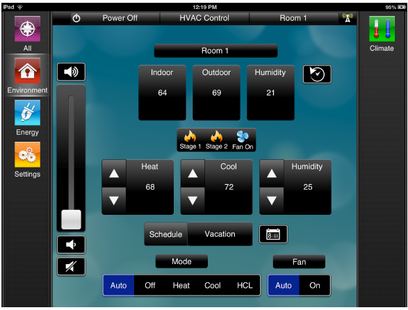
The HVAC user interface provides instantaneous access to control a zone, as well as, displays what is happening in that zone. By default, the app will present the ability to change the heat, cool and humidity setpoints—as well as display the temperature, outdoor temperature, and humidity values. The interface also shows what schedule is running and allows the user to change the modes, if desired. The user will also see indications of whether the various heating and cooling stages are running or not.
HVAC Scheduling through the TrueControl application

The HVAC Schedule allows the end user to establish and control their HVAC system using an interactive scheduling system. Using the HVAC Schedule on your iPad®, you can enter heating, cooling, humidifying and dehumidifying times for the day, week, season, and vacation.
HVAC History

- The figure above shows the current temperature, heat point, cool point, Heat 1-3, Cool 1-2, and fan.
The HVAC user interface for the SST-W100 enables a process on the control system, by default, which tracks the history of the temperature, outside temperature, humidity, and all the setpoints—as well as, all the stage information of what is on or off. This history can be seen in various time increments for up to a year’s worth of data. The enabled process will also read the outdoor temperature from a state and copy it to all the SST-W100s so that they can all display the outdoor temperature.

- The figure above shows the current humidity, humidity setpoint, Cool 1-2, fan, and auxiliary relays (A1, A2)
Rear View of SST-W100
With the SST-W100 the wiring can be set up for either a standard Gas/Electric HVAC system or heat pump HVAC system.

Wiring Legend

Screw-down connectors on the inside of the back cover of the SST-W100 are used for wiring connections to various climate control devices. Use the next figure to identify these connectors described in the next table.
| Left Side | Right Side | ||
| 24RC | Cooling 24V | 24C | 24V AC Common (Required) |
| G | Fan Output | 24RH | 24V Heating |
|
Y1 |
Cooling (Compressor) Stage 1 output |
W1 |
Heat Stage 1 output (standard gas/electric HVAC)
Auxiliary Heating (heat pump HVAC) |
|
Y2 |
Cooling (Compressor) Stage 2 output |
W2/O |
Heat Stage 2 output (standard gas/electric HVAC)
Changeover Valve (heat pump HVAC) |
| RS2 | Remote Sensor 2 | RS1 | Remote Sensor 1 |
| RS2 | Remote Sensor 2 | RS1 | Remote Sensor 1 |
| RSC | Sensor Shield | RSC | Sensor shield |
| A1 | Auxiliary 1 Relay | A2 | Auxiliary 2 Relay |
Specifications
| Dimensions and Weight | |
| Height | 3.96 in/10.06 cm |
| Width | 5.775 in/14.67 cm |
| Depth | .58 in/1.47 cm |
| Weight | .5 lb/.23 kg |
| Power | |
| Power Supply | 24V AC (requires both R and C from the HVAC system) |
| Maximum Power Draw | 200mA |
| Compliance | |
| Safety and Emissions | FCC Part 15
UL Class 2 |
| RoHS | Compliant |
| Wiring Requirements | |
| 18 American Wire Gauge (AWG)
Uses standard thermostat connections (C, R, W1, W2, Y1, Y2, G) Flush Mount NOTE: Requires both R and C wires from an HVAC system. |
|
| Remote Temperature Sensor (optional) | |
| The SST-TEMP1 sensors provide precision room temperature sensing for climate control systems. The sensors include high precision thermistor or Resistance Temperature Detector (RTD), accurate to 0.2C (+/- .36F) over range of 0C to 70C. The platinum RTD is accurate to 0.4C.
Cat 3/5/6 cable (24 GA)—maximum length 100 feet for single pair, or 200 feet with double pair wiring. For more details on installing an SST-TEMP1, see the SST-TEMP1 Quick Reference Guide. |
|
| Enclosure | |
| White | |


Included Items
The items included in the installation kit for the SST-W100 are outlined in the next table.
Description /Quantity
- Phillips head screws for wall mounting: 2
- Quick Reference Guide: 1
Required Components
The system components required for use with the SST-W100 are outlined in the next table.
Description /Model Number
- Ethernet Network: Enterprise-grade network deployment supporting IEEE 802.11b/g
Accessories
The accessories available for use with the SST-W100 are outlined in the next table.
Description /Model Number
- Temperature Sensor: SST-TEMP1
Dimensions

- The next figures show the top and front dimensions of the SST-W100.
Contact
- 45 Perseverance Way, Hyannis, MA 02601
- P: 508-683-2500
- F: 508-683-2600
- www.SavantSystems.com
052913 009-0729-02
Copyright © 2012 Savant Systems, LLC. SAVANT and RacePoint Blueprint are trademarks of Savant Systems, LLC.
All brand names, product names and trademarks are the property of their respective owners.
Savant Systems, LLC reserves the right to change product specifications without notice.
Reference
Download Manual:
Savant SST-W100 Wireless Digital Thermostat Product Specification Guide
Savant SST-W100 Wireless Digital Thermostat Product Specification Guide