
Savant CLI-W210 Smart Programming Thermostat
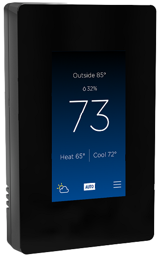
- Document Number: 009-1973-01
- Document Date: October 2020
- Document Supports: CLI-W210 and CLI-W200
- Web UI version 0.1.0 and higher
This guide contains information on advanced programming for CLI-W200 and CLI-W210 Savant Multistat Smart Thermostat devices via their embedded web portal interface. Topics covered include the following:
- Connecting to the thermostat’s web user interface.
- Descriptions of the fields within the web UI and their functions.
- Procedures for building configuration files and deploying to thermostats.
- Configuration file examples.
Important Safety Information
Read First
Before installing, configuring, or operating any equipment and other, Savant recommends that each dealer, integrator, or installer, access and read all the relevant technical documentation. Savant technical documentation can be located by visiting the Savant Community. Vendor documentation is supplied with the equipment. Read and understand all safety instructions, cautions, and warnings in this document and the labels on the equipment.
Safety Classifications In this Document
- NOTE: Provides specific information for installing, configuring, and operating the equipment.
- IMPORTANT: Provides specific information that is critical to installing, configuring, and operating the equipment.
- CAUTION: Provides specific information for avoiding situations that may cause damage to equipment.
- WARNING: Provides specific information for avoiding situations that may cause physical danger to the installer, end-user, etc.
Electric Shock Prevention
- ELECTRIC SHOCK: The source power poses an electric shock hazard that has the potential to cause serious injury to installers and end users.
- ELECTRICAL DISCONNECT: The source power outlet and power supply input power sockets should be easily accessible to disconnect power in the event of an electrical hazard or malfunction.
Weight Injury Prevention
- WEIGHT INJURY: Installing some of the Savant equipment requires two people to ensure safe handling during installation. Failure to use two installers may result in injury.
Safety Statements
All safety instructions below should be read, understood, and applied under all relevant circumstances when working with this equipment.
- Follow all input power ratings marked on the product near power input!
- If fuse replacement is required, the replacement fuse should match fuse rating marked on the product.
- Do not use equipment near water.
- Clean only with a dry cloth.
- Do not block any ventilation openings or install near any heat sources such as heat registers, stoves, radiators, amplifiers, etc.
- Refer all servicing to qualified service personnel. Servicing is required when any part of the apparatus has been damaged in any way, or fails to operate normally for any reason.
- Use only attachments/accessories specified by the manufacturer, following all relevant safety precautions for any such attachments/ accessories.
- For applicable equipment, use the included power cord with the grounding prong intact to insure proper grounding of the device.
- If the provided plug does not fit the desired outlet, contact a licensed electrician to replace the obsolete outlet.
- Protect any power cord from being walked on, pinched, strained, or otherwise potentially damaged, especially at the outlet or device connections.
- Disconnect any outlet-powered apparatus from its power source during lightning storms or when unused for long periods of time.
- To completely disconnect equipment from AC mains power, disconnect the power supply cord plug from the AC receptacle on the device.
- For any hardwired or fixed in-wall apparatus, carefully follow all wiring diagrams and instructions. All electrical wiring and servicing should be performed by a properly licensed electrician.
Before You Begin
Helpful Information
- All thermostats must be provisioned to the local network and assigned an IP address before connecting to the web portal can be established.
- The on-screen menus on the thermostat set the following:
- User interface functions for the thermostat.
- Any basic essential HVAC functions needed to manage an HVAC system.
- The web portal UI described in this document can be used to configure all settings covered by the thermostat’s on-screen menu, with additional capability to:
- Use the web portal’s advanced functions to customize an existing configuration or template file.
- Add more than one HVAC system on-screen menus can add only one). Note: Additional systems are managed via the Pro App.
- The CLI-W200/W210 thermostat contains the relays needed to control one HVAC system (W1, W2, Y1, Y2, G, O). To manage more than one system, a CLI-PTACKK1 climate module can be added. There are, however, a few scenarios where the thermostat can manage more than one HVAC system. An example would be to use the traditional relays (W1, W2, Y1, Y2, G, O) to control a heat pump type system and use the Aux Relay (Aux) to switch a second radiant type system.
- The table below indicates which interface can be used to set the various functions in an HVAC system.

- In the web portal, the blue-colored text indicates the text is a link. Selecting the blue text will direct the user to that function in the web portal. Selecting the link directs the user to the relevant screen.
- Select the Deploy Button to send the changes made in the web portal to the thermostat. Changes made in the web portal are not automatically sent to the thermostat.
All related documentation is available on the Savant Community
- Multistate Smart Thermostat Quick Start Guide: This guide provides information on the various technical specifications, regulatory information, feature descriptions, essential power connections, and remote sensor wiring. This guide also contains information needed to install the thermostat and add it to the local network. When complete, the thermostat will be ready to add to a Savant Pro system.
- Pro App HVAC Service User Guide: Once the thermostat is operating in a Savant Pro system, this guide contains the information needed to navigate the HVAC Service in the Savant Pro App.
- Multistate Smart Thermostat Deployment Guide: This guide describes how to add the thermostat to a Savant control system, which includes HVAC signal wiring diagrams, provisioning instructions, Blueprint integration, and HVAC data table information.
Connecting To the Web Portal
Before connecting to the web portal, the thermostat must be provisioned to the local network with an IP address assigned. The local IP is used to log in to the web UI via a browser, and can be found in the thermostat’s on-screen menu (see below).
- Power-on the thermostat and allow to boot.
- From the Select Network To Connect screen, select a network.
- Enter the password to the network and select DONE. A connected icon will appear for a few seconds once the thermostat is communicating with the Wi-Fi network and IP address is assigned.
- On the Configure HVAC System screen that opens, a choice is offered:
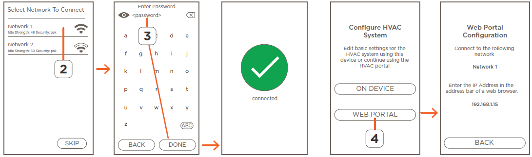
- ON DEVICE: Select the ON DEVICE option to configure the thermostat using the on-screen menu. This option is best used when deploying a simple HVAC configuration with no advanced programming required.
- WEB PORTAL: Select the WEB PORTAL button to open the Web Portal Configuration screen and locate the thermostat’s IP address. With the IP address known, any device with a web browser can be used to access the online web portal for that thermostat.
- Open a web browser and enter the IP address assigned to the thermostat.
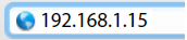 HELPFUL: Enter the IP address shown in the Web Portal Configuration screen. The IP address shown in the image to the right is just an example.
- First time users; read the Security Risk alerts output by the browser and select the appropriate buttons to continue. The alert offered by each browser type differs (Safari, Firefox, Chrome). Read the security warnings that open and, if agreed, select to accept the risks and continue.
- In the Racepoint System Monitor screen that opens, enter a password, and select the CREATE button to create a password. The password is accepted when the SUCCESS screen opens.
- Enter the password created in step 7 and select LOGIN to log on to the thermostat’s web portal.
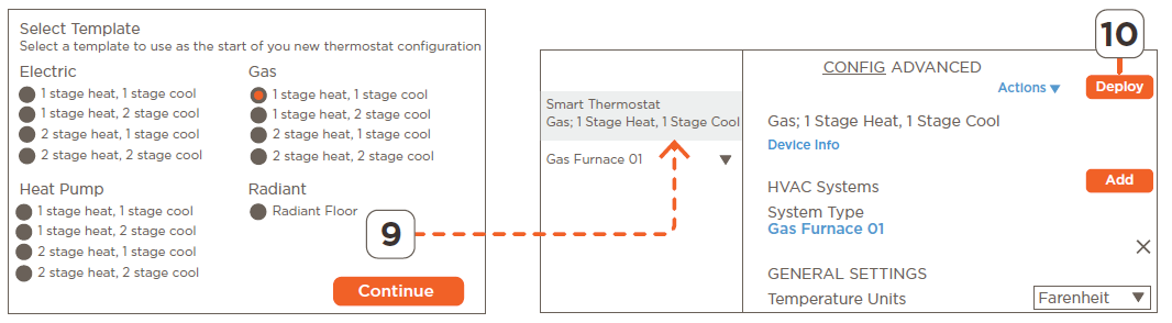
- Choose the template that most closely matches the HVAC system being controlled by the thermostat, then select Continue to proceed.
- Select the Deploy button to upload the template to the thermostat. The thermostat will reboot, and the configuration uploaded will now be available on the thermostat. As changes to the template are made from within the Web Portal, those changes can be uploaded at any time by selecting the Deploy button.
Connected to Local Network (IP Address Assigned )
To access the Web Portal to make changes to a configuration that is already loaded and running on a thermostat, follow the steps below.
- Select the HVAC mode icon from the thermostat’s main screen.
- Swipe left to access the ABOUT screen. Make a note of the IP address assigned to the thermostat.
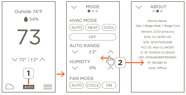
- Open a web browser and enter the IP Address.
- HELPFUL: Enter the IP address shown in the Web Portal Configuration screen. The IP address shown in the image to the right is just an example.
- First time users; read the Security Risk alerts output by the browser and then select the appropriate buttons to continue. The alert offered by each browser type differs (Safari, Firefox, Chrome). Read the security warnings that open and, if agreed, select to accept the risks and continue.
- In the Racepoint System Monitor screen that opens, enter a password, and select the CREATE button to create a password. The password is accepted when the SUCCESS screen opens.
- Enter the password created in step 5 and select LOGIN to log on to the thermostat’s web portal.
- As changes are made to the template from within the Web Portal, those changes can be uploaded at any time by selecting the Deploy button.
Web Portal Field Descriptions
- The layout and field descriptions of the web portal are described below.
User Interface Field Descriptions
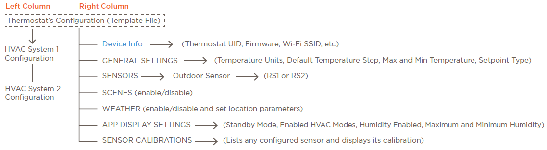
- Use the diagram below to help navigate through the user interface fields in the web portal.
GENERAL SETTINGS
- Temperature Units: Select either Fahrenheit or Celsius from the drop-down menu and all fields on the thermostat switch to the units selected.
- Default Temperature Step: Select the +/- buttons to raise or lower the step value of the heat and cool setpoints.
- Minimum or Maximum Temperature: Sets the maximum or minimum value that the heat and cooling setpoint can be raised or lowered on the user interface. To modify, select the +/- buttons to raise or lower the setpoints.
- Dual Setpoint: Enables and disables the dual setpoint user interface. Slide the button to the right to enable the dual setpoint user interface. Slide button to the left to enable the single setpoint user interface.
SENSORS
OUTDOOR SENSORS: When using an outdoor sensor, it must be assigned to either RS1 or RS2. Select the port that matches the designator on the thermostat’s backing plate where the sensor is wired.
- Select the Assign button linked to the Outdoor Sensor field.
- Select the rescan button to search for and discover all sensors in the system.
- Select the appropriate port from the Assign Sensor dialog that opens. Any ports from a climate module that accept a 10KΩ type sensor are listed as UID-<port #>.
- Select Save to add the sensor to the configuration.
HUMIDITY and TEMPERATURE CALIBRATION: When a sensor is not displaying the correct temperature or humidity, an offset can be applied to make the parameter displayed on the thermostat’s user interface more accurate. To apply an offset, follow the steps below.
- Compare the temperature data from the sensor added in the previous section to a known good thermometer. The difference in temperature is the offset.
- From the Temperature Calibration field, select the + or – button to add or subtract from the temperature displayed in the thermostat. With the offset added, the known good thermometer and temperature displayed should match (new offset must be deployed to the thermostat before it will appear).
- Apply the same calibration method to humidity when applicable. The Humidity Calibration field in this section adds or subtracts the offset to the data taken from the embedded humidity sensor located on the thermostat’s electronic board.
HELPFUL INFORMATION
- Indoor sensors should be assigned to a zone (HVAC System > Zones > Home).
- 1-wire smart sensors can’t be configured as outdoor sensors.
- When the weather forecast feature is enabled:
- The temperature data collected from an outdoor sensor overrides the temperature sent from the online weather app.
- When no outdoor sensor is configured, the temperature sent from the online weather app gets displayed as the outdoor temperature.
- In systems set with a heat pump and auxiliary heat, Savant recommends adding an outdoor sensor to the configuration. The data from the outdoor sensor gets compared to the temperature set in the balance point field. When the outside temperature goes below the value specified in this field, auxiliary heat is triggered.
IMPORTANT: Auxiliary heat can’t be triggered by the balance point when the weather data is taken from the online weather app. The data must be taken from a sensor configured as an outdoor type sensor.
SCENES
- Any Scene configured as a global/shared Scene that is available in the Savant Pro system will also be available to the thermostat. Slide the Enabled button to the right to enable the Scenes created for a Savant Pro system to display on the thermostat. When disabled, the Scenes won’t populate.
- This feature can be enabled from both the thermostat and the web portal.
HELPFUL: When there are multiple Hosts with associated Scenes connected to the same network, users must select one Host for the thermostat to take Scenes from. This can be completed via the thermostat’s on-screen display following the steps below:
- From the thermostat’s main screen, select the mode icon.
- Swipe left until the NETWORK screen is displayed.
- Select the CONFIGURATION button. Scroll down and select the HOST SETTINGS field.
- Verify the SAVANT SCENES field is set to ON.
- Select the primary Host that contains the users scenes.
- Select the BACK button.
- Select the FINISH button from the summary screen. The thermostat will reboot, and the scenes from the selected Host will be available in the thermostat’s user interface.
WEATHER
The weather forecast for the coming week can be made available on the thermostat. This process is described below and is completed in the Web Portal.
- Highlight the Smart Thermostat configuration file field from the left column.
- Scroll down to the WEATHER section and slide the Enabled icon to the right.
- Enter one of the following:
- City and state or zip code of the home. If latitude and longitude coordinates are known, they can be entered instead.
- Enable the location services on the MacBook and select the Locate button from the WEATHER section in the web portal. Selecting the Locate button will populate the Latitude and Longitude coordinates of your location to the web portal.
- Select the Deploy button from the top of the Configuration screen to send this information to the thermostat. The thermostat will reboot, and the weather forecast icon from the main screen on the thermostat will be active. Select this icon to open the weather forecast screen.
HELPFUL INFORMATION
- It may take a few minutes for the forecast to become active on the thermostat. Network speed and reliability can delay the forecast from becoming active.
- The temperature data from an outdoor sensor will override the temperature displayed in the weather forecast screen.
- The temperature sent from the online weather app is displayed to the weather forecast screen when there is no outdoor sensor configured.
APP DISPLAY SETTINGS
Standby Mode: The three back-lighting modes available are as follows:
- Normal: When set to normal, the touchscreen remains off by default. To activate or wake up the screen, either touch the LCD screen or initiate movement in front of the proximity sensor. As long as a user continues to work with the screen, it will remain active. After 30 seconds of no user activity, the display reverts to blank. NOTE: The proximity sensor is supported on the CLI-W210 only. To wake up the CLI-W200 model, the screen of the thermostat must be touched.
- Always On: The touchscreen is always on. The level of light in the room determines the brightness of the display.
- When the lighting level in the room is high, the brightness of the touch screen is bright.
- As the light level in the room dims, the brightness of the touchscreen also dims.
- Example: Before going to bed, the lights in the room are on, and the touchscreen’s level of brightness is high. Once in bed and the room is dark, the touchscreen brightness reduces until it is very dim so the person can sleep.
- Night Mode (available through the web portal only): Night Mode is similar to the Always On setting described above. The difference is when the room becomes very dark, the display will turn off.
Enabled HVAC Modes: Select from the drop-down menu, which HVAC modes will be available on the thermostat.
Humidity Enabled: Slide the button to the right to:
- Display the humidity on the thermostat’s main screen. The background of the slider in the web portal switches to orange once enabled.
- Enable control of auxiliary humidity equipment. See the Assign an Aux Relay to Control a Humidifier or Dehumidifier section.
Maximum/Minimum Humidity: Sets the maximum or minimum value that the humidity setpoint can be raised or lowered on the user interface. To modify, select the +/- buttons to raise or lower the setpoints.
SENSOR CALIBRATIONS
The accuracy of the data received from any temperature or humidity sensor may need an offset added or subtracted to the make what is displayed on the thermostat more accurate. This field lists an inventory of all sensors available in the configuration and offers a way to fix any inaccuracies.
local-internal: (CLI-W210 – The temperature sensor embedded on the thermostat’s electronic board). (CLI-W200 – The temperature sensor mounted inside the thermostat and connected to the RS1 terminals.
- Address: The software running on the thermostat uses this Address to identify the sensor. No changes to this field are needed.
- Humidity Calibration: Add or subtract an offset to the data received from the humidity sensor embedded in the thermostat.
- Temperature Calibration: (CLI-W210 – Add or subtract an offset to the data received from the temperature sensor embedded in the thermostat). (CLI-W200 – Add or subtract an offset to the data received from the sensor connected to the RS1 terminals).
- Associations: Select the association shown in the blue text to link directly to that screen in the web portal.
local-0: (CLI-W210 – The temperature sensor wired to the RS1 terminal). (CLI-W200 – The temperature sensor mounted inside the thermostat and wired to the RS1 terminals. On the CLI-W200, Savant recommends replacing the existing internal sensor on the CLI-W200 and CLI-W210 with an external 10KΩ type sensor.
Address: The software running on the thermostat uses this Address to identify the sensor. No changes to this field are needed.
- Humidity Calibration: Add or subtract an offset to the data received from the humidity sensor embedded in the thermostat.
- Temperature Calibration: Add or subtract an offset to the data received from the temperature sensor connected to the RS1 terminals.
- Associations: Select the association shown in the blue text to link directly to that screen in the web portal.
local-1: (CLI-W210/W200) The temperature sensor wired to the RS2 terminals.
- Address: The software running on the thermostat uses this Address to identify the sensor. No changes to this field are needed.
- Humidity Calibration: Add or subtract an offset to the data received from the humidity sensor embedded in the thermostat.
- Temperature Calibration: Add or subtract an offset to the data received from the temperature sensor connected to the RS2 terminals.
- Associations: Select the association shown in the blue text to link directly to that screen in the web portal.
fe-0021b3000b50
(Note: The UID shown is an example) – The UID of the sensor Indicates this is a smart sensor such as a CLI-THFM1.
- Test Sensor Button: Select to switch-on the red LED in the smart sensor. This feature is used to identify the sensor once it is mounted and wired. Select the Stop button to switch the LED off.
- Address: The software running on the thermostat uses this Address to identify the sensor. No changes to this field are needed.
- Humidity Calibration: Add or subtract an offset to the data received from the humidity sensor embedded in the smart sensor.
- Temperature Calibration: Add or subtract an offset to the data collected from the temperature sensor embedded in the smart sensor.
- Associations: Select the association shown in the blue text to link directly to that screen in the web portal.
HVAC System Field Descriptions
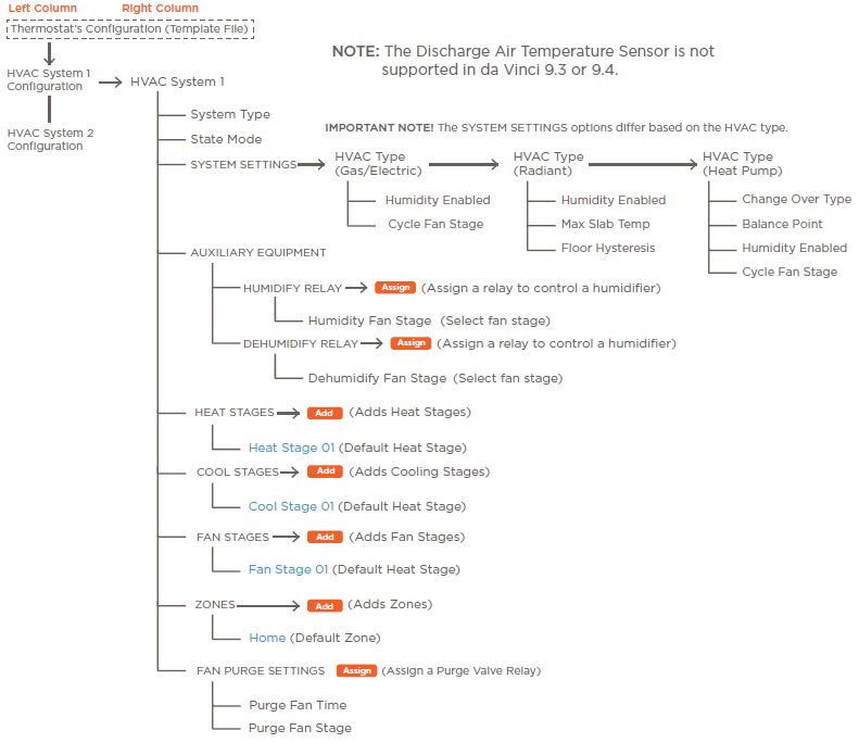
Section 4.1 above describes the various fields available in the web portal for configuring user interface settings on the thermostat. This section describes the web portal areas used to configure the functions of an HVAC system. Use the diagram below for reference when creating a configuration.
HVAC SYSTEMS
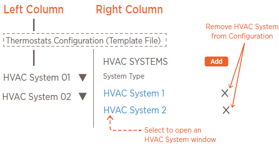
When adding one or more HVAC systems to a configuration, the thermostat controls one system, and the climate service in the Savant Pro App monitors and controls the additional HVAC systems. NOTE: A climate module with the necessary functionality is needed when adding more than one HVAC system to the configuration. See the Add an HVAC system to Configuration section below for information on adding HVAC systems to the configuration.
HVAC System <x>: Each HVAC system type (Gas, Electric, Heat Pump, Radiant) added to the configuration has its own set of parameters that may or may not need to be configured.
- Select the Add button to add a new HVAC system to the configuration.
- Select the X to remove any unwanted HVAC systems from the configuration.
- Select the Blue text to direct the user to a separate window that contains the fields tailored explicitly for the HVAC system selected.
SYSTEM TYPES AND MODES
Selecting an HVAC system (see image in previous section), opens a screen that contains the fields tailored explicitly to the HVAC system chosen. The first two fields are the System Type and State Mode and are described below.
- System Type: The type of HVAC system is displayed and can’t be modified (e.g. Gas, Electric, Heat Pump, Radiant).
- State Mode: In multi-zone systems, if calls for heating and cooling are initiated at the same time in different zones, the State Mode determines which takes precedence and executes first. Select one of the options below from the dropdown menu:
- Heat Before Cool: Satisfy the call for heat before starting a call for cooling. Any zone currently being cooled gets suspended until the zone calling for heat is satisfied.
- Cool Before Heat: Satisfy the call for cooling before starting a call for heat. Any zone currently being heated gets suspended until the zone calling for cool is satisfied.
- Biggest Difference: Satisfy the zone that is furthest away from the set-point temperature first.
SYSTEM SETTINGS
- Humidity Enabled: Reserved for future functionality. Not supported in version 0.1.0.
- Cycle Fan Stage: Select which fan stage will cycle the fan in the HVAC system on and off. The Fan Mode parameter on the thermostat hardware must be set to Cycle for this to function correctly. Cycle mode turns the fan on and off in 15-minute intervals when the stage selected is active.
AUXILIARY EQUIPMENT
The steps below assign a relay to control a humidifier or dehumidifier.
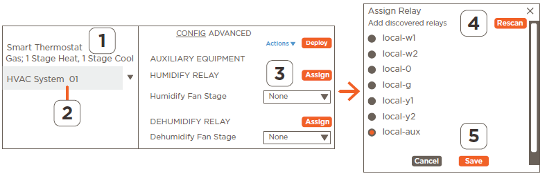
- Highlight the Smart Thermostat configuration file.
- Select an HVAC system. This opens a screen with parameters explicitly tailored to that system.
- Select the Assign button from the HUMIDIFY RELAY field.
- Select the Rescan button from the Assign Relay window that opens. The Rescan button will scan and discover all the relays in the system.
- Select the local-aux relay.
- Scroll to bottom of window and select Save.
HELPFUL
- The instructions assign control of the humidifier to the aux relay (local-aux), which is the relay typically used when controlling auxiliary equipment. However, any unassigned relay can be used.
- The Assign Relay window that opens in step 3 lists ALL the relays in the system, not just the available ones. It is up to the installer or integrator to keep track of the assigned and unassigned relays.
HEATING and COOLING STAGES
A heating or cooling stage is triggered when the thermostat initiates a call for heat or cooling. The thermostat evaluates and determines which stage of heating or cooling is required and makes the necessary selection. Customizing a heating or cooling stage is described below.
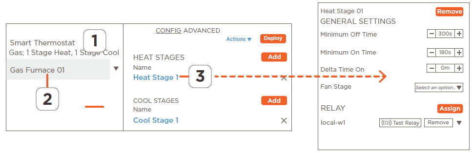
- Highlight the Smart Thermostat configuration file.
- Select the HVAC System. This opens a screen with parameters explicitly tailored to the HVAC system.
- Select the Heat or Cool stage. This opens a Heat or Cool stage screen.
- HELPFUL: By default, most configuration file templates have a heating and cooling stage available. This procedure modifies the preconfigured stages. However, additional heating or cooling stages can be added by selecting the ADD button associated with the heating or cooling field.
- Make the required modifications using the descriptions below.
- Minimum On Time: The amount of time that the heating or cooling stage must remain on once triggered. Default is 180 seconds and is configurable from 60-1200 seconds.
- Minimum Off Time: The amount of time that the heating or cooling stage must remain off once switched off. Default is 300 seconds and is configurable from 60-1200 seconds.
- Delta Time On: Sets a timer that determines how long, after stage 1 switches on, that stage 2 can be switched on. For example, with stage 1 running, stage 2 can’t switch on until the time set here expires (Range = 0-300 minutes).
- Relay: The appropriate relay for each stage is preassigned. To change the relay, select the Assign button and choose a different relay from the Assign Relay window that opens.
FAN STAGES
The thermostat determines when the fan stages are switched on and off. On the CLI-W210/200, the G relay is, by default, assigned to fan stage 1. Follow the instructions below to assign a different relay to a fan stage.
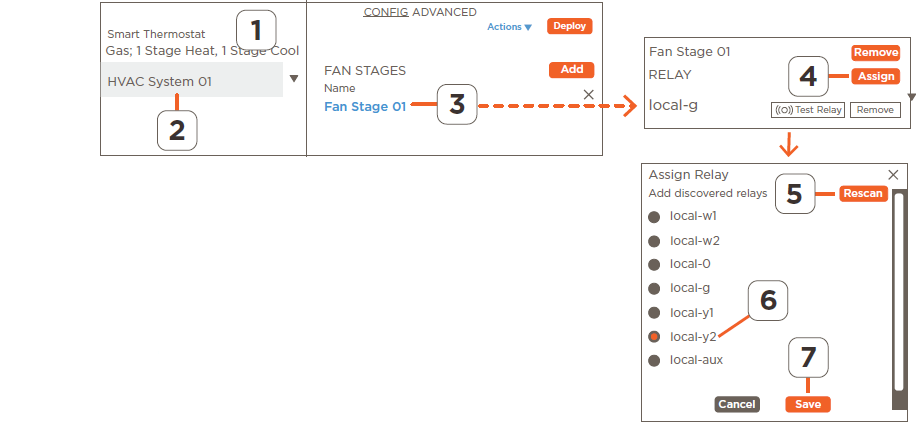
- Highlight the Smart Thermostat configuration file.
- Select the HVAC System.
- Select Fan Stage 01 (blue text) to link to the Fan Stage 1 screen.
- Select the Assign button. This opens the Assign Relay window.
- Select the Rescan button to scan and discover all the relays in the system.
- Select the desired relay from the list of discovered relays.
- Scroll down and select Save.
Additional Information
The procedure above describes how to modify an existing fan stage. If desired, a new fan stage can be created by selecting the Add button. Once the fan stage is created, a relay can be added using the steps described above.
FAN PURGE SETTINGS
Purging air from an HVAC system can occur for various reasons. Purging air uses a vent damper which controls the passing of air into and out of the system. Adding a fan purge relay to an HVAC system is optional. The instructions below describe how to configure the Purge Fan Settings.
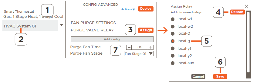
- Highlight the Smart Thermostat configuration file.
- Select the HVAC System.
- Select the Assign button from the Purge Valve Relay field.
- Select the Rescan button to scan and discover all relays in the system.
- Select a relay from the list of discovered relays.
- Scroll down and select Save.
- Set the following parameters
- Purge Fan Time: Set the time the fan will run during the purge cycle. Click the + or – button to increase or decrease the purge fan time.
- Purge Fan Stage: Select which fan stage will be running when the purge happens. Typical installations use fan stage 1, but the field is configurable to any stage available.
ZONES
A zone or section of a home or building that gets heated or cooled by the HVAC system and is typically sectioned by floor, room, or other means and identified accordingly (e.g., basement, 1st floor, second floor). Multiple zones can be added to each HVAC system. The section below describes how to access zone settings, with definitions for the relevant fields.
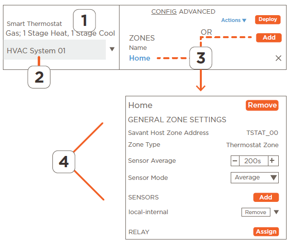
- Highlight the Smart Thermostat configuration file.
- Select the HVAC System.
- Select Home to open a window for a zone labeled Home. This zone is prebuilt and offered in most of the template configurations available.
- HELPFUL: By default, most configuration file templates have a zone labeled Home. In homes with only one zone, this is the only zone needed. In homes that require more than one zone, select the Add button to add a second zone.
- From the Zone screen, make changes to the following parameters as needed:
- Savant Host Zone Address: Each zone is identified with a read-only address and can’t be modified. The first zone added is addressed as zone 00. However, this same zone gets listed as zone 1 in the HVAC data table. The address shown in the web portal is labeled one less than that same zone listed in the data table.
- Zone Type: Is set to Thermostat Zone and can’t be modified.
- Sensor Average: Sets the amount of time allowed for the thermostat to collect a temperature sample from each sensor in that zone. The default is 200 seconds.
- Sensor Mode: In zones with multiple sensors, this field defines the way in which their readings are used to derive a single displayed temperature.
- Average: The average of the temperature samples collected from the sensors in that zone is calculated and displayed.
- Maximum: The highest temperature collected from all the temperature sensors in that zone is displayed.
- Minimum: The lowest temperature collected from all the temperature sensors in that zone is displayed.
- Sensors: To add one or more temperature sensors to zone, select the Add button. Select a sensor to add to the zone from the Add Sensor dialog that opens, select from the list of discovered sensors associated with the Sensor field. Refer to the Add or Replace a Temperature Sensor in a Zone section for information on adding sensors.
- Relay: To assign a relay to a zone that contains a zone damper, select the Assign button. Select a relay from the list of discovered relays. Refer to the Add a Relay to a Zone section for information on adding relays.
HELPFUL: Only the data collected from the sensors in the first zone are displayed on the thermostat. The data collected from any additional zones are managed by the thermostat but not displayed. A separate method would be required to view the actual temperature and humidity in the additional zones.
DISCHARGE AIR SENSOR
- Discharge Air Temperature Sensor functions are not supported in the 9.3 and 9.4 releases.
Examples
- Examples on how to configure the various functions on the thermostat are described in the sections below.
HVAC Template Files
Creating a custom configuration for one of the many types of HVAC systems can sometimes get daunting. Because of this, a list of template files that contain a configuration that can function with most HVAC systems are available. The templates cover the electric furnace, gas furnace, heat pump, and Radiant floor type systems.
NOTE: The instructions below describe how to add a template file when there is no file loaded. The process below assumes an IP Address was assigned to the thermostat and access to the portal was created (i.e. password created).
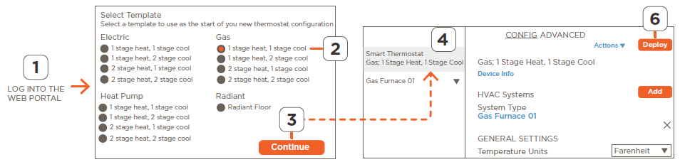
- Open and log into the web portal. With no file loaded, the Select Template screen opens.
- Select a template from the list of different HVAC types.
- Scroll down and select Continue and the template selected is then loaded into the web portal.
- Scroll through the various fields and make any modifications required. Use the descriptions fields from previous sections when making the changes.
- Once complete, select the Deploy button. A banner at the bottom of the web portal indicating the configuration is being sent to the thermostat is displayed.
- The thermostat will upload the file and then reboot to install the uploaded configuration. Upload times vary depending on the network. Typical upload and install times are less than one minute.
- Wake up the thermostat and verify the thermostat is working correctly.
HELPFUL INFORMATION
- When the thermostat already has a configuration loaded, to replace the existing configuration, select Actions > Start from Template from the thermostat’s configuration screen to open the Select Template screen. Once on the Select Template screen, any template file can be selected and deployed. Note that all existing parameters on the thermostat get replaced with the new template file’s attributes.
- Replacing a configuration on the thermostat deletes the existing configuration and sets any fields that are not compatible with the new configuration back to their default values.
Reset to Defaults
Follow the steps below to reset the thermostat to its factory default settings. The reset wipes out the configuration, removes the assigned IP address, and will need to be provisioned to the network again.
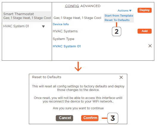
- Open and log into the web portal.
- Select Actions > Reset to Defaults from the configuration screen that opens.
- Read the Reset to Defaults alert window and select Confirm if you agree.
- After about a 10 second delay, the thermostat will reboot. Once the reboot is complete, the thermostat screen will open to the Select Network To Connect. Select the appropriate network to provision the thermostat to that network.
Renaming Fields
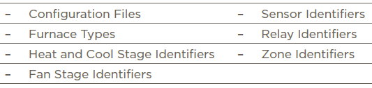
Renaming parameter headings is good practice and makes it easy to identify devices such as the thermostat, relays, sensors, zones, and furnace types, to name a few. The procedure below is performed on the configuration file name but it is relevant for any configurable heading.
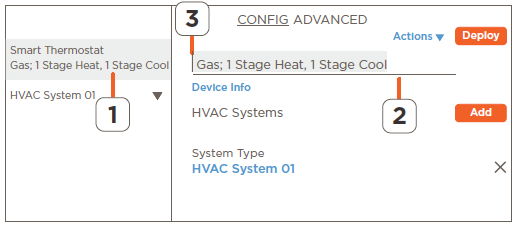
- Open and log into the web portal.
- Locate a heading that can be modified by hovering over the field to be renamed. If an edit line appears below the heading, the field can be modified.
- Highlight the heading and enter a new name. A list of fields that can be modified are shown below.
Add or Replace a Temperature Sensor in a Zone
For each zone to function properly, at least one temperature sensor must be configured to that zone. The process below adds a single sensor to an HVAC zone. The instructions assume a configuration file is loaded into the web portal.
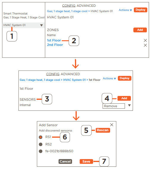
- From the web portal, select the HVAC system that is managing the zone.
- Scroll down and select the zone where the sensor is being added.
- Scroll to the SENSORS section.
- TIP: By default, The sensor internal to the thermostat is added to the first HVAC zone available. Because of this, a sensor may already be listed/configured to that zone.
- Select the Add button.
- In the Add Sensor window that opens, select Rescan and allow the portal to discover all sensors available.
- Select a temperature sensor from the Add Sensor window.
- Select Save and verify the sensor gets added to the SENSORS section.
- Optional: To remove any other sensors listed, select the Remove button associated with the sensor and follow the prompts. When there is more than one sensor listed under the SENSORS section, the thermostat will take readings from each sensor and output the average.
Additional Information
- To remove a sensor from a zone, select Remove from within the box associated with that sensor, and follow the prompts.
- When more than one temperature sensor is collecting data in a zone, either the average, maximum, or minimum of the sensors can be displayed.
- See the Zones section above information on setting the Sensor Mode field.
- The Sensor Average field increases or decrease the sample rate that the thermostat uses to collect data from each sensor. See the Zones section above for more information.
IMPORTANT: Auxiliary heat can’t be triggered by the balance point when the weather data is taken from the online weather app. The data must be taken from a sensor configured as an outdoor type sensor.
Calibrate a Sensors Output
When a sensor is not reading the exact temperature or humidity, an offset can be added to the data collected to display the temperature or humidity more accurately. Before starting the calibration process, Savant recommends placing a known good thermometer and humidity gauge near the thermostat to allow it to assimilate to the temperature and humidity in the room. Adding a correction offset to the data collected from a sensor within a zone is described below.
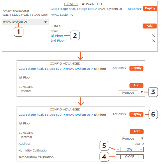
- From the web portal, select the HVAC system that is managing the zone where the sensor is located.
- Scroll down and select the zone that contains the sensor that needs the calibration.
- Scroll to the SENSORS section and locate the sensor. Select the drop-down arrow to open the calibration fields
- Compare the temperature displayed on the thermostat with the temperature from the known good thermometer and increase or decrease the temperature offset in the Temperature Calibration field.
- Repeat step 4 for humidity. Increase or decrease the offset in the Humidity Calibration field to correct the humidity data.
- HELPFUL: The humidity calibration field that is associated with any thermistor type sensors (internal, RSI, RS2) corrects the humidity collected from the humidity sensor embedded in the thermostat. The exception to this is when calibrating a 1-wire smart sensor like the CLI-THFM1. In this case, the humidity calibration field corrects the data collected from the smart sensor.
- Deploy the configuration to the thermostat and verify the offset corrected any discrepancies.
Additional Information
- Humidity calibration range = +/- 50%
- Temperature calibration range = (+/- 20°F, +/- 20° C)
- The blue text at top of screen is path to the zone. Select any of the text to link to that scree in the web portal
Add an Outdoor Sensor to the Configuration
How to configure one of the temperature sensors to collect and display the temperature outside is described below. When configured, the temperature is displayed above the indoor temperature on the thermostat’s LCD display.
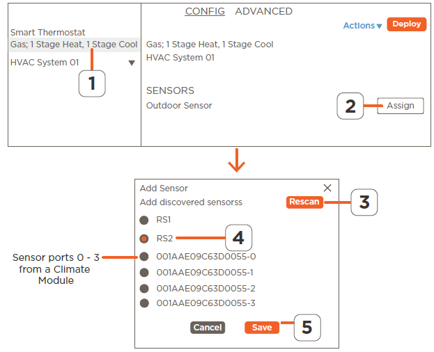
- From the web portal, select the configuration file or template file.
- Scroll to the SENSORS section and select the Assign button associated with the Outdoor Sensor field.
- Select the Rescan button from the window that opens, and the web portal will scan for any available temperature sensors.
- Select one sensor from the Assign Sensor window that opens.
- Select Save and the sensor selected gets added as a outdoor sensor.
- Deploy the configuration to the thermostat and verify the outside temperature is displayed.
Additional Information
- Only 10KΩ type sensors can be configured as outdoor sensor.
- Sensors connected to a climate module port are presented with the UID of the climate module along with the port number. Refer to image above.
- When the weather forecast feature is enabled:
- The temperature data collected from an outdoor sensor overrides the temperature sent from the online weather app.
- When no outdoor sensor is configured, the temperature sent from the online weather app is displayed as the outdoor temperature.
- In systems set up with a heat pump and auxiliary heat, Savant recommends configuring an outdoor sensor. The data from the outdoor sensor gets compared to the temperature set in the balance point field.
- When the outside temperature goes below the value specified in the balance point field, auxiliary heat is triggered.
Add a Smart Sensor to a Zone
Smart sensors such as the CLI-THFM1 collect both temperature and humidity from one sensor. Follow instructions below to add this type of sensor to an HVAC zone.

- From the web portal, select the HVAC system that is managing the zone.
- Scroll down and select the zone where the sensor is being added.
- Scroll to the SENSORS section and select the Add button.
- In the Add Sensor window that opens, select Rescan and allow the portal to discover all sensors available.
- Select the smart sensor from the list of discovered sensors
- Select Save and verify the sensor gets added to the SENSORS section.
- Deploy the configuration to the thermostat and verify the temperature and humidity are displayed on the thermostat.
Test Sensor Function
After adding a smart sensor to a zone, a Test Sensor button appears with the sensor in the portal. Select the Test Sensor button, and a red LED on the face of the sensor will light, indicating its position in the zone. Select the button again to switch the LED off.
Additional Information
- As shown in the image above, smart sensors present themselves with the UID of the sensor.
- A Smart sensors can’t be configured as an outdoor sensor.
Add an HVAC system to the Configuration
The CLI-W210/W200 thermostat alone can control one HVAC system. By default, all the template files available already include an HVAC system and does not require one to be added. Adding a second or third HVAC system is only necessary when a climate module that controls a separate HVAC system gets added. The steps below describe how to add a second HVAC system to a configuration.
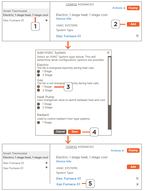
- From the web portal, select the configuration or template file.
- Select the Add button linked to the HVAC Systems field.
- Select the HVAC system from the Add HVAC System that opens.
- Select the Save button, and the HVAC system gets added. See the image to the right.
- Select the HVAC system just created and make any necessary modifications.
- Deploy the updated configuration to the thermostat.
Additional Information
- Each HVAC system has its own preset configuration.
Assign an Aux Relay to Control a Humidifier or Dehumidifier
When controlling an external dehumidifier or humidifier, a relay must be assigned to trigger the external equipment to switch on and off. The instructions below assign the auxiliary relay to do this; however, any available relay can be used. Before starting the process, verify the humidifier is installed and wired, and with the CLI-W200, a smart sensor that monitors humidity must also be wired and configured (CLI-THFM1). Adding a smart sensor is described in the Add a Smart Sensor to a Zone section above. See the Multistat Smart Thermostat Deployment Guide (009-1959) on the Savant Community for wiring and installation information.

- From the web portal, select the configuration file.
- Slide the Humidity Enabled field button to the right to enable humidity on the thermostat.
- Select the HVAC system that will control the external equipment.
- Under the AUXILIARY EQUIPMENT section, select the fan stage that triggers the fan in the HVAC system to come on when the humidifier or dehumidifier switches on.
- Select the Assign button linked to the Humidify or Dehumidify Relay field.
- Select the auxiliary relay from the Assign Relay window that opens.
- Select Save to add the relay to the Humidify or Dehumidify Relay field.
- Deploy the updated configuration to the thermostat and verify the system performs as intended.
Additional Information
- The humidifier and fan stage 1 switch on automatically once the humidity decreases five percentage points (-5%) below the humidity set point. For example, when the humidity setpoint is at 30%, the humidifier will switch on at 25% and switch off at 30%.
- Follow these same instructions when configuring a dehumidifier. The difference is the Dehumidify Fan Stage and Dehumidify Relay fields get configured.
- The instructions above set up the auxiliary relay. However any relay can be used.
- The Assign Relay window that opens in step 2 lists all the relays in the system, not just the available ones. It is up to the installer or integrator to keep track of the used and unused relays.
Hysteresis
Setting Hysteresis in a Radiant Flooring HVAC System with Slab Sensor Installed
In a radiant flooring installation, the Floor Hysteresis field adds a buffer to the Max Slab Temp field which will reduce the number of times the HVAC system switches on and off. The Max Slab Temp field is set as a safety so the temperature in the floor never goes above a specified temp. As an example, if the Max Slab Temp is set to 90° F and the Floor Hysteresis field is set to 4° F, the HVAC system will stop supplying heat when the floor reaches 90° F and not switch back on until the temperature at the slab sensor reaches 86° F. The instructions below describe how to set up these two fields. It is important to note that the Slab Sensor, Max Slab Temp, and Hysteresis parameters are optional. These parameters are for safety purposes and a Radiant system will still function with these parameters not set.
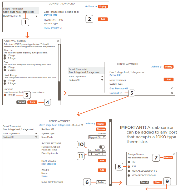
- Add Radiant HVAC System.
- Select the Configuration Template file loaded in the web portal.
- Select the ADD button associated with the HVAC Systems field to add a Radiant HVAC System to the configuration.
- Select the Radiant HVAC System.
- Select Save and the Radiant HVAC System gets added.
- Select the Radiant System just added. This opens a window with fields explicitly for the Radiant HVAC System.
- Add Slab Sensor to Radiant HVAC System.
- Select the Assign button from the Slab Temp Sensor field.
- Select the Rescan button to discover all sensors in the system.
- Select which port has the slab sensor connected.
- Select Save to assign the port to the slab sensor field.
- Configure Max Slab Temp
- Using the + and – buttons, set the Max Slab Temp to the maximum temperature the floor should reach. This is a safety feature to ensure the floor never goes above this temperature.
- Configure Hysteresis
- Using the + and – buttons, set the Floor Hysteresis temperature. The number set allows the temperature of the floor to fall until the following is met (Max Slab Temperature – Hysteresis). At that point, the HVAC system will switch back on to supply heat to the floor. See the example in the overview text at the top of this.
HELPFUL: The Floor Hysteresis value is always subtracted from the maximum slab temperature.
Climate Module
Add a Temperature Sensor and a Relay to a Zone
This example describes how to add a second zone to an existing configuration and in that zone, do the following:
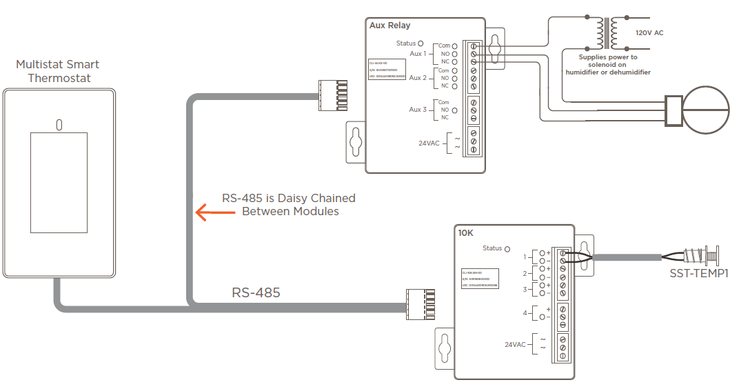
- Add a temperature sensor, that is wired to a CLI-10K4IN climate module, to the configuration.
- Assign a relay from a CLI-AUX3 climate module and use it to control a humidifier or dehumidifier.
It is important to note that the starting configuration was from the template file labeled Gas; 1 stage Heat, 1 stage Cool and some of the functionality is already built into this file. Use the diagram below as a reference as it represents what is being added to the configuration file.
IMPORTANT: The procedure assumes the climate modules are wired and powered. Refer to the Quick Reference Guide to each module for wiring information.
Assign Temperature Sensor to Zone
The instructions below assign the temperature sensor connected to the CLI-10K4IN climate module to the zone labeled Home. This zone is by default set in the configuration and available for use. If desired, a zone other than this preconfigured zone can be used. In this case, a new zone will need to be created. Refer to the ZONES section above for information on this.
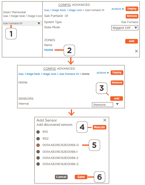
- Select the <HVAC system> that the temperature is being added. These instructions use the default HVAC system labeled Gas Furnace 01.
- Scroll to the ZONES heading, select the zone where the sensor will be added.
- From the zone window that opens, select the Add button associated with the SENSORS field.
- Select the Rescan button from the Add sensor window that opens to discover all ports that could have a sensor wired to it.
- Select the port, from the climate module, where the sensor is wired. Climate module ports are identified by the UID of the climate module followed by the port number.
- Example: 001AAE08F65D0061-0 = Port 0 of climate module with UID shown.
- Select Save to add the sensor to the SENSORS section.
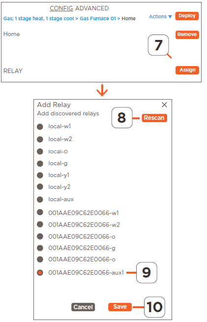
- Any unwanted temperature sensors listed can be removed. To do this, select the Remove button associated with the sensor and follow the prompts.
- HELPFUL: Refer to the Add or Replace a Temperature Sensor in a Zone section for more information on adding relays to a zone.
- Add Auxiliary Relay to Zone: The previous section adds a temperature sensor to the zone labeled Home. The next step in the example is to add an auxiliary relay from a CLI-AUX3 climate module to the same zone. When complete, the temperature sensor monitors the temperature in that zone. When the temp falls below the setpoint, the aux relay is triggered, and it opens or shuts a damper that feeds the zone.
- HELPFUL: Refer to the Add or Replace a Temperature Sensor in a Zone section for more information on adding relays to a zone.
- From the same zone, select the Assign button associated with the RELAY field to open the Assign Relay window.
- Select Rescan to discover all ports on the devices in the system that have a relay linked to it.
- Select the auxiliary relay port from the climate module. As described above, the port is identified by the UID of the module followed by the name of the port on that module.
- Scroll to the bottom and Save the updates. The window will close and the aux1 relay connection is added to the RELAY section.
Climate Module
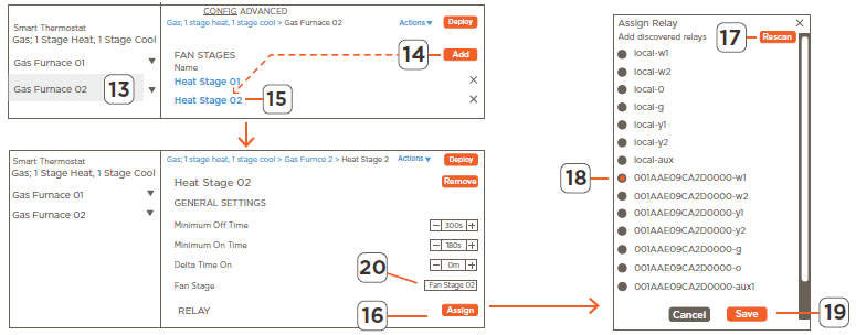
Add a Second HVAC System
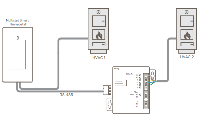
The CLI-W210/200 thermostat can control one HVAC system. Managing more than one system requires the Pro App and a climate module such as the CLIREL1AUX1 or CLI-PTACK1. The steps below describe how to utilize the ports from the CLI-REL1AUX1 module to add a second HVAC system. The climate relays in the thermostat are used to manage one HVAC System, and the climate relays in the CLI-REL1AUX1 climate module manage the other. The example below assumes the module is wired and powered. Refer to the Relay Module with one 6-Port Climate Relay and one Aux [CLI-REL1AUX1] Quick Reference Guide on the Savant Community for more information. Use the diagram below as a reference as it represents what is being added to the configuration file.
Add a second HVAC System
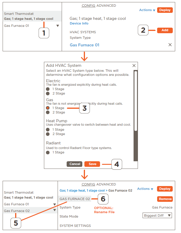
- Select the Smart Thermostat configuration file.
- Select the Add button linked to the HVAC SYSTEMS heading.
- Select the type of HVAC System from the Add HVAC System window that opens.
- Select Save and the new HVAC System gets added to the configuration.
- OPTIONAL: To update the name given to the new HVAC System, select the newly added HVAC system from the left column, highlight it in the right side column, and enter the new name.
- Rename to a label that identifies the new HVAC system.
- HELPFUL: Refer to the Add an HVAC System to the Configuration section above for more information.
- Add a Fan Stage and Assign a Fan Relay
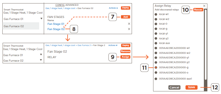
- Add a Fan Stage and Assign a Fan Relay
- HELPFUL: Refer to the Add an HVAC System to the Configuration section above for more information.
- With the new HVAC system highlighted, select the Add button linked to the FAN STAGES field.
- Select the Fan Stage added to open its configuration window.
- Select the Assign button linked to the RELAY field.
- In the Assign Relay window that opens, select the Rescan button to discover all the relays available on all devices.
- Select the port from the climate module. The relay linked to this port will manage the fan.
- Scroll down and select Save to add the relay to the fan stage (not shown in the image).
- Select to revert back to the HVAC System field.
-
- Add a Heating Stage, Assign a Heating Relay, Configure Relay
-
- Select the Add button linked to the HEAT STAGES field to add a second Heat Stage.
- Select the Heat Stage added to open its configuration window.
- Select the Assign button linked to the RELAY field.
- Select the Rescan button to discover all the relays available on all devices.
- Select the port from the climate module. The relay linked to this port will manage the heat stage added.
- Scroll down and select Save to add the relay to the heat stage (not shown in image).
- Select the fan stage created above.
- Configure the remaining fields from the Heat Stage window. Refer to the descriptions in the HEATING AND COOLING STAGES section above.
- Select to revert back to the HVAC System field.
-
- Add a Cooling Stage and Assign a Cooling Relay
-
- Repeat steps 14 – 22 and add a cooling stage.
- When complete, the updates can be Deployed to the thermostat.
ADVANCED Tab
The ADVANCED tab in the web portal represents the configuration file that gets uploaded to the thermostat. Each line in the ADVANCED tab represents a field in the CONFIG tab. This tab is available for advanced users only and is typically used to troubleshoot issues that might arise. Savant recommends that users consult Savant Support before making updates. When making updates to the configuration, Savant recommends making the updates in the user-friendly interface available from the CONFIG tab.
Important Notice
Disclaimer
- Savant Systems, Inc. reserves the right to change product specifications without notice, therefore, the information presented herein shall not be construed as a commitment or warranty.
- Savant Systems, Inc. shall not be liable for any technical or editorial errors or omissions contained herein or for incidental or consequential damages resulting from the performance, furnishing, reliance on, or use of this material.
Patents
- Certain equipment and software described in this document is protected by issued and pending U.S. and foreign patents.
- All products and services are trademarks or registered trademarks of their respective manufacturer.
Copyright
- This document contains confidential and proprietary information protected by copyright. All rights reserved.
- Copying or other reproduction of all or parts of this document is prohibited without the permission of Savant Systems.
Trademarks
© 2020 Savant Systems, Inc. All rights reserved. Savant, Savant App, TrueImage, Savant Host, Now You Can, RacePoint Blueprint, Single App Home,
TrueCommand, TrueControl, and the Savant logo are trademarks of Savant Systems, Inc. AirPlay, Apple, AirPort Express, AirPort Extreme, Apple TV, Apple Remote Desktop, FireWire, iMac, iTunes, iPad, iPad mini, iPad Air, iPhone, MacBook, Mac and OS X are trademarks or trade names of Apple Inc. iOS is a trademark of Cisco®. Android, Google, Google Play, and other Google marks are trademarks of Google, Inc. Wi-Fi is a registered trademark of the Wi-Fi Alliance®. HDMI® is a trademark of HDMI Licensing, LLC. MOTU® is a registered trademark of Mark of the Unicorn, Inc. Luxul is a registered trademark of Luxul Wireless. NETGEAR®, the NETGEAR Logo and ProSAFE are trademarks of NETGEAR, Inc. Extreme™ is a trademark of Extreme Networks, Inc.
All other brand names, product names, and trademarks are the property of their respective owners.
Technical and Sales Support
Savant Systems, Inc. is dedicated to providing prompt and effective support in a timely and efficient manner.
- To contact Savant Support, access the Savant Customer Community and enter a support Case ticket.
- To contact Savant Sales, visit Savant.com and select Contact Us to locate a local sales representative in your area.
CONTACT
- 009-1973-01 | 201209
- 45 Perseverance Way, Hyannis MA 02601
- Savant.com
- 508.683.2500
Copyright © 2020 Savant Systems, Inc.
Reference
Download Manual:
Savant CLI-W210 Smart Programming Thermostat User Guide
Other Manual:
Savant CLI-W210 Smart Programming Thermostat Product Specification Guide