Saswell SAS900MTK-2 Programmable thermostat
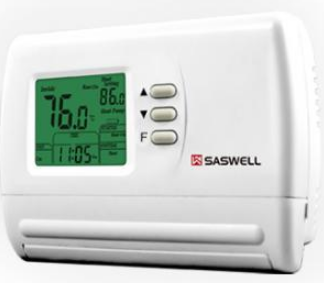
Installation and Operation Manual
Specification
- Power Supply: 20VAC-30VAC 50-60HZ or Battery powered.
- Terminal Load: 1.0A per terminal, 3.0A maximum total load
- Set Point Temp. Range: 45ºF to90ºF (7ºC to 32ºC).
- Accuracy: +/- 1ºF or +/- 0.5ºC.
- Dimensions: 5.1” W X 3.7” H X 1.2” D
- Color: White
FEATURES
- Large LCD display with backlight, continuous backlight option.
- Simultaneous heat and cool set point storage.
- Display of room temperature set temperature and current time simultaneously
- Fan switch with ON and AUTO.
- Permanent user setting retention during power loss. No batteries are required.
- Optional “AAA” batteries provide continuous time and temperature display during power loss.
- Optional temperature display of Fahrenheit or Celsius scale.
- Air Filter change Indicator.
- Compressor short cycling protection is available.
IMPORTANT SAFETY INFORMATION
- Always turn off power at the main power source by removing the fuse, or switching the circuit breaker to the off position before installing, removing, cleaning, or servicing the thermostat.
- Read all of the information in this manual before installing this thermostat.
- Use a professional contractor to install this thermostat.
- This is a 24VAC low-voltage thermostat. DO NOT INSTALL ON VOLTAGES HIGHER THAN 30 VAC.
- ALL wiring must conform to local and national building and electrical codes and ordinances.
- Do not short (jumper) across terminals on the gas valve or at the system control test installation.
- This will damage the thermostat and void the warranty.
- Do not switch the system to cool if the temperature is below 50ºF (10ºC). This can damage the air conditioning system.
- This thermostat will not control your heating/air conditioning system without power.
- Two“AAA” alkaline batteries are only used to provide continuous time and temperature display during power loss. Installed batteries will allow programming prior to installation.
- Replace batteries when the battery icon indicates a low battery message.
- Change the air filter when the Filter Change Icon begins blinking.
- Use this thermostat only as described in this manual.
REMOVE THE OLD THERMOSTAT
- Turn off power at the main service panel by removing the fuse or switching the appropriate circuit breaker to the OFF position before removing the existing thermostat.
- Turn off power to the heating and cooling system by removing the fuse or switching the appropriate circuit breaker off.
- Remove the cover of the old thermostat. This should expose the wires.
- Label the existing wires from the existing thermostat before removing them.
- After labeling the wires, remove the wires from the wire terminals.
- Remove the existing thermostat from the wall.
- Refer to the following section for instructions on how to install this thermostat.
THERMOSTAT BUTTONS AND SWITCHES-
- Raises temperature setting
- Powers temperature setting
- Selects clock set mode, Indicates filter time remaining, and selects menu items in the configuration menu
- Fan control switch (ON, AUTO) 5 System control switch (COOL, HEAT, OFF)

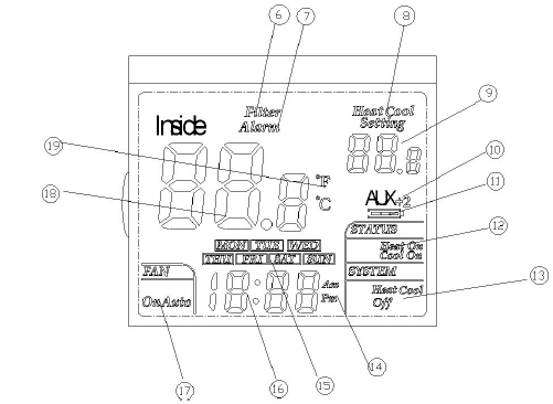
THERMOSTAT LCD DISPLAY
- Filter Alarm: Indicates filter needs to be replaced. 7 Alarm: When flashing, indicates a system malfunction
- Heat Setting: Temperature set-point in the Heating Mode Cool Setting: Temperature set-point in the Cooling Mode
- Set-point temperature display
- NO Icon indicates when the thermostat is in the 1st stage heat pump mode. AUX +2 indicates when the thermostat activates auxiliary heating
- Battery Icon: If the Battery Icon is flashing, batteries need to be replaced.
- Indicates the thermostat is calling for HEAT or COOL
- Indicates the current system switch position
- Clock AM/PM indicator 15 Indicates the current day, or days being programmed
- Indicates the current time of day or time of days being programmed.
- Indicates the current fan switch position.
- Indicates the current actual room temperature, or the current configuration menu number.
- Indicates whether the displayed temperature is in ºF or ºC
INSTALL THE THERMOSTAT
ATTACH THERMOSTAT BASE TO WALLPULL THE COVER OFF THE BASE.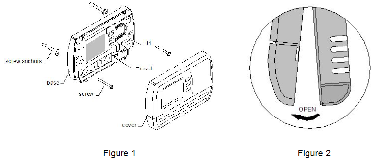
- Turn off power to the heating and cooling system by removing the fuse or switching the appropriate circuit breaker off.
- place the system switch (COOL/OFF/HEAT) in the OFF position.
- Place the FAN (AUTO/ON) switch in the AUTO position.
- Gently pull the cover straight off the base. (See figure 2.) 5. Put the thermostat base against the wall where you plan to mount it. (Be sure the wires will feed through the wire opening in the base of the thermostat.)
- Mark the placement of the mounting holes.
- Move the base out of the way. Drill mounting holes. Use a hammer to tap in the supplied anchors into the mounting holes.
- Fasten the base loosely to the wall as shown in Figure 1, using two mounting screws. Placealevel against the bottom of the base and adjust until level, then tighten the screws. (Levelingisfor appearance only, and will not affect thermostat operation.)
- Insert stripped, labeled wires into matching wire terminals. See “Wiring Diagrams”, Section3, Figure 3
- tighten the screws on the terminal block. Gently tug on each wire to be sure of the proper connection. Double-check that each wire is connected to the proper terminal.
- Install two fresh “AAA” alkaline batteries in the battery compartment. Be sure to match the positive (+) ends of batteries with positive (+) battery terminals in the battery compartment. (The thermostat will operate from 2 sizes of “AAA” alkaline batteries or 24VAC power. When operated from 24VAC power, your thermostat will maintain time and continuously display the temperature during a loss of AC power with the batteries installed).
- Replace the cover on the thermostat by snapping it in place.
- Turn on power to the system at the main service panel.
ELECTRIC/GAS JUMPER (Fan Option)
Read the following information before clipping the non-electric heat jumper 1 (See figure 1). If you are unsure of your application, contact a qualified service person. This thermostat is configured from the factory to energize the fan on a call for heat. If your system is an electric heat that REQUIRES the thermostat to turn on the fan on a call for heat, place do not cut Jumper1.If your system does not require the thermostat to energize the fan on a call for heat such as fossil fuel (gas,oil, etc.), forced air system as well as hydraulic heating systems, place cut the jumper1.
BATTERY OPERATION-
The thermostat is powered by 24VAC. Batteries are not required for proper operation, but with two“AAA” batteries installed, your thermostat will maintain time and continuously display the temperature during a loss of power
WIRING DIAGRAMS-
CHECK THERMOSTAT OPERATION
If at any time during testing your system does not operate properly, contact a qualified service person. Turn on the power to the system
FAN OPERATION
Move the system switch to the OFF position. If your system does not have a“G” (Fan)terminal connection, skip to the Heating System. 1. Move the fan switch to the ON position. The blower should begin to operate. 2. Move the fan switch to the AUTO – position. The blower should stop immediately.
HEATING SYSTEM
- Move the SYSTEM switch to the HEAT position. If the auxiliary heating system has a standing pilot, be sure to light it.
- Press ▲ to adjust the thermostat setting above room temperature. The 1-stage heating should begin to operate.
- Both stages of the heating system will begin to operate when the set point is 3℉(2℃) above ambient. AUX +2 display will be shown. If +2 is flashing, the second stage will delay 15 minutes before starting. (See configuration menu 2)
- Press ▼ to adjust the temperature setting below room temperature. The heating systems should stop operating.
COOLING SYSTEM
- To prevent compressor damage, if the outdoor temperature is below10ºC(50ºF), DO NOT operate the cooling system. Move the SYSTEM switch to the COOL position.
- Press ▼ to adjust the thermostat setting below room temperature. The blower should come on immediately, followed by cold air circulation. If the COOL ON display is flashing, the stage compressor is at off-time cycle protection
Both stages of the cooling system will begin to operate when the set point is 3℉(2℃) below the ambient AUX +2 display will be displayed. If the +2 display is flashing, the second stage will delay 15 minutes before starting (Note: See Configuration menu item1) - Press ▲ to adjust the temperature setting above room temperature. The cooling systems should stop operating. If all functions operate properly, the thermostat is installed correctly.
REPLACING BATTERIES
If your thermostat was pre-installed, the batteries may be in place. If the battery icon on the display is flashing, it indicates that the batteries need to be replaced. When the thermostat is powered only by battery, the battery icon will flash for approximately 2 months before the batteries are expected to expire.
Important: Replace the batteries when the low battery message flashes on the display. This will keep the thermostat operating properly. With two “AAA” batteries installed, your thermostat will maintain time and continuously display the temperature during the loss of AC power
- Place the COOL/OFF/HEAT switch in the OFF position.
- Put the FAN AUTO/ON switch in the AUTO position.
- Gently pull the cover straight off the base.
- Install two “AAA” alkaline batteries in the battery compartment.
- Be sure to match the positive (+)ends of the batteries with the positive (+) terminals as marked in the battery compartment.
- It may take as long as 30 seconds for the low battery icon to disappear after changing
CONFIGURATION AND OPERATION
Configuration Menu
The configuration menu allows you to set certain thermostat operating characteristics to your system or personal requirements. Move the SYSTEM switch to the OFF position, then press and hold the▲▼buttons at the same time for 5 seconds to enter the configuration menu. The display will show the first item in the configuration menu. Press the button to move to the next menu item. Use the ▲ and ▼ buttons to select. To revert to factory default settings, press the RESET button (See Fig. 1). All users’ changed settings will revert to factory default settings. To exit the configuration menu and return to normal operation, move the SYSTEMswitchtothe HEAT or COOL position. If no buttons are pressed within 30 seconds, the thermostat will exit the configuration menu. The configuration menu chart summarizes the configuration options. An explanation of each option follows.
| Step | Press Buttons | Displayed (Factory Defaults) | Press ▲ or▼ to select | Description |
| 1 | ▲▼5 seconds | CC (FA) | FA or SL | Select fast cooling or slow cooling |
| 2 | HC (FA) | FA or SL | Select fast heating or slow heating | |
| 3 | bL (2) | 1 – 3 | Select display backlight mode | |
|
4 |
FL(00) |
00-12 |
Select filter time in months. A
selection of “00” deactivates the filter feature. |
|
| 5 | FC (F) | F or C | Select ºC or ºF Readout | |
| 6 | CL (0) | +4 TO -4 | Select temperature calibration point up to 4º higher or 4º lower. | |
| 7 | CP (5) | 0 or 5 | Compressor Lockout delay time.0 = none ; 5 = 5 Minutes | |
|
8 |
AU(2) |
2 or 10 |
Aux Heat or cool offset 2 = 2º F below “Y” on
10 = 10º F below “Y” on |
|
|
9 |
Move System
switch to either heat or cool position. |
RETURNS TO
NORMAL OPERATION |
Select the cooling cycle rate
The FA setting is used to produce shorter cooling cycles. The SL setting produces a longer cooling cycle. Both settings produce very accurate temperature control and can be set to your personal preference. FA cycles the system at a 0.5ºF (0.5ºC) differential, andAuxcooling at 2.0ºF high first stage on. SL cycles the system at 1.5ºF (1.5ºC) differential, and Aux cooling at 2.0ºF high first stage on. The default setting is FA. 2.
Select heating cycle rate
The FA setting is used to produce shorter heating cycles. The SL setting produces a longer heating cycle. Both settings produce very accurate temperature control and can be set to your personal preference. FA cycles the heat pump system at a 0.5ºF differential andAuxheating at 2.0ºF below the first stage. SL cycles the heat pump system at a 1.5ºFdifferential, and Aux heating at 2.0ºF below the first stage on. The default setting is FA. 3
Select display backlight
The display backlight improves display contrast in low lighting conditions. Select 1 for the NObacklight display. Select 2 for the backlight to come on for approximately 30 seconds when any button of the thermostat is touched. Select 3 for the backlight to remain on continuously.The default setting is “2”. NOTE: When operated from batteries (No “C” terminal connection, or if AC power goes off), the LCD display backlight will be disabled regardless of which configuration number is selected
Select filter replacement run time
The thermostat will display the Filter Alarm after a set time of operation. This is a reminder to change or clean your air filter. This time can be set from 00 to 12 months in 1-month increments. Selection of 00 WILL CANCEL THIS FEATURE. When Filter Alarmisdisplayed, you can clear it by pressing the ” ” button (To enter the filter program) and then holding the▲and ▼ buttons. This resets the timer and starts counting the days until the next filter change. The default setting is “00”. 5.
Select ºF or ºC readout
Change the display readout to Centigrade or Fahrenheit as required. The default setting is “F”. 6.
Select temperature recalibration
This feature allows you to adjust the displayed room temperature up to 4º higher or lower. Your thermostat can be accurately calibrated to match your previous thermostat. The current or adjusted room temperature will be displayed on the display. The default setting is “0”. 7.
Select compressor lockout delay
To protect the compressor from short cycling, you can select compressor off-time cycle between 0 and 5 minutes. When the thermostat compressor time delay occurs, the Cool On or Heat On display will flash during the compressor lockout. The default setting is “5”.
Select aux heating or cooling conditions
Users can select “2” or “10” according to personal requirements. If you select 2℉, the thermostat will determine whether to activate or deactivate the auxiliary system by comparing the set temperature and room temperature. If the room temperature is 2℉higher than the set temperature in cooling or2℉ lower than the set temperature in Heating, the thermostat will activate auxiliary cooling mode or heating mode. If the room temperature is the 0℉-2℉higherthan setting temperature in cooling or 0℉-2℉ lower than setting temperature inHeating. the thermostat is in the 1st stage of heating or cooling mode.
MANUAL OPERATION
TEMPERATURE OVERRIDE
- Press the ▲ and ▼ buttons until the temperature you want is displayed. The thermostat will override the current programming and keep the room temperature at the selected temperature until the next program period begins. Then the thermostat will automatically revert to the program.
CHECK COUNT BACK FOR FILTER REPLACEMENT
- a) When in configuration the selections are in months, each month’s selections are equal to 30 days.
- b) To review the remaining days, long hold the ” ” button.
- c) To reset the filter days – long hold the ” ” button (to enter the filter program) and then hold the ▲ and ▼ buttons. This resets the timer and starts counting the days until thenext filter change. S
SET THE CURRENT DAY AND TIME
- a) Shortly press the button. The display will show the hours numbers flashing.
- b) Press and hold either the ▲ or ▼ button until the correct hour and AM/PMdesignatorisreached. (AM begins at midnight, PM begins at noon).
- c) Press the button again. The display will show the minute’s numbers flashing.
- d) Press and hold either the ▲ or ▼ button until the correct minutes are reached. e) Press the button again. The display will show the day of the week flashing.
- f) Press and hold either the ▲ or ▼ button until the correct weekday is selected. g) Press the button once. The display will now show the correct day of the weekend the correct time
TROUBLESHOOTING
If a voltage spike or static discharge blanks out the display or causes erratic thermostat operation, you can reset the thermostat by pressing the reset button (See Figure 1). If the thermostat has power, and has been reset and still does not function correctly, contact your heating/cooling service contractor
| Symptom | Possible Cause | Corrective Action |
| No Heat/No Cool/No Fan | 1. Blown fuse or tripped circuit breaker
2. Furnace power switches to OFF. 3. Furnace blower compartment door or panel loose or not properly installed |
Replace fuse or reset breaker. Turn switch to ON
Replace door panel in proper position to engage safety interlock or door switch. |
| Step | Press Buttons | Displayed (Factory Defaults) | Press ▲ or▼ to select | Description |
| 1 | ▲▼5 seconds | CC (FA) | FA or SL | Select fast cooling or slow cooling |
| 2 | HC (FA) | FA or SL | Select fast heating or slow heating | |
| 3 | bL (2) | 1 – 3 | Select display backlight mode | |
|
4 |
FL(00) |
00-12 |
Select filter time in months. A
selection of “00” deactivates the filter feature. |
|
| 5 | FC (F) | F or C | Select ºC or ºF Readout | |
| 6 | CL (0) | +4 TO -4 | Select temperature calibration point up to 4º higher or 4º lower. | |
| 7 | CP (5) | 0 or 5 | Compressor Lockout delay time.0 = none ; 5 = 5 Minutes | |
|
8 |
AU(2) |
2 or 10 |
Aux Heat or cool offset 2 = 2º F below “Y” on
10 = 10º F below “Y” on |
|
|
9 |
Move System
switch to either heat or cool position. |
RETURNS TO
NORMAL OPERATION |
| No Heat | 1. Pilot light not lit.
2. System switch not set to Heat 3. Loose connection to thermostat or system 4. Furnace Lockout Condition. Heat may also be intermittent 5. Heating System Requires service or thermostat requires replacement. |
Relight Pilot
Set System Switch to Heat and raise set point above room temperature Verify thermostat and system wires are securely attached Many furnaces have safety devices that shut the system down when a lockout condition occurs. If the heat works intermittently, contact the furnace manufacturer or local service person for assistance. Diagnostic: Set System Switch to Heat and raise the Setpoint above room temperature. Within a few seconds the thermostat should make a soft click sound. This sound usually indicates the thermostat is working properly. If the thermostat does not click, try the reset operation listed above. If the thermostat does not click after being reset, contact your heating and cooling service person or place of purchase for replacement. If the thermostat clicks, contact the furnace manufacturer or a service person to verify the heating system is operating correctly. |
| No Cool | 1. System Switch not set to Cool
2. Loose Connection to thermostat or System 3. Compressor lock-out is activated. |
Set system switch to Cool and lower set point below room temperature.
Verify thermostat and system wires are securely attached. Wait five minutes until the compressor protection time is up. There may be up to a five minute delay before the thermostat can activate the compressor if the compressor lock-out option is selected in the configuration menu. |
WARRANTY POLICY
Only cataloged products sold to distributors are warranted to the original purchaser, and to be free from defects in material and workmanship, for a period of one (1) year from the date of purchase, unless specified in writing for a different period. Prior to returning this product to us, the purchaser shall give notice in writing stating how this product fails to fulfill this warranty. No product shall be accepted for repair or replacement without required written notice and without prior written authorization and shipping address having been received by the purchaser. Only our factory is authorized to perform services under this warranty. Transportation charges are to be prepaid by the purchaser. This warranty does not extend to any product that has been subjected to misuse, abuse, neglect, accidents, alternations, improper installation or use in violation of the printed instructions furnished by us. This warranty neither applies to batteries, not deterioration of, nor damage to the product caused by the use of faulty batteries.
WE SHALL NOT IN ANY EVENT BE LIABLE FOR ANY INCIDENTAL OR CONSEQUENTIAL DAMAGES
.This warranty gives you specific legal rights, and you also have other rights which vary from state to state. Some states do not allow the exclusion or limitation of incidental or consequential damages, or implied warranties, so the above limitations or exclusion may not apply to you.
Reference:
DOWNLOAD MANUAL:
Saswell SAS900MTK-2 Programmable thermostat Operating Instruction

Saswell SAS900MTK-2 Programmable thermostat Operating Instruction