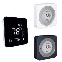
Salus WSG-M4 Wireless HVAC Thermostats
Introduction
Using this Manual
For the latest Instructions go to: WWW.SALUSINC.COM To cover all SALUS Wireless Products without requiring customers to download unnecessary documentation, the Wireless System Guide has been divided into 5 volumes. Volume 1 is required for all wireless systems since it covers the installation of the SG888ZB Gateway and the SALUS Smart Home application. The remaining volumes are specific to a particular group of controls. Below is a description of several icons used to direct the reader’s attention.
Special Attention Boxes
This manual uses special attention icons to alert the reader of important safety concerns, information important to the reliable operation of the controls or helpful installation/setup information.
 Safety
Indicates a condition that may cause severe personal injury, death, or major property damage
 Important Information
Indicates information that requires special attention for the correct operation of the control
 Your Benefit
Indicates helpful installation or setup information
System Overview
SALUS-connected HVAC control systems use Zigbee-based communications protocol to provide a universal language for smart components to work together seamlessly and securely with an internet connection. If the internet connection is interrupted or disconnected, the HVAC component will continue to operate together.

By connecting the SG888ZB Gateway to your home network, the system is connected to the world wide web. Monitor or adjust your HVAC system from anywhere via the SALUS Smart Home application. If the connection to the internet is lost, the system continues to function with the settings selected.
Included Parts

Tools Required

Installation – Mounting & Wiring
BEFORE BEGINNING the installation procedure, turn off the power to the heating system.
Step 1. Determine the desired wiring configuration for the ST880ZB Thermostat. The following chart shows the terminal designations for gas, electric or oil (Non-HP) and heat pump (HP)
installations. Appendix A provides reference wiring diagrams for typical thermostat installations.
| Table 2.1: ST880ZB Optima Zigbee Thermostat Wiring Reference | |||
| Gas, Electric or Oil (Non-HP) | Heat Pump (HP) | ||
| RC | 24 VAC for Cooling System | R | 24 VAC for Heat Pump |
| RH | 24 VAC for Heating System | — | Jumper to R |
| C | 24 VAC Common Return | C | 24 VAC Common Return |
| — | Reserved | L | System Monitor |
| Y1 | Single / 1st Stage Cooling | Y1 | Single / 1st Stage Compressor |
| Y2 | 2nd Stage Cooling | Y2 | 2nd Stage Compressor |
| W1 | Single / 1st Stage Heating | W1 | Emergency Heat |
| W2 | 2nd Stage Heating | O/B | Changeover Valve |
| G | Fan Signal | G | Fan Signal |
| — | Reserved | — | Reserved |
Step 2. If replacing an existing thermostat, review and record the existing wiring configuration:
- Remove the thermostat from the wall to expose the wiring terminals
- Take a photograph or note the wire colors and designations (see wiring reference above)
- Attach wire labels provided to each of the existing thermostat wires
Step 3. Remove existing thermostat
Step 4. Install the Mounting Plate.
Use the wall anchors and screws supplied with the Optima Thermostat to attach the Mounting Plate to the wall, making sure the wires go through the center opening.
Step 5. Attach wiring to the Mounting Plate.
To cover screw holes or paint disturbance from the old thermostat, install the Trim Plate between the wall and the Mounting Plate. The Trim Plate can be mounted vertically or horizontally.
Step 6. Install batteries in the Thermostat or remove the battery tab.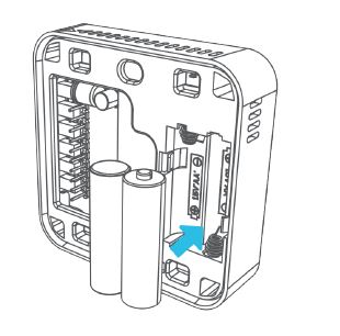
Match each wire to the intended terminal.
- Open the terminal by lifting the latch
- Insert the wire into the terminal
- Push the latch down to secure the wire
Refer to the wire tags, wiring schematic, and/or photograph taken earlier if necessary. If the batteries are not installed, install them in the Thermostat, observing the CORRECT POLARITY.
- Use alkaline batteries (low battery sensor is tuned to alkaline batteries.
- DO NOT Mix old and new batteries
- DO NOT Mix Alkaline, Ni-Cad, or Lithium batteries
Step 7. Configure the initial parameters

Step 8. Attach the Thermostat to the Mounting Plate
- Align connector pins and retention posts
- Push the Thermostat onto the Mounting Plate
- BE SURE that the connector pins are not bent
- BE SURE that the Thermostat is FULLY SEATED on the Mounting Plate
Controls & Display

| Control | Regular Mode | Installation Mode |
| Slider Ring | Clockwise – Increment Value
Counter-clockwise – Decrement Value |
Clockwise – Next Option-
Counter-clockwise – Previous Option |
| – / Previous | Decrement Value | Previous Option |
| + / Next | Increment Value | Next Option |
| Fan / Hold / Back | Select Fan Mode
Hold when adjusting temperature |
Back to Previous Menu |
| Mode / Enter | Select Operating Mode | Select Displayed Option |
| Reset | Reset to default state (requires pin or paperclip) | |
Home Screen

| Display Indicator | Description |
| Room Temperature | Room temperature at the thermostat sensor |
|
Heat/Cool Icons |
Indicates the state of the appliance Cooling demand is active
Heating demand is active If neither icon is shown, there is no appliance activity |
| Radio Icon | Indicates that the thermostat is connected to a Smart Home system |
| Low Battery | Indicates that the batteries require replacement |
|
Fan Mode |
Manual Fan Override
Auto – Fan based on Heat/Cool activity On – Fan is always On |
| Day of the Week | Displays the day of the week (M Tu W Th F Sa Su) |
| Time | Displays the current time in 12 or 24 hour format |
|
Fan Indicator |
Indicates Fan State Fan On
No fan indicator is shown when the fan is off |
| Temperature Set Point | Displays the target temperature |
| Message Display | Displays the thermostat state, menu or options |
|
System Mode |
Operating mode for the appliance
Off – Appliance is off Cool – Appliance is set to cooling mode Heat – Appliance is set to heating mode EmHeat – Emergency Heat Mode (heat pump only) |
Pairing Instructions
While the Optima Zigbee Thermostat doesn’t need to be installed to be paired with an SG888ZB Universal Gateway, it should be at or near the intended installation location to account for potential signal interference.

Step 5. Open the SALUS Smart Home application, select the drop-down menu from the upper right of the screen and select: All Devices Add New Device
ST880ZB Optima Zigbee Thermostat

Time & Date
The ST880ZB Optima Thermostat should be configured by an experienced or authorized installer.

| Table 2.1: Time Zones | |
| NST1 | Newfoundland Standard Time |
| AST1 | Atlantic Standard Time |
| EST | Eastern Standard Time |
| CST | Central Standard Time |
| MST | Mountain Standard Time |
| PST* | Pacific Standard Time |
| AKST | Alaska Standard Time |
| HST | HawaiiStandard Time |
Step 1. After pressing MODE to illuminate the screen and prepare the ST880ZB for input. Press
and hold the MODE button for 3 seconds to enter the configuration menu. will appear on the screen.
Step 2. Release and press the MODE button again to adjust the time zone. The default is can be changed by pressing + or -. See the time zone chart above for the time zone settings available. Press Mode to accept the value and the screen will advance to 12- or 24-hour display format selection.

Step 3. Use the +/- buttons to change between 12- and 24-hour display formats. Press MODE to accept.
Step 4. The display shows the time with the hours flashing. Use the +/- buttons to change the hour value noting the correct am/pm designation. Press MODE to accept.
Step 5. When the minutes are flashing, use +/- to update the minute’s display. Press MODE to accept the value and proceed to set the date.
Step 6. When DATE is displayed, the Month value (M) begins flashing. Use the +/- buttons to adjust the month. Press MODE to confirm.
Step 7. Set the Day (D) and Year (Y) similarly, pressing MODE to advance. After Day and Year are set, the DST (Daylight Savings Time) option is displayed.
Step 8. Use the +/- buttons to toggle between DST ON and DST OFF. Press MODE to confirm.
Settings

Step 1. Press and hold the MODE button on the ST880ZB Thermostat for 3 seconds to enter the configuration menu. will appear on the screen. Press + once to advance to
Step 2. Press MODE to enter the SETTINGS Menu, using +/- to cycle through COUNTRY, HVAC TYPE, TEMP UNIT, OFFSET, and SPAN. See the chart below for available options.
Table 2.2: ST880ZB Optima Zigbee Thermostat – SETTINGS
| Table 2.2: ST880ZB Optima Zigbee Thermostat – SETTINGS | |||
|
COUNTRY |
US | United States of America | |
| CA | Canada | ||
|
HVAC TYPE |
HP |
O – Rev Valve | Energized in Cooling (default) |
| B – Rev Valve | Energized in Heating | ||
|
NON-HP |
FAN HG | Fan operation for gas heating (default) | |
| FAN HE | Fan operation for electric/oil heating | ||
| TEMP UNIT | °F or °C | Fahrenheit or Celsius | |
| OFFSET | -7°F to +7°F
(-4°C to +4°C) |
Calibration offset: Value is added to the sensed temperature | |
|
SPAN |
0 .5°F to 2 .0°F
(0 .25°C to1 .00°C) |
Thermostat dead band – ex . Setpoint of 70°F with Span of 1°F
– Temperature will fall to 69°F without activating heat . Tempera- ture will rise to 71°F without activating cooling . |
|
Firmware Update
After pressing the MODE button to illuminate the screen, and preparing the ST880ZB for input, press & hold MODE for 3 seconds. When appears on the screen, press the – button 2 times (or the + button 3 times) to advance to . Press MODE, is displayed indicating an update is in progress. Once the Thermostat returns to the home screen, the update has been loaded.
Factory Reset
When resetting the Optima Thermostat to its factory default settings, it is necessary to delete the device from the SALUS Smart Home Application.
Step 1. Choose tile icon corresponding to the Optima ST880ZB Thermostat and choose the title from the upper left corner when the tile flips.
Step 2. Choose “Remove shared room thermostat” after scrolling to the bottom of the screen.
Step 3. Choose “Delete” from the dialog box.
Step 4. Press the MODE button to illuminate the screen, preparing the ST880ZB for input. Then press and hold MODE for 3 seconds.
When appears on the screen, press the – button 1 time (or the + button 4 times)
Step 5. Press + and the Thermostat will be reset to factory defaults. After resetting, the Optima Thermostat will begin the startup procedure as if it were first powered. After entering the required information, it will begin the pairing process.
Note: The ST880ZB can be reset using a pin or paper clip to press the button on the bottom of the Optima Thermostat. However, this will not clear the country, time zone, temperature units, HVAC system type or networking information.
Included Parts

Tools Required
Installation – Mounting & Wiring
BEFORE BEGINNING the installation procedure, turn off the power to the heating system.
Step 1. Determine the desired wiring configuration for the ST880ZB Thermostat. The following chart shows the terminal designations for gas, electric or oil (Non-HP) and heat pump (HP) installations. Appendix A provides reference wiring diagrams for typical thermostat installations.
| Table 2.1: ST880ZB Optima Zigbee Thermostat Wiring Reference | ||
| Gas, Electric or Oil (Non-HP) | Heat Pump (HP) | |
| RjP | Power Jumper (RH) | |
| RC | 24 VAC for Cooling System or Jumper to RjP | |
| RH | 24 VAC for Heating System | 24 VAC for Heat Pump |
| C | 24 VAC Common Return | |
| Y1 | Single / 1st Stage Cooling | Single / 1st Stage Compressor |
| Y2 | 2nd Stage Cooling | 2nd Stage Compressor |
| W1AX | Single / 1st Stage Heating | Auxiliary or Emergency Heat |
| W2OB | 2nd Stage Heating | Changeover Valve |
| G | Fan Signal | |
| L | Reserved | System Monitor |
Step 2. If replacing an existing thermostat, review and record the existing wiring configuration:
- Remove the thermostat from the wall to expose the wiring terminals
- Take a photograph or note the wire colors and designations (see wiring reference above)
- attach wire labels provided to each of the existing thermostat wires
Step 3. Remove the existing thermostat.
Step 4. Install the Mounting Plate.
Use the wall anchors and screws supplied with the Optima Thermostat to attach the Mounting Plate to the wall, making sure the wires go through the center opening.
Step 5. Attach wiring to the Mounting Plate. To cover screw holes or paint disturbance from the old thermostat, install the Trim Plate between the wall and the Mounting Plate. The Trim Plate can be mounted vertically or horizontally.Match each wire to the intended terminal.
- Push the latch to the right of the terminal to be connected
- Insert the wire into the terminal and release the button
- If properly engaged, the button will remain slightly depressed when released
Refer to the wire tags, wiring schematic, and/or photograph taken earlier if necessary.
Step 6. Remove the battery tab to activate the batteries
The Optima S Thermostat will prioritize power from the AC connection (RC to C). If AC power is not available, the device will switch to the internal batteries. If the batteries are not installed, install them in the Thermostat, observing the CORRECT POLARITY.
- Use alkaline batteries (low battery sensor is tuned to alkaline batteries)
- DO NOT Mix old and new batteries
Display Screen Boot Sequence
When power is first applied to the Optima S Thermostat, the following boot sequence is displayed.

Pairing Instructions

After the boot sequence is completed, the Optima S will enter pairing mode. A 10-minute countdown timer will begin, waiting to connect to the network. When the Thermostat finds a network, times out after 10 minutes or pairing is cancelled by the user, the timer will begin Initial Configuration, described later in Section 3.

Step 1. Open the SALUS Smart Home application, select the drop-down menu from the upper right of the screen, and select: All Devices Add New Device

Step 2. Press Scan Devices.
After pressing “Scan Devices”, the SALUS Smart Home application scans for devices.
Step 3. Choose the check box that corresponds to the device to pair.
Step 4. Enter a unique descriptive name to identify each device. Press “Next”.
Step 5. Press “Please click here to set up”.
Step 6. Choose from setup options specific to the device. Press “Complete set up”.
Step 7. Press “Finish” to complete the pairing.
Initial Configuration

After pairing is complete, the ST898ZB Thermostat begins a configuration procedure

Non-Heat Pump Options

Heat Pump Options

- After the initial configuration is complete the Thermostat will display the Home Screen
- The Thermostat is now ready to be attached to the Mounting Plate

Step 8. Attach the Thermostat to the Mounting Plate

- Align connector pins and retention posts
- Push the Thermostat onto the Mounting Plate
- BE SURE that the connector pins are not bent
- BE SURE that the Thermostat is FULLY SEATED on the Mounting Plate
- Turn on the power to the HVAC System.
Home Screen & Controls


Operation
Without further configuration, the Optimal S Thermostat can be used as a manual thermostat. To access enhanced features, additional settings must be configured. See Configuring the Thermostat later in this section for more details. The SALUS Smart Home system can be used to set up a schedule on the device. Instructions for this are provided in Section 4, Thermostat Schedules. Display timeout: The Optima S display turns off after a short time to conserve energy and minimize nighttime distractions. The default timeout is 10 seconds, but the time can be adjusted in the configuration menu.
Changing the Setpoint: To change the setpoint, simply touch the + button to increase or the – button to decrease the target temperature. While adjustments are being made, the room temperature will be shown in Time Display and the current setpoint will be in the Main Temperature Display area. The message display will indicate which set point is being adjusted. Touch the Main Temperature Display to save the value or simply wait 3 seconds until the screen times out and returns to the Home screen.
Permanent Hold: To hold the temperature at a specific target, ignoring automated changes from the SALUS Smart Home application (discussed in Section 4), change the setpoint as shown above and press the Permanent Hold Icon on the Fan Button while the setpoint temperature is displayed on the Main Temperature Display. The Permanent Hold Status Icon appears next to the Main Temperature Display, indicating Permanent Hold is active. To cancel Permanent Hold, press + or – to activate the set point adjustment screen and press the Permanent Hold Icon. The Permanent Hold Status Icon is removed, and the Thermostat will follow an external schedule if set up.The set point is adjusted by 1°F (0.5°C) for each button press. The Optima S maintains a minimum temperature difference between the Heating and Cooling set points [Default 3°F (1.5°C)]. If the set point being changed gets too close, the other setpoint will be adjusted to maintain the separation.
Configuration
Instructions for Thermostat configuration are intended for qualified installation/service professionals. Do not make adjustments without a thorough understanding of the HVAC system. Pressing the Settings Icon will begin cycling through all available configuration settings and three setup functions.
- Press
 the Settings Icon to move to the next parameter or function
 - Press and hold for approximately 1 second to go to the previous screen
- To change a value, use the + or – Icons
- To save a value, press to move on to the next screen or press any non-icon area to return to the
Home Screen. The value will also be saved if the display times out after 10 seconds.
Settings / Functions
Functions

Settings / Functions (Continued):

Optima & Optima S Parameters – Smart Home
Module 1 of the SALUS Wireless System Guide provides information about downloading and using the SALUS Smart Home application from your computer or smart device. 
Step 1. Press On the SALUS Smart Home dashboard, and click the tile that represents the desired thermostat.
Step 2. When the tile flips, choose the device description in the upper left corner.
Step 3. Choose the setup icon to access the parameters.
Step 4. Scroll down to the parameter list boxes.
Step 5. Choose a parameter to change and select the desired value.
Step 6. Click “Save” when changes are complete.
Schedules & Status Options – Smart Home
Using the SALUS Smart Home application, users can choose between setting up temperature schedules and using the Status to determine the temperatures. This process is the same for both the ST880ZB, Optima, and ST898ZB, Optima S, Thermostats. The following shows how to change between Schedule (the default value) and Status.

Step 1. On the SALUS Smart Home dashboard, click the tile that represents the desired thermostat.
Step 2. When the tile flips, choose the device description in the upper left corner.
Step 3. Scroll down to the “Preferences” section of the screen.
Step 4. Select “Change to Status” and select “Yes” to change all thermostats to schedule.
Step 5. Click “Yes” to change all thermostats to Status.
Step 6. Choose the button that corresponds to “Use Status” to finalize the change.
Use a similar process to change back to “Linked to Schedule”. Individual thermostats can be set differently if accessed from the menu under Status.
Schedule Setup – Smart Home

Step 1. On the SALUS Smart Home dashboard, click the tile that represents the desired thermostat.
Step 2. When the tile flips, choose the device description in the upper left corner.
Step 3. Scroll down to the “Preferences” section of the screen.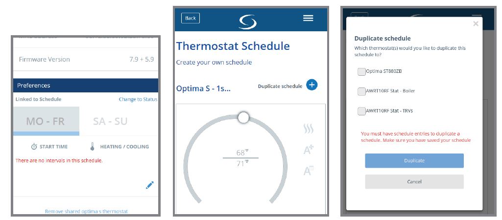
Step 4. Choose the icon to edit the schedule. To duplicate a schedule of another thermostat on the network, press “Duplicate schedule”. A list of thermostats available to duplicate, similar to the above, will appear. Simply choose the desired thermostat.
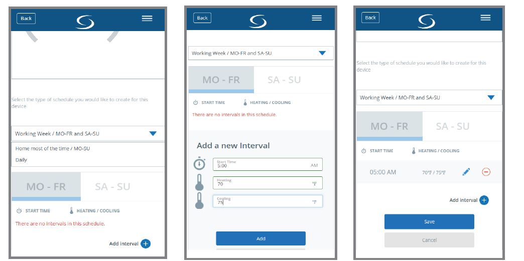
Step 5. Select the type of schedule desired and then press “Add interval”
Step 6. Enter the Start Time along with the target set point for both Heating and Cooling.
Step 7. Choose “Add Interval” to enter the next temperature change time and set point temperatures. Up to 6 intervals can be added for a daily cycle.

Step 8. Click “Save” once the Schedule is complete. Then, choose another tab, depending on the type of schedule.
Step 9. Repeat adding intervals for each available tab.
Step 10. When all desired schedules have been entered, press “Save”.
Status for Thermostat Control – Smart Home

Step 1. On the SALUS Smart Home dashboard, click the menu.
Step 2. Scroll down to the Status group of menu items.
Step 3. Choose a status for which to change the temperature values. Choose a status for which to change the temperature values.
Step 4. Choose “Thermostats” from the House Check tab.
Step 6. Change the Heating and Cooling setpoints to the desired value
Step 5. Choose the desired Thermostat.

Step 7. Select “Back” to return to the menu.
Step 8. Repeat these steps for each remaining Status.
Selecting Current Status

Troubleshooting Information
- The thermostat does not call for heat and/or cooling.
- Check that connector pins are straight and intact
- Check that the thermostat is fully seated on the mounting plate. If the terminals are not fully engaged, the firmware cannot activate the relays. This prevents power surges to the HVAC system.
- The heating and cooling demands are reversed.
- Check that the thermostat is configured properly: Heat Pump (HP) or Furnace/Air Conditioner (NON-HP). If the Heat pump checks that the O/B Configuration under SETTINGS is correct.
- Check that the wiring is correct, especially the Y and W wires. If used with a Heat Pump, check that the O/B wire is correct.
- The fan does not turn on.
- Check that the wiring is correct, especially the G wire.
- If heating with oil or gas, make sure the furnace is working. In gas heat mode (HG), the fan is
controlled by the furnace to avoid supplying cold air when the unit is starting.
- The display does not appear after the batteries have been replaced.
- Press the reset button on the bottom of the thermostat with a pin, straightened paper clip or similar object.
REFERENCE
Download Manual
Salus WSG-M4 Wireless HVAC Thermostats Installation Guide
