Salus ST101ZB Low Voltage Fan Coil Thermostat
Introduction
Fan Coil Thermostat System Overview
The SALUS fan coil thermostats provide remote control of fan coil units via the SALUS Smart Home application for smart devices and PCs. Detailed instructions for the SALUS Smart Home application are available in the SG888ZB Pairing Guide.

Product Safety Information
Please read these instructions carefully BEFORE INSTALLING AND USING the Fan Coil Thermostat. DO NOT supply line voltage (120 or 240 VAC) to an ST101ZB Low Voltage Fan Coil Thermostat.
- DO NOT cover any of the vents on the thermostat
- DO NOT place the unit in a bathroom or area of excessive moisture
- DO NOT allow the unit to get wet. This device serves as a temperature control system only in dry, closed living and office spaces.
- DO NOT use solvents or aggressive cleaning agents. A dry, soft cloth is recommended for cleaning.
The manufacturer does not accept responsibility for any damage caused by not following these instructions.
Codes & Regulations: Installation and setup of this product must be performed in strict compliance with national, state/province, and local codes. Additional code requirements for line voltage-powered devices may apply to the ST100ZB Line Power Fan Coil Thermostat. An authorized, the qualified installer may be required.
Intended Use: SALUS ST100ZB/ST101ZB Fan Coil Thermostats are intended for interior room temperature control in conjunction with fan coil heating systems only. Other uses are not recommended or supported.
Installer or Contractor: Record parameters at startup and any subsequent parameter changes in the installer notes section of this manual.
ST100ZB Line Power Fan Coil Thermostat
Be sure that all parts listed are included and available before starting installation.
Included Parts – ST100ZB Line Power Thermostat

Tools – Required/Optional
Required Tools:
- #1 Phillips or flathead screwdriver
Optional Tools:
- Smartphone or digital camera for wiring reference photos
- Small screwdriver for removing wiring from old thermostat terminals
Before beginning the installation procedure, turn off the power to the fan coil system.

Remove the Existing Wired Thermostat
- Step 1. If replacing an existing wired thermostat, review and record the wiring configuration of the existing thermostat:
- Remove the existing thermostat from the wall to expose the wiring terminals
- Take a photograph or note the wire colors and connections (see wiring reference table below)
- Attach wire labels to each of the wires
Terminal Wire Color Function4 Pipe System 2 Pipe System L Black 120/240 VAC Line Power 120/240 VAC Line Power N White 120/240 VAC Neutral 120/240 VAC Neutral Gl Red Fan – Low Speed Fan – Low Speed Gm Blue Fan – Medium Speed Fan – Medium Speed Gh Brown Fan – High Speed Fan – High Speed WY Orange Heating Valve Actuator Heat/Cool Valve Actuator YA Yellow Cooling Valve Actuator Auxiliary Heat Ac Accessory Contact Accessory Contact Ac Accessory Contact Accessory Contact Tp Supply Pipe Temp . Sensor Supply Pipe Temp . Sensor Tx External Temp Sensor External Temp Sensor Ts Temperature Setback Temperature Setback Tc Tp/Tx/Ts Common Tp/Tx/Ts Common
- Step 2. Label each wire when disconnecting them from the thermostat terminals and remove the thermostat mounting plate (if necessary).
Paint the mounting surface, if desired, before mounting the thermostat back plate to ensure complete wall coverage.
A split junction box may be required in some jurisdictions to separate line voltage supply wires from low-voltage sensor leads.
ST100ZB Fan Coil Thermostat Installation
- Step 1. Install the Wiring Mount in the desired location using the junction box screws provided, making sure the wires go through the center opening. An optional wall plate (sold separately) is available for mounting to other junction box configurations (see below).


- Step 2. Connect wiring to the ST100ZB Back Plate – Use the following chart to identify the desired configuration.
Configuration L N Gl Gm Gh WY YA Ac Ac Tp Tx Ts Tc* 2-Pipe Heat Only 
W o o o o o o 2-Pipe Cool Only Y o o o o o o 2-Pipe Heat/Cool Manual Changeover W/Y o o o o o o 2-Pipe Heat/CoolSeasonal Changeover W/Y o o P o o P 2-Pipe Heat/Cool w/Auxiliary Heat W/Y A o o P o o P 4-Pipe Heat/Cool w/Manual or Auto Changeover W Y o o o o o Required / o=Optional / W=Heat Valve Actuator / Y=Cool Valve Actuator / A=Auxiliary Heat
* If using more than one (Tp/Tx/Ts) terminal, it may be necessary to splice Tc.
- Step 3. Attach Thermostat to the wiring mount by aligning the connector pins.
Remove any unused, pre-wired leads or add wire nut cap to isolate line voltage.
Make sure the connector pins are not bent and that the Thermostat is fully seated on the wiring mount.
Be sure that all parts listed are included and available before starting installation.
Included Parts – ST101ZB Low Voltage Thermostat

Tools – Required/Optional
- Required Tools:
- #1 Phillips or flathead screwdriver
- Drill with 3/16” bit if wall anchors are required
Optional Tools:
- Smartphone or digital camera to take photos of wiring for later reference
- Screwdriver to disconnect wires from existing thermostat
- Pencil for capturing wires
Before beginning the installation procedure, turn the power off to the fan coil system.
Remove the Existing Wired Thermostat
| Terminal | Wire Color | Function | |
| 4 Pipe System | 2 Pipe System | ||
| R | Black | 24 VAC Input | 24 VAC Line Power |
| C | White | 24 VAC Common | 24 VAC Common |
| Gl | Red | Fan – Low Speed | Fan – Low Speed |
| Gm | Blue | Fan – Medium Speed | Fan – Medium Speed |
| Gh | Brown | Fan – High Speed | Fan – High Speed |
| WY | Orange | Heating Valve Actuator | Heat/Cool Valve Actuator |
| YA | Yellow | Cooling Valve Actuator | Auxiliary Heat |
| Ac | Accessory Contact | Accessory Contact | |
| Ac | Accessory Contact | Accessory Contact | |
| Tp | Supply Pipe Temp . Sensor | Supply Pipe Temp . Sensor | |
| Tx | External Temp Sensor | External Temp Sensor | |
| Ts | Temperature Setback | Temperature Setback | |
| Tc | Tp/Tx/Ts Common | Tp/Tx/Ts Common | |
| Step 1. Remove the existing thermostat from the wall to expose the wiring terminals.Step 2. Photograph the wiring connections for future reference
Step 3. Label each wire according to its terminal attachment Step 4. Carefully remove the wires and any existing mounting plate.
|
|||

ST101ZB Low Voltage Fan Coil Thermostat Installation
- Step 1. Use the included wall screws and/or anchors to attach the wiring mount to the wall, making sure the wires go through the center opening. If alternate mounting holes are required, use a wall plate (sold separately.)


- Step 2. Attach the wires to the matching terminals based on the fan coil configuration as follows:
Configuration R C Gl Gm Gh WY YA Ac Ac Tp Tx Ts Tc* 2-pipe Heat Only W O O O O O O 2-pipe Cool Only Y O O O O O O 2-pipe Heat or Cool – Manual Changeover W/Y O O O O O O 2-Pipe Heat or Cool – Seasonal Changeover W/Y O O P O O P 2-Pipe Heat or Cool w/ Auxiliary Heat W/Y A O O P O O P 4-Pipe Heat/Cool Manual or Auto Changeover W Y O O O O O =Required / o=Optional / W=Heat Valve Actuator / Y=Cool Valve Actuator / A=Auxiliary Heat
* If using more than one (Tp/Tx/Ts) terminal, it may be necessary to splice Tc.
SS909ZB Optional Temperature Sensor
Be sure that all parts listed are included and available before starting installation.
SS909ZB Temperature Sensor

Tools – Required
#1 Phillips flathead screwdriver
SS909ZB Temperature Sensor Installation
The SS909ZB Temperature Sensor should be located at a point where the temperature is to be used to control the fan coil thermostat. This temperature sensor can be permanently mounted on a wall or on the desk stand provided. If mounted on the desk stand, the SS909ZB can be moved to different locations to provide maximum comfort. For instructions on connecting the temperature sensor to a Fan Coil Thermostat, refer to Section 5.0 – Joining & Pairing.
- Step 1.
Remove the Wall Plate from the back of the SS909ZB Temperature Sensor.
- Step 2.
Attach the Wall Mount in the desired location using the screws and anchors provided.
- Step 3.
Slip the SS909ZB Temperature Sensor onto the Wall Mount.
Desktop Mounting – SS909ZB Temperature Sensor
- Step 1.
Remove the Wall Plate from the back of the SS909ZB Temperature Sensor.
- Step 2.
Slip the SS909ZB Temperature Sensor onto the Desk Mount.
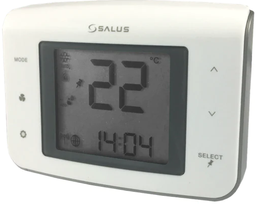
Fan Coil Thermostat Display & Keypad


Device Joining & Pairing
Fan Coil Thermostat – Preparation for Joining the Network
After installing the Fan Coil Thermostat and any optional SS909ZB Temperature Sensors, turn on electrical power to the fan coil system and Fan Coil Thermostat.
When the Fan Coil Thermostat is first powered, all segments will be briefly displayed. The display will then show the firmware version.
If the Fan Coil Thermostat is not connected to a network, the device will display and a 10 minute countdown timer will start.
Joining the SG888ZB Gateway Network

- Step 1.
Open the SALUS Smart Home application, select the drop-down menu from the upper right of the screen, and choose: All Devices Add New Device Scan Devices - Step 2.
Check the box corresponding to the appropriate Fan Coil Thermostat and press “Connect equipment.”
- Step 3.
Enter a unique name for the device and press “Next.” - Step 4.
Press the icon to enter ‘setup’ mode

- Step 5.
Make desired changes to setup. Scroll down and choose “Complete set up”.
- Step 6.
Choose “Finish”
Device Joining & Pairing
- Once the Fan Coil
The thermostat is successfully paired with a gateway, the device will briefly display the Zigbee channel.
- Next, the Fan Coil Thermostat enters Parameter Setup. Use the SELECT key to scroll through available parameters (See Appendix A) and to make changes.

- Press the key to enter the operation screen.
Optional SS909ZB Temperature Sensor Pairing
- Step 1.
Press and Hold the and keys simultaneously on the Fan Coil Thermostat to display the screen above for entering Special Function Codes.
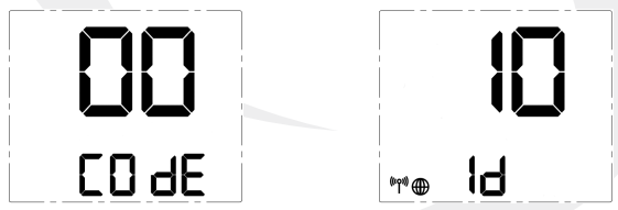
- Step 2.
Make sure the screen reads 00 COdE and press SELECT to enter the Identify Mode.An A10-minute countdown timer begins. - Step 3.
Remove the SS909ZB Remote Temperature Sensor from the Wall Plate or Desk Stand.
- Step 4.
Use a small screwdriver to remove the face plate from the Remote Temperature Sensor and pull the battery tab. - Step 5.
When the battery tab is removed, the red LED will begin to flash.

- Step 6.
Open the SALUS Smart Home application, select the drop-down menu from the upper right of the screen and choose: All Devices Add New Device Scan Devices The sensor will automatically initiate an operation to associate it with the Fan Coil Thermostat that is in Identify Mode.
 - Step 11.
If the Fan Coil Thermostat is set to EXT, Parameter P12 is set to 1 (Zigbee remote sensor) and the temperature display shows “- -“ instead of a temperature value, do the following to be sure the SS909ZB
Temperature Sensor is paired with the Fan Coil Thermostat.
Configuration
Pressing the SETTINGS button will allow adjustment of user-selectable settings.


Special Function Codes
To access special functions, press and hold the ![]() keys simultaneously. Use the and keys to scroll through the available codes.
keys simultaneously. Use the and keys to scroll through the available codes.

Operation
Operating Modes
The Fan Coil Thermostat can be operated in Standalone Mode, Local Mode or Simple Mode depending on the network and internet connection. The chart below shows how these modes affect the display and operation of the device.
Table 7.1: Operating Modes
| Operation | Standalone Mode | Local Mode | Simple Mode |
| Network State | Thermostat is not part of a network | Thermostat is part of a network, dis- connected fromSG888ZB gateway | Thermostat is connected to a SG888ZB Gateway |
| RF Icon Display | None | (Flashing) | (Flashing) |
| SALUS Smart Home Icon | None | None | |
| Set Point Change | Device Only | Device Only | Device, SALUS Smart Home application or Web |
| Schedule | In Device, if enabled | In Device, if enabled | In SALUS Smart Home service |
| Change Fan Speed | Device Only | Device Only | Device, SALUS Smart Home application or Web |
| Mode Change(Heat/Cool/Auto/Off) | Device Only | Device Only | Device, SALUS Smart Home application or Web |
| Installation Setup | Device Only | Device Only | Device, SALUS Smart Home application or Web |
Programmable Thermostat (Standalone or Local Mode Only)
- When in Standalone or Local mode, the default operation of the Fan Coil Thermostat is as a Non- Programmable Thermostat with no scheduling capability. Changing the value of Parameter P00 (See Appendix A) to 1, changes the device to Programmable, allowing users to program a wide variety of schedule options. Instructions for setting up a schedule are covered in Section 6: Configuration.
Set Point Override
While following a temperature schedule in any mode, the Fan Coil Thermostat will display the icon. The schedule may be overridden temporarily until the next programmed time period, or permanently until the user returns the device to the programmed schedule.
- Temporary Hold
 To temporarily override the schedule, simply use the ^ or v keys to change the setpoint. When in Temporary Hold, the LCD display on the Fan Coil Thermostat will show in addition to the icon. The schedule will resume when the next scheduled time interval begins. Change the temperature to the scheduled temperature and the icon will turn off, indicating that the thermostat is following the schedule.
 - Permanent Hold
Once in Temporary Hold, press SELECT to toggle between temporary and permanent override. When in permanent override, the LCD display on the Fan Coil Thermostat the icon will turn off. The schedule will be suspended until the user returns it to the schedule changing the temperature to the scheduled temperature and pressing SELECT.
Heating/Cooling Modes
Heating/Cooling mode selection works the same for both programmable and non-programmable Fan Coil Thermostats. Parameter P02 (see appendix) determines which heating and/or cooling modes are available. Pressing the MODE key, will cycle through![]() depending on Parameter P02 (Appendix A) settings. When in mode, the Fan Coil Thermostat will maintain a temperature between the heating and cooling setpoints.
depending on Parameter P02 (Appendix A) settings. When in mode, the Fan Coil Thermostat will maintain a temperature between the heating and cooling setpoints.
Fan Modes

When in constant fan output, the fan coil will automatically switch to On Call Fan 2 or 4 hours after the
initial call for heat or cool is satisfied (P35).
Accessory Function
Terminals Ac1 and Ac2 on the Fan Coil Thermostat provide output to an accessory such as a Humidifier, Dehumidifier, Heat Recovery Ventilator (HRV) or Energy Recovery Ventilator (ERV). The built-in humidity monitor continually samples humidity at the thermostat and will operate a humidifier or dehumidifier to maintain the specified value. The following table shows the function of the accessory output depending on which accessory is selected under parameter 22 (See Appendix A).
| Parameter P22 Setting | Operation of Ac1/Ac2 dry contacts | |
| 0 (No Function) | Open | |
| 1 (Humidifier) | Closed when humidity is at or below the set point | Open when the humidity exceeds the set point |
| 2 (Dehumidifier) | Closed when humidity is at or above the set point | Open when the humidity is less than the set point |
| 3 (ERV/HRV) | Closed when fan relay is on | Open when fan relay is off |

The ![]() icon is displayed when the Ac1/Ac2 dry contacts are closed.
icon is displayed when the Ac1/Ac2 dry contacts are closed.
AWAY Mode
Fan Coil Thermostat terminals Ts and Tc are used to initiate or terminate an Away state in the device. The Ts/Tc contact closure is configured by P16 as a Normally Open or Normally Closed contact, or as an input to be ignored.
| P16 | Ts/Tc Status | P21 |  |
|
| 0 (Setback Mode) | 1(Off Mode) | |||
| 0 (Disabled) | Ignored | Inactive | Inactive | |
| 1 (Normally Closed) | Open | Setback | Off | |
| Close | Inactive | Inactive | ||
| 2 (Normally Open) | Open | Inactive | Inactive | |
| Close | Setback | Off | ||
A contact state change detected between the two terminals will initiate the Away timers (P19 or P20) and once the timers expire, the device will enter or exit AWAY mode (indicated by the “person in doorway” icon). The timers are canceled if the contact input changes while the timers are active. If Setback is selected when in AWAY mode (P21), the Setback set points (P17 and P18) will be in effect (indicated by “leaf” icon), overriding any schedules.
Troubleshooting
The following error messages are displayed to identify issues when certain conditions occur.
Table 8.1: Error Messages
 For Errors 01-04 the display will alternate between the message above and the Home Screen. The total number of errors (shown 01 above) will be the first two digits displayed. If more than 1 error exists, press the and keys to review each error.
Installer Notes
Appendix A – Parameter List
To change parameters, press and hold the MODE, , keys simultaneously. Use the and keys to scroll to “49” and press SELECT.
| P | Name | Values | Default | Description/Comment |
| P00 | Type of thermostat | 0 = Non-Programmable1 = Programmable | 0 | |
| P01 | Fan Coil Type | 0 = 2 Pipe1 = 4 pipe | 1 | |
|
P02 |
Heat/Cool Option |
For 2 Pipe |
3 |
Option #3 & #4 in the 2 pipe configuration require the pipe sensor (sold separately) to be connected |
| 0=Heat Only | ||||
| 1=Cool Only | ||||
| 2 = Heat or Cool Manual changeover | ||||
| 3 = Heat or Cool Seasonal changeover | ||||
| 4 = Heat or Cool with Auxiliary Heat | ||||
| For 4 Pipe: | ||||
| 2 = Heat or Cool Manual changeover | ||||
| 3 = Heat, Cool or Auto changeover | ||||
| 4 = Auto changeover only | ||||
| P03 | Valve Type | 0 = Normally Closed Valve 1 = Normally Open Valve | 0 | |
| P04 | Max . heating setpoint | 41 to 92°F (5 to 33 .5°C) | 92°F
(33 .5°C) |
Not displayed if P02 = 1 |
| P05 < P04 | ||||
| P04 ≤ P06-1 .5°C | ||||
| P05 | Min . heating setpoint | 41 to 92°F (5 to 33 .5°C) | 41°F (5°C) | Not displayed if P02 = 1 |
| P05 < P04 | ||||
| P05 ≤ P07-1 .5°C | ||||
| P06 | Max . cooling setpoint | 44 to 95°F (6 .5 to 35°C) | 95°F (35°C) | Not displayed if P02 = 0 |
| P07 < P06 | ||||
| P06 ≥ P04+1 .5°C | ||||
| P07 | Min . cooling setpoint | 44 to 95°F (6 .5 to 35°C) | 44°F (6 .5°C) | Not displayed if P02=0 |
| P07 < P06 | ||||
| P07 ≥ P05+1 .5°C | ||||
| P08 | Protection heating setpoint | OFF or 41 to 92°F (OFF or 5 to 33 .5°C) | 41°F (5°C) | If not OFF, P05 < P08 < P04 |
| P08 < P09 | ||||
| P09 | Protection cooling setpoint | OFF or 44 to 95°F (OFF or 6 .5 to 35°C) | OFF | If not OFF, P07 < P09 < P06 |
| P08 < P09 | ||||
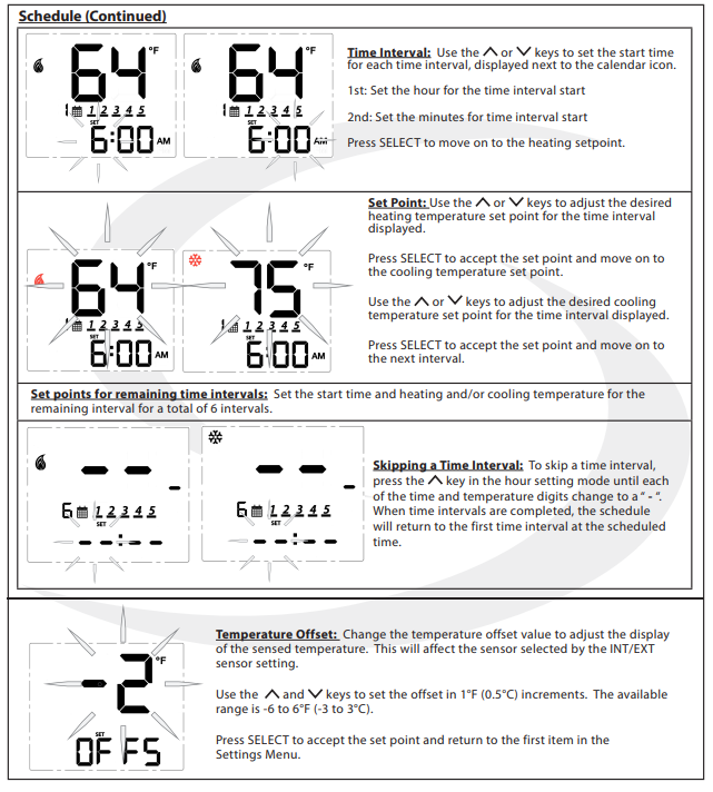
| P10 | Offset of internal sensor | ±6°F – 1°F increments(±3°C – 0 .5°C increments) | 0°F (0°C) |
| P | Name | Values | Default | Description/Comment | |
| P11 | Offset of external sensor | ±6°F – 1°F increments(±3°C – 0 .5°C increments | 0°F (0°C) | ||
| P12 | External sensor | 0 = External sensor | 0 | Standalone mode: P12 = 0 | |
| Set to EXT with key | |||||
| 1 = Zigbee remote sensor | |||||
|
P13 |
Pipe sensor |
0 = Analog input |
0 |
Displayed only if P01=0 and P02=3 or 4 (2-pipe with sea- sonal changeover or auxiliaryheat), which requires the pipe sensor (sold separately) to be connected . | |
| 1 = Normally open, default mode is Heat | |||||
| 2 = Normally open, default mode is Cool | |||||
| 3 = Normally closed, default mode is Heat | |||||
| 4 = Normally closed, default mode is Cool | |||||
| P14 | Pipe sensor threshold for cooling | 50 to 77°F increment 1°F(10 to 25°C increment 0 .5°C) | 50°F (10°C) | ||
| P15 | Pipe sensor threshold for heating | 81 to 95°F increment 1°F(27 to 35°C increment 0 .5°C) | 86°F (30°C) | ||
| P16 | Setback input | 0 = Disable | 0 | ||
| 1 = Normally closed | |||||
| 2 = Normally open | |||||
| P17 | Setback heating setpoint | 50 to 68°F increment 1°F (10 to 20°C increment 0 .5°C) | 15°C (59°F) | Display only if P16=1/2 | |
| P18 | Setback cooling setpoint | 23 to 32°C increment 0 .5°C (73 to 90°F increment 1°F) | 86°F (30°C) | Display only if P16=1/2 | |
| P19 | Setback Unoccupied to Occupied delay | 1 to 3 seconds | 1 sec | Display only if P16=1/2 | |
| P20 | Setback Unoccupied to Occupied delay | 2 to 30 minutes | 2 mins | Display only if P16=1/2 | |
| P21 | Setback mode or Off mode when unoccu- pied | 0 = Setback mode | 1 | Display only if P16=1/2 | |
| 1 = Off mode | |||||
|
P22 |
Accessory function |
0 = No function |
0 |
Normally Open |
|
| 1 = Humidifier | |||||
| 2 = Dehumidifier | |||||
| 3 = ERV/HRV | |||||
| P23 | TPI or Span | 0 = TPI | 1 | ||
| 1 = Span control | |||||
| P24 | Modulation Response Time | 0 = Slow response time | 1 | Display only if P23=0 | |
| 1= Fast response time | |||||
| P25 | TPI heat control CPH | 3 ~ 12 on/off cycle per hour | 6 | Display only if P23=0 | |
| P26 | TPI cool control CPH | 3 ~ 12 on/off cycle per hour | 3 | Display only if P23=0 | |
| P27 | CPH for Auxiliary Electrical Heater | 3 ~ 12 on/off cycle per hour | 6 | Display only if P23=0 | |
| P28 | Set span for heating using span control | .5° to 2°F increment 0 .5°F
(0 .25° to 1°C increment 0 .25°) |
0 .5°F
(0 .25°C) |
Display only if P23=1, deviceonly display 0 .2/0 .5/0 .7/1 .0°C or 0 .5/1 .0/1 .5/2 .0°F |
| P | Name | Values | Default | Description/Comment |
| P29 | Set span for cooling using span control | 0 .5° to 2°F increment 0 .5°F(0 .25° to 1°C increment 0 .25°) | 0 .5°F(0 .25°C) | Display only if P23=1, deviceonly display 0 .2/0 .5/0 .7/1 .0°C or 0 .5/1 .0/1 .5/2 .0°F |
| P30 | Minimum turn off time for heating | 10 to 300 seconds | 10 | Display if P02<>1 |
| P31 | Minimum turn off time for cooling | 10 to 300 seconds | 10 | Display if P02<>0 |
| P32 | Call start delay | From 0 to 15 minutes | 0 | Delay after determining Call forHeat/Cool before valve is opened . |
| P33 | Fan turn on delay | 0 to 600 seconds | 0 | Delay to allow coils to reach oper- ating temp |
| P34 | Fan turn off delay | 0 to 180 seconds | 0 | Delay to circulate residual heat/ cool . |
| P35 | Delay to switch to On Call Fan after initialHeat/Cool is satisfied . | 0=2 hours | 0 | |
| 1=4 hours | ||||
| P36 | Key lock timing | 0 = Manual | 0 | Note: In Auto mode, keys will
lock after 5 minutes of keypad inactivity . |
| 1 = Auto (lock keys after 5 minutes) | ||||
| 2 = Unlock | ||||
| P37 | Enable/Disable User Unlock in Simplemode and Local mode | 0 = user can unlock by ^ and v | 0 | In Standalone Mode, user canunlock by ^ and v regardless P37 setting |
| 1 = user cannot unlock by ^ and v | ||||
| P38 | Service filter | OFF | OFF | 1 to 99 x 100 operating hrs (e .g . 99= 9,900 oper . hrs) |
| 1 to 99 (99 means 9900hrs = 99*100) | ||||
| P39 | Status after power outage | 0 = Off mode | 1 | Thermostat will turn Off or be restored to Last configuration. |
| 1 = Last configuration | ||||
| P40 | DSTDaylight saving time | 0: Disable | 1 | Used for local mode and stand- alone mode |
| 1: Enable | ||||
| P41 | Purge Function | 0: Disable | 1 | P01 = 0 (2-Pipe) only |
| 1: Enable | ||||
| P42 | Purge Time | 1-7 | 3 | Minutes to purge |
| P43 | Purge Wait | 6-36 | 24 | Hours of inactivity before purge |
|
P44 |
Key lock type |
1: Lock HVAC only |
7 |
HVAC = Mode and set point Fan = fan button
Settings = Settings button
Combination key pressing and , or MODE, will not be locked at any time. |
| 2: Lock Fan only | ||||
| 3: Lock HVAC and Fan | ||||
| 4: Lock Settings | ||||
| 5: Lock Settings and HVAC | ||||
| 6: Lock Settings and Fan | ||||
| 7: Lock All |
REFERENCE
Download Manual
Salus ST101ZB Low Voltage Fan Coil Thermostat User Manual
Other Manual
Salus ST101ZB Low Voltage Fan Coil Thermostat Product Specification Guide
Salus ST101ZB Low Voltage Fan Coil Thermostat Installation Guide