SALUS RT520RF Wired Programmable Thermostat

Introduction
The RT520 and RT520RF are the latest additions to SALUS’ tried and tested RT range of thermostat heating controls. With a new on-board load compensation feature, they offer the most cost effective fully compliant Boiler Plus solution on the market providing the homeowner with optimum efficiency and maximum heating control comfort. Available in both wired and wireless RF versions, the new RT520 series include all the features of the previous RT series with a larger more intuitive LCD display and a handy new suite of additional operational and efficiency functions.
Before use please read this manual carefully.
Product Compliance
This product complies with the essential requirements and other relevant provisions of the following EU Directives: EMC 2014/30/EU, LVD 2014/35/EU, RED 2014/53/EU and RoHS 2011/65/EU. Full text of the EU Declaration of Conformity is available on www.saluslegal.com
868.0-868.6MHz; <13dBm
Safety Information
Use in accordance to national and EU regulations. Use the device as intended, keeping it in dry condition. Product for indoor use only. Installation must be carried out by a qualified person in accordance to national and EU regulations.
Always ensure the AC mains power is switched off before installing or working on any components (this includes replacing the batteries). Use only AA 1.5 V alkaline batteries in the thermostat. Place the batteries into the battery slot located in the back of the thermostat. Do not use rechargeable batteries.
Technical Specification
| RT520 Thermostat | RT520TX Thermo- stat (transmitter) | |
| Thermostat supply | 2 x AA alkaline batteries | 2xAAalkalinebatteries |
| Thermostat rating max | 3 (1) A | – |
| OpenTherm terminals | A / B | – |
| Outputs | Voltage free
NC / NO / COM terminals |
– |
| Temperature range | 5°C – 33.5°C | 5°C – 33.5°C |
| Temperature accuracy | 0.1°C OR 0.5°C | 0.1°C OR 0.5°C |
| ErP control class | V | V |
| Radio frequency | – | 868 MHz |
| Dimension [mm] | 118 x 95 x 26 [mm] | 118 x 95 x 26 [mm] |
| RXRT520 Receiver | |
| Receiver supply | 230 V AC |
| Receiver rating max | 16 (5) A |
| OpenTherm terminals | A / B |
| Outputs | Voltage free NO / COM terminals |
| Radio frequency | 868 MHz |
| Dimension [mm] | 96 x 96 x 26 [mm] |
Button Functions
- MENU – enter the menu options, press and hold for 3 sec to return to main screen or to deactivate Boost Mode.
- SELECT – confirm changes and enter menus.
- DOWN – decrease the temperature and move through the menus.
- UP – increase the temperature and move through menus.
- BOOST – activate Boost Mode.
- MANUAL – activate / deactivate Manual Mode.
- ON – When in Manual Mode, ON will turn the boiler on.
- OFF – When in Manual Mode, OFF will turn the boiler off.
- AUTO – Receiver operates in automatic mode according to the thermostat.
- MANUAL – Receiver output is controlled by the On/Off slide switch.
LCD Icon Description

- Text Bar
- Temperature Unit
- Day of the week (numeric)
- Day of the week (alphabetic)
- Clock
- AM / PM
- Cooling Mode On
- Holiday Mode On
- Manual Mode On
- Heating Mode On
- Low battery status
- Wireless connection with the receiver
- Service Mode On
- Temperature measured / set
- Program number
- Settings
- Program indicator
- Boost function
RT520 Thermostat Terminals Description
| Terminal | Description |
| B / A | OpenTherm Communication Wire |
| NC | Switched Live OFF |
| NO | Switched Live ON |
| COM | Common Terminal |

RXRT520 Receiver Terminals Description
| Terminal | Description |
| B / A | OpenTherm Communication Wire |
| NO | Switch Terminal |
| COM | Common Switch Terminal |
| L; N | Supply (230 V AC) |

RT520 Wiring Diagram
RT520TX Wiring Diagram
OpenTherm Power Up and Configuration
Please make the receiver connections and power the receiver before inserting the batteries into the thermostat.


TPI (Time Proportional & Integral) is a self-learning, time-proportional control algorithm. TPI type control ensures economical operation of the system thanks to more precise temperature maintenance during the control process. In addition to an accurate and stable room temperature, the advantage of this system is the minimization of energy consumption and significant savings. RT520 offers 3 types of TPI controls:
- for radiators (6CPH);
- for underfloor heating (3CPH);
- for electric heating (9CPH).
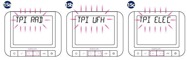
- Using UP or DOWN, select the TPI algorithm you want to use for heating control. Press OK to confirm.
Hysteresis is the temperature difference between which the thermostat works, keeping the set temperature. For example, if you set the temperature to 20°C and if the hysteresis is ± 0.5°C, the heating will be turned on when the room temperature drops to 19.5°C and turned off when the temperature reaches 20.5°C.

When the OPTIMUM START function is active, the thermostat sends a heating signal to the heat source beforehand so that the preset temperature in the room is reached at the set time in the schedule.
When the OPTIMUM STOP function is active, the thermostat, taking into account the inertia of the system, switches off the heat source earlier, keeping the temperature set in the schedule.
Exemplary operation of the thermostat according to the schedule 6:00 – 23:00 21°C & 23:00 – 6:00 19°C:
- A – OPTIMUM START ON (earlier it turns on the heating – it goes towards the set 21°C)
- B – OPTIMUM START OFF (turns on heating according to a schedule)
- C – OPTIMUM STOP ON (earlier it turns off the heating – it goes to the set 19°C)
- D – OPTIMUM STOP OFF (turns off heating according to a schedule)

Switching between manual mode and automatic mode
TO SWITCH FROM AUTOMATIC TO MANUAL MODE:

TO SWITCH FROM MANUAL TO AUTOMATIC MODE:

Programming
Automatic Mode
The schedule has 6 time intervals for which different temperatures can be adjusted. You can set 2, 3 or up to 6 temperatures per day. You must define all time periods. Here is an example of setting a certain time with a certain temperature.

Note: Repeat the process for all time periods.
If you only need to change the set temperature twice a day, below is how to cancel one or more intervals.
| TIME: | 6 TEMP/DAY | 2 TEMP/DAY |
| 06.00 | 21 °C | 21 °C |
| 10.00 | 14 °C | – |
| 12.00 | 21 °C | – |
| 14.00 | 14 °C | – |
| 18.00 | 21 °C | – |
| 21.00 | 14 °C | 14 °C |
Here are some examples of weekly schedules (for 6 and 2 temperature changes during the day).
Landlord Settings
Administrator settings is a function protected by a PIN code that allows the administrator to set a service reminder on the regulator that will warn the tenant about the upcoming boiler inspection.


RT520TX Thermostat Pairing with the Receiver
If you are using the RT520RF pack, the pairing between the thermostat and the receiver is already done. During the pairing process, please make sure the thermostat and the receiver are at least 1 meter from each other.
If you bought the RT520TX and RXRT520 separately or if you want to re-pair thermostat with the receiver, make sure that the device is disconnected from the power supply and the switches on the receiver have been set to AUTO and ON. Then connect the receiver to the power supply and wait for the red LED to light steadily. Then switch to the OFF position and again to ON position quickly. The red flashing LED will confirm entering the pairing mode.

Test the Pairing Process
Factory Reset
Note: Landlord settings will not be reset. Devices are still paired together.
Reference
Download Manual
SALUS RT520RF Wired Programmable Thermostat Quick Guide
OTHER MANUALS
SALUS RT520RF Wired Programmable Thermostat User Manual
SALUS RT520RF Wired Programmable Thermostat Wiring Diagram