
Robertshaw RS5110 Programmable Thermostat

Thank you for purchasing a Robertshaw RS5000 Series programmable thermostat. This user’s manual will guide you through the setup of the RS5110 single-stage and the RS5220 two-stage thermostats. The thermostat should already be mounted and correctly wired. The default settings will enable the thermostat to operate efficiently. Before making any changes to the schedule read the section on Default Settings.
Features
- Pop-Up Wizard
- Automatic changeover
- Circulating fan
- Worry-Free memory retention
- Easy change battery
- Large backlit display
- Filter change reminder
- Low battery indicator
- Fahrenheit and Celsius displays
- EnergyStar™ compliant
- Dual power
- Adjustable 1st stage temperature differential: 0.5 F degrees to 3.0 F degrees (0.5 C degrees to 1.5 C degrees)
- Accuracy within ±1 F degree
- Universal staging on multi-stage units
- Automatic heating shutdown if temperature exceeds 99°F (37°C)
- Keypad security lockout
- 4 events per day for heating and cooling
- 5-2 day schedule
- User settable Hi and Lo temperature limits
- Vacation setpoint override
Application
The Robertshaw 5000 family of thermostats is designed to control gas, electric, oil, heat pump, and millivolt heating and electric cooling systems. The RS5110 is a single-stage thermostat while the RS5220 is a two-stage thermostat. The RS5000 thermostats use 5-2 programming. This means the 5 weekdays will operate on one schedule and the 2 weekend days will operate on a second schedule.
IMPORTANT SAFETY INFORMATION WARNING
- Always turn off power at the main fuse or circuit breaker panel before installing, removing, cleaning, or servicing the thermostat.
- Read all the information in this manual before installing this thermostat.
- This is a 24V AC low-voltage thermostat. Do not install on voltages higher than 30V AC.
- All wiring must conform to local and national building and electrical codes and ordinances.
- Do not short (jumper) across terminals on the gas valve or at the system control to test installation. This will damage the thermostat and void the warranty.
- Do not connect the ground to any terminal in this unit.
- This thermostat is configured with automatic compressor protection to prevent damage because of short cycling or extended power outages. Short cycle protection provides a delay between heating and cooling cycles on heat pumps.
Detailed mounting and wiring instructions are explained in the Installation Manual Refer to the Pop-Up Wizard section in the Installation Manual for a complete list of factory defaults and contractor settings.
Providing Power to the Thermostat
For wiring diagrams refer to the Installation Manual. The thermostats will operate using 24V AC or two AA batteries. When the two AA batteries are installed the thermostat will continue to run if the 24V AC fails.
Installing or Changing the Batteries
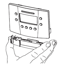
To remove the battery compartment gently squeeze the ribbed edges on both sides. The battery compartment will pull down from the thermostat body and will detach. Install two AA batteries following the polarity as shown inside the compartment. Place the compartment back into the thermostat. When the batteries are low the thermostat will enter a low battery mode. Low battery mode has two levels.
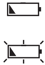
- LEVEL 1: The low battery icon will be displayed. The thermostat will continue to operate. Replace the batteries as soon as possible
LEVEL 2: The low battery icon will flash. If 24V AC is present the thermostat will continue to operate if the batteries are discharged or removed. If 24V - AC is not present the thermostat runs on batteries only and THE SYSTEM WILL NOT OPERATE. Replace batteries immediately.
The clock will continue to run for 10 minutes when the batteries are removed. Replace batteries if leaving the thermostat unattended for more than 30 days.
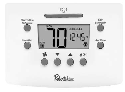
Display Map
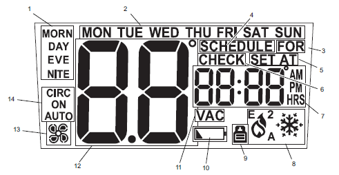
The thermostat display will show information that is being used during operation or programming. This illustration shows all of the display’s possibilities with an explanation.
- Event names (used for editing schedule).
- The day is displayed on the IDLE screen. Also used to display day ranges when editing the schedule (e.g., SAT-SUN for the weekend).
- Used with the clock to display hold duration (e.g., FOR 2h).
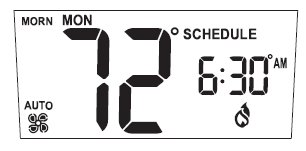
- Displayed when running a schedule.
- Used with a setpoint.
- Used along with clock for service reminders (e.g., CHECK HP).
- Used for time, current setpoint, and some configuration data (e.g., filter hours).
- HVAC mode and status. Icons blink when active. A is for Auto, 2 is for the second stage, E is for an emergency
 , is for heating, and is for
 cooling.
 - Indicates when security is active.
- Low battery indicator.
- Displayed when on a vacation hold.
- Used for ambient temperature and configuration data (e.g., first stage differential, F or C, etc.).
- Fan status (rotates when active).
- Fan use (selected by pressing the FAN button).
Set Time and Day
To adjust the time and day settings press the SET TIME button. The hour will flash. If a button is not pushed within 10 seconds the thermostat returns to operation. To change the settings:
- Use the
 buttons
 to change the flashing number.
 - Press the SET TIME button to move through hours, minutes, and days of the week.
- Make changes as needed. They will be saved automatically.
NOTE: THE THERMOSTAT WILL NOT CORRECT FOR DAYLIGHT SAVING TIME.
The thermostat will now function properly using the default schedule.
Default Settings
This thermostat is preprogrammed with a schedule that is recommended by EnergyStar™. The schedule is designed to lower energy costs year-round.The default schedule settings are:
| Time | Cooling °F | Heating °F | |
| Morn | 6:00 am | 78 | 70 |
| Day | 8:00 am | 85 | 62 |
| Eve | 6:00 pm | 78 | 70 |
| Nite | 10:00 pm | 82 | 62 |
User Programmable Settings (Default)
During any program changes the display returns back to the operating display if a button has not been pushed within 10 seconds.
The temperature scale is set to Fahrenheit.
- The night light is off.
- The first stage differential is 1F degree.
- The second stage differential (RS5220) is 2F degrees.
- The auto changeover deadband is 3F degrees.
- The filter reminder length is off.
- The temperature offset is 0 degrees.
- The HI heat limit is 90°F (32°C).
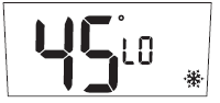
- The LO cool limit is 45°F (7°C)
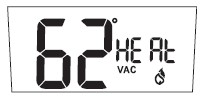
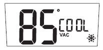
- The vacation temperature settings are set at heating 62°F, and cooling at 85°F.
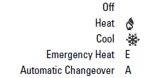
- The operation mode will be one of the following:
- The fan setting is Auto.
- The fan setting is Auto.
The keypad has no password protection. Refer to the Pop-Up Wizard section in the Installation Manual for a complete list of factory defaults and contractor settings.
Emergency Heat
Your system may include Emergency Heat. The RS5220 thermostats have an emergency heat capability for multi-stage heat pump systems. To determine if your system is capable of using emergency heat contact your contractor. Use the![]() button to enter the EMER mode. An E will be displayed with the Heat symbol. This mode is used to bypass the heat pump when it needs servicing or when it cannot keep up with the heat demand.
button to enter the EMER mode. An E will be displayed with the Heat symbol. This mode is used to bypass the heat pump when it needs servicing or when it cannot keep up with the heat demand.
Auto Changeover
Auto changeover is the ability of the thermostat to switch automatically between heating settings and cooling settings. This is useful in spring and fall when the days are warm and the nights are cool. In heat mode, if the room continues to warm beyond a set threshold the thermostat switches to the cool mode and the associated cooling settings. The reverse is also true. As the room temperature changes, the thermostat will call for heating or cooling as needed. To prevent the heating and cooling systems from overriding each other, an automatic changeover deadband is used. The deadband is the number of degrees that the room temperature can move away from the active setpoint until heating or cooling is called for. The larger the deadband the more the room temperature will vary.
Making Changes to the Programmed Settings
Any setting can be changed when it is flashing by pushing![]() or
or![]() If a button is not pushed within 10 seconds the thermostat returns to operation. The following buttons can be accessed from the front panel
If a button is not pushed within 10 seconds the thermostat returns to operation. The following buttons can be accessed from the front panel
 START/STOP SCHEDULE: Switches between running a schedule and manual (permanent override). Cancels a temporary or vacation override.
EDIT SCHEDULE: Use this button to start editing the schedule. Push repeatedly to move through the selections.
VACATION: Used to set a temporary setpoint for a number of days.
SET TIME: Sequences through the hour, minute, and day.
LIGHT BAR: Turns on the display backlight for 10 seconds.
FAN: Turns fan to AUTOMATIC, CIRCULATE, or ON.
UP ARROW: Used during programming to increase the flashing item.
DOWN ARROW: Used during programming to decrease the flashing item.
HEAT/COOL: Sequences through OFF, HEATING, COOLING, and AUTO. If you are using an RS5220 and it is configured as HP, emergency heat is also displayed.
To Make Changes in the Schedule:
This thermostat can operate using a single setpoint by overriding the schedules. If you will be using this thermostat for single setpoint operation skip to Overriding the Schedule. Use the following table to document your schedule settings before editing the schedule on the thermostat.
| Time | Cool | Heat | |
| Morning | |||
| Day | |||
| Evening | |||
| Nite |
Press START/STOP SCHEDULE at any time to exit and save your settings. Push the EDIT SCHEDULE. The start time of the setpoint will be flashing. If a button is not pushed within 30 seconds the thermostat returns to operation. Use the or to change the hour of the start time if desired. Push the EDIT SCHEDULE to move to minutes. Use the or to change the temperature setpoint. Pressing ![]() will switch between cooling and heating. Use and change the setpoint.
will switch between cooling and heating. Use and change the setpoint.
– OR –
Push EDIT SCHEDULE to move from heat to cool or cool to the heat temperature setting. Use the or to change the temperature setpoint.
NOTE: THE HEATING AND COOLING SETPOINTS CANNOT BE ENTERED AS CROSSED. THAT IS, THE COOLING SETPOINT CANNOT BE LOWER THAN THE HEATING SETPOINT.
Push the EDIT SCHEDULE and repeat this process for the remaining three-weekday settings. All of the weekdays will use this schedule. After the weekday schedule is complete the display will show the weekend schedule. Continue the same steps to program the four-weekend settings. When you are finished, the thermostat will be in operation after 30 seconds
To Make Changes to the Settings
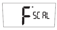
When and are pressed at the same time the thermostat will display the current settings in order. To change any setting: When the setting is visible and flashing press the or arrows to adjust the number on the screen. To exit the changes and save: press START/STOP SCHEDULE. The thermostat will return to operation.
SCAL = Scale in °F (Fahrenheit) or °C (Celsius)
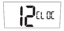
CLOCK = Clock setting in 12 or 24-hour readings
light =
Display backlight always on ”Y” or of”n”. Also called the nightlight feature. If the thermostat has been wired to enable this feature it will be displayed and the setting can be changed.

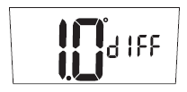
DIFF = The differential keeps the thermostat from turning on for small changes in temperature. When in Fahrenheit the range is 0.5 to 3.0 degrees. In Celsius, the range is 0.5 to 1.5 degrees. The differential is factory set to 1.0 F degree (0.5 C degree). This means that whenever the room temperature is more than 1 F degree (0.5 C degree) different from the set temperature the system will turn on. If the system is turning on too often, increase the differential setting. Note that a larger differential will mean the room temperature changes more before the system turns on.
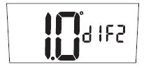
DIF2 = SECOND STAGE DIFFERENTIAL = Operates with the first stage to control a second heating/cooling system. This number will be added to the first stage differential (See: Two Stage Systems). If the first stage is running too often lower the settings. This will turn the second stage on to help the first stage. If both stages are turning on too often, increase this setting to delay the second stage.
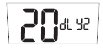
DLY2 = SECOND STAGE DELAY = This timer starts when the first stage turns on. It resets when the first stage turns off. If this timer expires, the second stage will turn on (See Two Stage Systems).
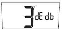
DEDB = Deadband for auto changeover = the number of degrees that the room temperature can move away from the active setpoint until heating or cooling is called for. The larger the deadband the more the room temperature will vary. This can be from heat to cool or cool to heat
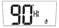
HI = High Heat Limit = This is the highest allowed heating setpoint. The user will not be allowed to set a scheduled setpoint or override a temperature higher than this value.
LO = Low Cool Limit = This is the lowest allowed cooling setpoint. The user will not be allowed to set a scheduled setpoint or override a temperature lower than this value.
VAC HEAT = Vacation Heat Setpoint = This is the temperature setpoint for the heating system when a vacation override has been made active.
VAC COOL = Vacation Cool Setpoint = This is the temperature setpoint for the cooling system when a vacation override has been made active.
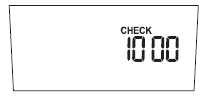
CHECK = Timer to remind the homeowner to maintain the filter. The default setting is off. The timer runs when the system is on and can be set at 0 (OFF) or up to 9900 hours. When the timer expires, CHECK FLTR is displayed. Press any button to reset and return to the normal display
CYCL = Cycle Timer allows a compressor to rest between cycles. Can be set from 0 to 5 minutes in 1-minute income
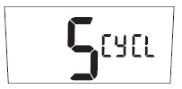
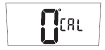
WARNING: A wrong short-cycle setting can damage your equipment. This should only be changed by a trained HVAC professional. CAL = Calibration offset. Changes the displayed temperature from the actual temperature by +3 to -3 degrees in one-degree increments. Increasing the offset by +2 will cause the thermostat to display a temperature that is 2 degrees higher than the actual room temperature
Security Lockout to Protect the Settings
The buttons on the front of the thermostat can be locked with a password.
To create a password:
- Press the buttons
 at the same time and hold them in for 5 seconds. You will be asked for a 4-digit password.
 - Each digit is set using the and buttons. Press the to move to the next digit. Press
 to move back.
 - The password is saved after 10 seconds or by pressing andat the same time.
All of the front buttons are now locked out until the password is entered. Pressing any button will cause ![]() it to flash.
it to flash.
To unlock the buttons:
- Push and hold the buttons for 5 seconds until the request for a password is displayed.
- Enter the digits for the password by pressing the and buttons. Press the to move to the next digit. Press to move back.If the wrong password is entered the display will flash NO for 5 seconds then return to normal.
- Press and when the correct password is displayed. The buttons will be unlocked. Once the security has been disabled, a password needs to be recreated to protect the settings.
Two Stage Systems
A 2nd stage is a second or additional system that will provide extra heating or cooling. When a 2nd stage is operating the display will show the number 2 by the heating and cooling icons.
A programmable temperature differential (default value is 2.0 F degrees or 1.0 C degrees) and time delay (default value 20 minutes) control the 2nd stage cycle.
The 2nd stage turns on when:
- The room temperature changes from the setpoint by the sum of the 1st and 2nd stage differential settings.
- The first stage has been on for the specified delay time, but the heating/cooling demand has not yet been met.
Energy Efficient Recovery™
With Energy Efficient Recovery, the thermostat looks ahead to the next event and attempts to reach the next setpoint at the exact time of the event. If you have two stages, the thermostat will use only the first stage during this period. This is more efficient than waiting until the next event and then turning on both the first and second stages.
Backlit Display
This thermostat is equipped with a backlight to make viewing the display easy. Press the ![]() button to activate the backlight. The backlight will turn off after 10 seconds of inactivity. If the thermostat is wired to have the backlight stay on all the time the night light can be turned on/off in the settings menu.
button to activate the backlight. The backlight will turn off after 10 seconds of inactivity. If the thermostat is wired to have the backlight stay on all the time the night light can be turned on/off in the settings menu.
Overriding the Schedule
When the thermostat has been programmed, the settings and the schedule are saved. The thermostat will follow the schedule unless an override is entered.
Three methods of override are available.
Permanent Override
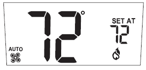
Press START/STOP SCHEDULE until the word SCHEDULE is not shown on the display. The setpoint temperature is displayed. The thermostat will call for heat or cooling to maintain the setpoint temperature. Press or to change the setpoint. The heat or cool mode should be selected.
Schedule Overrides
When the thermostat is following a schedule, an override allows the thermostat to function with a single setpoint for a time period. A temporary override is entered as a setpoint for a number of hours. A vacation override is entered as a setpoint that is held for a number of days.
Temporary Override
- Press or to display the flashing setpoint and the number of hours.
- Use and to change the setpoint.
- Press SET TIME to move to the hours.
- Use and to set the length of the override.
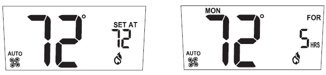
After 5 seconds the thermostat will start the operation of the override. The display will show room temperature, and the setpoint will alternate with the number of hours remaining in the override. The schedule will resume after the programmed override time expires. Heat or cool must be selected. Cancel the override by pressing START/STOP SCHEDULE.
Vacation Override
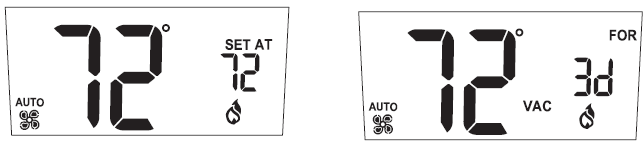
This override is programmed by pressing VACATION. The number of days will flash. Use and to change the number of days. After 5 seconds the thermostat will begin the operation of the vacation override. The display will show room temperature and the setpoint will alternate with the number of days remaining in the override. Use and to change the setpoint. This will become the new setpoint for future vacation overrides. Cancel the override by pressing START/STOP SCHEDULE.
Origin of Setpoint
When the thermostat is using a schedule the temperature setpoint originates from the schedule settings.
When one of the schedule overrides is active the setpoint originates from the override temperature. Use the display to determine the origin of the current temperature setpoint. Permanent Override – The day, time, and schedule are not displayed.
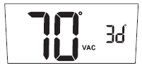
Vacation Override – Vac and For are displayed. The clock shows days of override. The display alternates days of override with a setpoint.
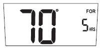
Temporary Override – The day and For are displayed. The clock shows hours of override. The display alternates hours of override with a setpoint.
Automatic Shut-Down
The thermostat will not display if the temperature is higher than 99°F (37°C) or lower than 32°F (0°C). If this happens, the display will show HI or LO. The thermostat continues to control heating and cooling and will display the room temperature when it is between 32°F (0°C) and 99°F (37°C).
Setting the Fan to ON, AUTO, or CIRC
The fan has 3 settings: On, Auto, and Circ. Press the ![]() button to switch between the three.
button to switch between the three.
ON: The fan is on constantly. The room temperature, set points, and status of the heating and cooling equipment have no effect on the fan.
AUTO: When there is a call for heating or cooling the fan will turn on.
CIRC: The fan operates in a cycle of on for 10 minutes and off for 20 minutes. When there is a call for heating or cooling the cycle stops and the fan responds to the call. The fan circulation cycle resumes when the call for heating or cooling is satisfied.
Troubleshooting
| Problem | Action |
| The thermostat does not turn on system. | Check wiring (see Wiring Diagrams
section in the Installation Manual). |
| The system turns on too often. | Increase temperature differential (see To Make Changes to the Settings section). |
| The system fan does not operate properly. | Move fan option switch to either gas or electric, to match system (see Setting the Fan to ON, AUTO, or CIRC section). |
| The thermostat does not display proper room temperature. | Check F/C (Fahrenheit/Celsius) setting. (see To Make Changes to the Settings section. |
| The display shows HI or LO and room temperature is normal. | Call a licensed service person to replace/repair. |
If problems with the thermostat cannot be resolved, contact: www.invensyscontrols.com or Technical Support: at (800) 445-8299
Five-Year Limited Warranty
Invensys Controls warrants to the original contractor installer, or to the original consumer user, each new Robertshaw thermostat to be free from defects in materials and workmanship under normal use and service for a period of five (5) years from the date of purchase. This warranty and our liability do not apply to batteries or merchandise that has been damaged by misuse, neglect, mishandling, alterations, improper installation, or use in a way other than in accordance with Invensys Controls’ recommendations and instructions. Invensys Controls agrees to repair or replace at its option any thermostat under warranty provided it is returned within the warranty period, postage prepaid, with proof of the date of purchase. The cost of thermostat removal or reinstallation is not the responsibility of Invensys Controls. Repair or replacement as provided under this warranty is the exclusive remedy of the consumer. Invensys Controls shall not be liable for any incidental or consequential damages for breach of any express or implied warranty on this product, or under any other theory of liability. Except to the extent prohibited by applicable law, any implied warranty of merchantability or fitness for a particular purpose on this product is limited to the duration of this warranty.
Some states do not allow the exclusion or limitation of incidental or consequential damages, or allow limitations on how long an implied warranty lasts, so the above limitations or exclusions may not apply to you. This warranty gives you specific legal rights, and you may also have other rights which vary from state to state.
For warranty returns, send thermostat, shipping prepaid to: Invensys Controls
Warranty Claims Department515 S. Promenade Corona, CA 91719
In Canada: Invensys Controls 3505 Laird Road Unit #14 Mississauga, Ontario L5L 5Y7 Canada
Attn: Warranty Department 515 South Promenade Avenue Corona, CA 92879-1736
United States of America www.invensyscontrols.com
©2007 Invensys Controls 8/07
Reference
Download Manual:
Robertshaw RS5110 Programmable Thermostat User Manual
Other Manual:
Robertshaw RS5110 2-Day Programmable Thermostat Product Specifications Guide
![]()
Leave a Reply