
Pro1 T955WH Non-Programable Thermostats

Installation
Pro1 Technologies
P.O. Box 3377
Springfield, MO 65808-3377
Toll Free: 888-776-1427
Web: www.pro1iaq.com
Hours of Operation: M-F 9AM – 6PM Eastern
Thermostat Application Guide
| Description | |
| Gas or Oil Heat | Yes |
| Electric Furnace | Yes |
| Heat Pump (No Aux. or Emergency Heat) | Yes |
| Heat Pump (With Aux. or Emergency Heat) | Yes |
| Multi-Stage Systems | Yes |
| Heat Only Systems | Yes |
| Cool Only Systems | Yes |
| Millivolt | No |
| Humidity | Yes |
| Dual Fuel | Yes |
Power Type
- Battery Power*
- Hardwire (Common Wire)
- Hardwire (Common Wire) with
- Battery Backup
A trained, experienced technician must install this product.
Carefully read these instructions. You could damage this product or cause a hazardous condition if you fail to follow these instructions. Una version en español de este manual se puede descargar en la pagina web de la compañia.
Note: If you are using remote sensors the thermostat must be hardwired.
Wireless Type Selection
The thermostat and base module contain selectable wireless communication options. Each component has a jumper switch label FSK and ASK. Default setting: FSK.
- All components must be set to the same position for wireless communication.
- Both modes utilize a 916 MHz frequency.
- FSK: frequency-shift keying, is the recommended mode.
- ASK: amplitude-shift keying, should be selected when using components that can not communicate with FSK.
The images below illustrate the location of jumper switches for each item that has one. Note only the thermostat and Base Module are included in this package.
The table below lists the mode options for T955WH wireless thermostat and its accessories.
| Component | Mode Options |
| T955WH Thermostat | FSK or ASK |
| T955WH Thermostat Base Module | FSK or ASK |
| RZ251W – Indoor Remote* | FSK or ASK |
| RZ250W – Outdoor Remote* | FSK or ASK |
| R251W – Indoor Remote | ASK |
| R250W – Outdoor Remote | ASK |
| W150W – Wireless Repeater | ASK |
Installation Tips
Wall Locations
The thermostat should be installed approximately 4 to 5 feet above the floor. Select an area with average temperature and good air circulation.
Do not install thermostat in these locations:
- Close to hot or cold air ducts
- That are in direct sunlight
- With an outside wall behind the thermostat
- In areas that do not require conditioning
- Where there are dead spots or drafts (in corners or behind doors)
- Where there might be concealed chimneys or pipes
Installation Tip
Pick an installation location that is easy for the user to access. The temperature of the location should be representative of the building.
Thermostat Subbase Installation
- Horizontal Mount: For horizontal mount put one screw on the left and one screw on the right.
- Vertical Mount: For vertical mount put one screw on the top and one screw on the bottom.
Installation Tip: Electrical Hazard
Failure to disconnect the power before beginning to install this product can cause electrical shock or equipment damage.
Mercury Notice
All of our products are mercury free. However, if the product you are replacing contains mercury, dispose of it properly. Your local waste management authority can give you instructions on recycling and proper disposal.
Base Module Subbase installation
- Horizontal Mount: For horizontal mount put one screw on the left and one screw on the right.
- Vertical Mount: For vertical mount put one screw on the top and one screw on the bottom.
Wiring Note Wire the base module’s subbase the same way you would wire a hardwired thermostat subase.
Note: To connect the base module to the master thermostat, refer to the directions on page 13 of this manual.
The base module must be hardwired (C and R terminals connected to 24V power.)
Mount Thermostat and Base Module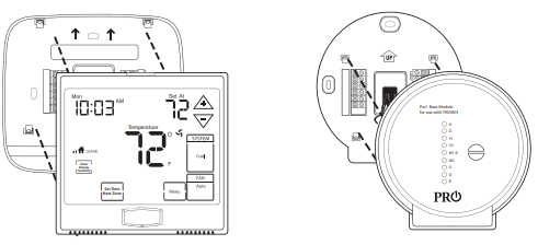
Align the 4 tabs on the subbase with corresponding slots on the back of the thermostat/base module, then push gently until it snaps in place.
Note: To ensure a solid fit between the thermostat/base module and the subbase:
- Mount subbase to a flat wall
- Use screws provided
- Drywall anchors should be flush with the wall
- Wires should be pushed into the wall
Battery Installation
Battery installation is optional if there are no remotes connected to the Master Thermostat (C terminal con-nected). If you connect an outdoor remote and/or indoor remote sensors it is required the thermostat be hardwired.
Important: High quality alkaline batteries are recommended. Rechargeable batteries or low quality batteries do not guarantee a 1-year life span.

Getting to know your thermostat
- Indicates the current room temperature
- Time and day of the week
- Low Battery Indicator: Replace batterieswhen this indicator is shown.
- Program Menu Options: Show different options during programming.
- Period Icons – This thermostat can have 2 or 4 programmable time periods per day. Icons are displayed for 4 time periods. Occupied and unoccupied will display in the text field for 2 time periods.
- REMOTE indicates a remote has control of the system.
- HOLD is displayed when thermostat program is permanently overriden.
- Setpoint: Displays the user selectable setpoint temperature
- System Operation Indicators: The COOL, HEAT or FAN icon will display when the COOL, HEAT or FAN is on. NOTE: The compressor delay feature is active if these icons are flashing. The compressor will not turn on until the 5 minute delay has elapsed.
- Humidity: Shows the humidity target setpoint settings and keys.
- Clean Display: Pressing CLEAN DISPLAY will allow 30 seconds to clean the display. The keys will be inoperable during this time. CLEAN will appear if your contractor has programmed a filter change reminder. Press CLEAN when filter has been replaced to reset the filter change reminder timer.
- Next Zone: This button will appear if optional indoor remotes are present. By selecting NEXT ZONE you can cycle through each of the zones set up during the initial installation.
- System Information: Shows which zone or zones are controlling your system. Shown only when one or more indoor sensors are connected.

- LCD Display
- Glow in the dark light button
- Fan key
- System key
- Setpoint keys
- Menu key
- Scheduled time period Icons
Important The low battery indicator is displayed when the AA battery power is low. If the user fails to replace the battery within 21 days, the screen will only show the low battery indicator but maintain all functionality. If the user fails to replace the batteries after an additional 21 days (days 22-42 since first “low battery” display) the setpoints will change to 55˚F (Heating) and 85˚F (Cooling). If the user adjusts the setpoint away from either of these, it will hold for 4 hours then return to either 55˚F or 85˚F. After day 63 the batteries must be replaced immediately to avoid freezing or overheating because the thermostat will shut the unit off until the batteries are changed.
Installation Tips
When performing an attic installation, instead of placing the base module in the attic, locate the closet nearest to the air conditioning unit. Then mount the base module high on the wall inside the closet or on the ceiling of the closet. This location will insure the base module is below the 150°F maximum ambient temperature specification.
Do not install the base module in locations:
- That are behind a chimney
- Where temperature could exceed 150°F
- Where rain or snow or extreme hot or cold is possible
Note: This base module is NOT weatherproof.
Do not install the base module in locations:
- That are behind a chimney
- Where temperature could exceed 150°F
- Where rain or snow or extreme hot or cold is possible
Note: This base module is NOT weatherproof.
Private Label Badge
About The Badge
All of our thermostats use the same universal magnetic badge. Visit the company website to learn more about our free private label program.

Gently slide a screwdriver into the bottom edge of the badge. Gently turn the screwdriver counter clockwise. The badge is held on by a magnet in the well of the battery door. The badge should pry off easily. DO NOT USE FORCE.
Wireless Communication Tips

Follow these steps for a simple wireless communication setup.
- Locate all components in area near equipment.
- Wire base module with 8ft =pigtail and temporarily mount. If you are not able to establish communication, this will allow you to relocate the module to an area with less obstruction, without having to rewire.
- Install batteries in all devices you wish to use. Thermostat, indoor/outdoor sensors.
- Press the menu button on thermostat
Press & hold tech set up button
Configure the set up for your application
Establish communication between devices - Install thermostat in final location.
Note: You must hardwire the thermostat when using remotes.
Turn on fan from thermostat to ensure communication. Once communication is established, permanently mount module.
Troubleshooting
If there is no communication between the thermostat and base module devices that are less than 50ft. apart, utilize an 8ft. pigtail to relocate and reduce interference. If there is not communication and devices are over 50ft. apart, add a W150W – Wireless Repeater.
Reestablishing Communication
Establishing communication between master thermostat and the base module. The thermostat and base module come factory linked out of the box. If however, communication is lost, follow this easy- two step process to re-establish the communication link.
- Press and hold the base module button for 3 seconds. The Blue LED will flash when ready to receive initial signal from the thermostat.(Base module must be powered by 24V. Blue LED will be continuously on when 24V power is present.)
- Hold the light key (shown here) of the thermostat for 10 seconds, the Blue LED on the base module will stop flashing after communication has been established between base module and the thermostat.
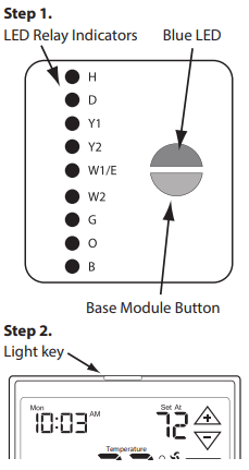 Note: The blue LED on the base module will be on when power is present. The blue LED will flash 3 times everytime it recieves a signal from the thermostat. When a relay is on the corresponding LED relay indicator will be on.
Note: If the base module does not receive a signal from the thermostat for 15 minutes it will turn off all relays until communication is reestablished. The blue LED base module will also turn off to show communication has been lost.
Note: If communication has been lost for 1 hour and if freeze protection is enabled, heat and emergency heat relays will be turned on. The heat and emergency relays will turn on for 10 minutes every hour if there has been a call for heat in the last 24 hours.
Important: DO NOT hold the light button on the thermostat for more than 10 seconds after step 2 above has been completed. Holding the light button down will break the communication link and the base module button will need to be pressed again to reestablish communication.
Wiring
Caution: Electrical Hazard
Failure to disconnect the power before beginning to install this product can cause electrical shock or equipment damage.
Warning: All components of the control system and the thermostat installation must conform to Class II circuits per the NEC Code.
- If you are replacing a thermostat, make note of the terminal connections on the thermostat that is being replaced. In some cases the wiring connections will not be color coded. For example, the green wire may not be connected to the G terminal.
- Loosen the terminal block screws. Insert wires then retighten the terminal block screws.
- Place nonflammable insulation into the wall opening to prevent drafts.
Installation Tip Do not overtighten terminal block screws, as this can damage the terminal block. A damaged terminal block can keep the thermostat from fitting on the subbase correctly or cause system operation issues.
Max Torque = 6in-lbs.
Wiring Tips
C Terminal
The C (common wire) terminal does not have to be connected when the thermostat is powered by batteries.
Wire Specifications
Use shielded or non-shielded 18-22 gauge thermostat wire.
Note:
In many heat pump systems with no emergency heat relay, a jumper can be installed between E and W2 to turn thermostat into a single stage control for Emergency Heat Operation.
- Power supply
- Factory-installed jumper. Remove only when installing on 2-transformer systems
- Use either O or B terminals for changeover valve
- If DEHUM relay requires a normally-energized input, set dehumidity relay to NC in technician setup.

- Power supply
- Factory-installed jumper. Remove only when installing on 2-transformer systems
- Use either O or B terminals for changeover valve
- If DEHUM relay requires a normally-energized input, set dehumidity relay to NC in technician setup.

Terminal Designations on the Base Module
This thermostat is shipped from the factory to operate a conventional heating and cooling system. This thermostat may also be configured for a heat pump system. See the “heat pump” configuration step on page 23 of this manual to configure the thermostat for heat pump applications.
|
Terminal |
2 Heat 2 Cool Conventional System | 2 Heat 2 Cool Heat Pump System | 3 Heat 2 Cool Heat Pump System |
| RC | Transformer power (cooling) | Transformer power (cooling) | Transformer power (cooling) |
| RH | Transformer power (heating) | Transformer power (heating) | Transformer power (heating) |
| C | Transformer common | Transformer common | Transformer common |
| B | Energized in heating | Heat pump changeover valve energized in heating | Heat pump changeover valve energized in heating |
| O | Energized in cooling | Heat pump changeover valve energized in cooling | Heat pump changeover valve energized in cooling |
| G | Fan relay | Fan relay | Fan relay |
| W/E | First stage of heat | First stage of emergency heat | First stage of emergency heat |
| Y | First stage of cool | First stage of heat & cool | First stage of heat & cool |
| Y2 | Second stage of cool | Second stage of cool | Second stage of cool & second stage of heat |
| W2 | Second stage of heat | Auxiliary heat relay, second stage of heat | Auxiliary heat relay, third stage of heat |
| H | Humidify | Humidify | Humidify |
| D | Dehumidify | Dehumidify | Dehumidify |
Terminal Designations on the Master Thermostat
|
Terminal |
2 Heat 2 Cool Conventional System | 2 Heat 2 Cool Heat Pump System | 3 Heat 2 Cool Heat Pump System |
| R | 24 VAC transformer power | 24 VAC
transformer power |
24 VAC
transformer power |
| C | transformer common | transformer common | transformer common |
Powering the Master Thermostat
If you add indoor or outdoor remote sensors to this wireless system you must hardwire the master thermostat.
- Power supply
- Factory-installed jumper. Remove only when installing on 2-transformer systems
- Use either O or B terminals for changeover valve
- If DEHUM relay requires a normally-energized input, set dehumidity relay to NC in technician setup.

Technician Setup
This thermostat has a technician setup menu for easy installer configuration. To set up the thermostat for your particular application:
- Press the MENU button.
- Press and hold the technician setup button for 3 seconds. This 3 second delay is designed so that homeowners do not accidentally access the installer settings.
- Configure the installer options as desired using the table below. Use the
 keys to change settings and the next step or previous step key to move from one step to another.
Note: Only press the DONE key when you want to exit the Technician Setup options. - Press the DONE key to exit.
| Tech Setup Steps | LCD Will Show | Adjustment Options | Default | |
|
Filter Change Reminder |
This feature will flash a reminder after the elapsed run time to remind the user to change the filter. A setting of “OFF” will disable this feature. | OFF
|
You can adjust the filter change reminder from “OFF” to 2000 hours of fan runtime in 50 hour increments. |
OFF |
|
Room Temperature Calibration |
This feature allows the installer to change the calibration of the room temperature display. For example, if the thermostat reads 70˚ and you would like it to read 72˚ then select +2. | 0
CALIbRATE |
You can adjust the room temperature display to read up to 4˚above or below the factory calibrated reading. | 0˚F |
|
Minimum Compressor On Time |
This feature allows the installer to select the minimum run time for the compressor. For
example, a setting of 4 will force the compressor to run for at least 4 minutes every time the compressor turns on, regardless of the room temperature. |
OFF | You can set the minimum compressor run time to “OFF”, “3”, “4”, or “5” minutes. If 3,4 or 5 is selected, the compressor will run for
at least the selected time before turning off. |
OFF |
Keypad Lockout Note: The selected keypad lockout functionality must be activated after exiting tech setup. If you do not perform this procedure, all keys will function freely. To lock the keypad hold down the ![]() keys for 3 seconds. You will see a lock in the display. To unlock the display hold down the
keys for 3 seconds. You will see a lock in the display. To unlock the display hold down the ![]() keys for 3 seconds.
keys for 3 seconds.
| Tech Setup Steps | LCD Will Show | Adjustment Options Default | ||
|
Compressor Short Cycle Delay |
The compressor short cycle delay protects the compressor from “short cycling”. This feature will not allow the compressor to be turned on for 5 minutes after it was last turned off. | ON OF
CO |
Selecting “ON” will not allow the compressor to be turned on for 5 minutes after the last time the compressor was on. Select “OF” to remove this delay. | ON |
|
Cooling Swing |
The swing setting often called “cycle rate”, “differential” or “anticipation” is adjustable. A smaller swing setting will cause more frequent cycles and a larger swing setting will cause fewer cycles. | 0.5 dF
CO |
The cooling swing setting is adjustable from 0.2˚ to 2˚. For example: A swing setting of 0.5˚ will turn the
cooling on at approximately 0.5˚ above the setpoint and turn the cooling off at approximately 0.5˚ below the setpoint. |
0.5˚ |
|
Heating Swing |
The swing setting often called “cycle rate”, “differential”, or “anticipation” is adjustable. A smaller swing setting will cause more frequent cycles and a larger swing setting will cause fewer cycles. | 0.5 dF
HE |
The heating swing setting is adjustable from 0.2˚ to 2˚. For example: A swing setting of 0.5˚ will turn the heating on at approximately 0.5˚ below the setpoint and turn the heating off at 0.5˚ above the setpoint. |
0.4˚ |
|
Keypad Lockout |
Keypad lockout allows you to configure the thermostat so that some or all of the keys don’t function. | PA | PA= partial keypad lockout, which locks all the keys except the or keys.
FU= full keypad lockout, which locks out all the keys.
See Keypad Lockout Note |
PA |
Swing Setting Tip
The second stage will turn on at 2x the swing setting. The second stage will turn off when 1x the swing is reached. For example, if the swing setting is .5 degrees for heating and the thermostat is set at 70˚F, the first stage will turn on at approximately 69.5˚F. The second stage will turn on at 69˚F. The second stage will turn off at 69.5˚F and the first will turn off at 70.5˚F. If the third stage is used, it will turn on at 68.5˚F and turn off at approximately 69˚F.
Technician Setup
| Tech Setup Steps | LCD Will Show | Adjustment Options | Default | |
|
Stages of Heat |
You can configure the thermostat to operate a 3 stage heat pump system.
2H 2C = 2 heat, 2 cool 3H 2C = 3 heat, 2 cool This feature is shown only if the HEAT PUMP technician setup step is ON. |
2H2C
STAGE |
Use the or key to change between 2 or 3 stages of heat. 2 heat will use Y1 as first stage and W2 as auxiliary.
3 heat will use Y1 as the first stage, Y2 as the second stage and W2 as the auxiliary. |
2 STAGES |


Note: When the dehumidify terminal is configured as normally-closed, the base module D terminal LED indicator will be lit when the relay is closed. When the thermostat calls for dehumidification, the D terminal LED indicator will turn off.
HUM Terminal
| OPTIONS | HUM terminal energizes when the ambient humidity is… |
| 1 | Below the humidity setpoint and heat or fan is energized. |
| 2 | Below the humidity setpoint and heat is energized. |
| 3 | Below the humidity setpoint. It will also energize the fan during a call for humidity. |
| 4 | Below the humidity setpoint. |
DHM Terminal
| OPTIONS | DUM terminal energizes when the ambient humidity is… |
| 1 | Above the humidity setpoint and cool or fan is energized. |
| 2 | Above the humidity setpoint. It will also energize the fan during a call for dehumidity. |
| 3 | Above the humidity setpoint. |
| 4 | Above the humidity setpoint and the compressor is not running. |
Note:
Up to four indoor temperature sensors can be connected to one thermostat. This allows for 5 sensing points (zones). For example: the local (thermostat) plus four indoor sensors enables 5 sensing points.
To connect an indoor sensor to a thermostat, select 1 on the FINDING SENSOR technician setup step. Then hold down the light button on the indoor sensor until it beeps, while in ZONE technician setup step on the indoor sensor. To connect a second indoor sensor change the thermostat to read 2 and change the indoor sensor to zone 2. The zone setting must match between the thermostat and the indoor sensor to connect. When the connection is established the thermostat will show FOUND + NAME of the indoor sensor in the system information area of display.
Balance Point:
The system operates differently when a balance point is used. On a dual fuel system, the balance point outdoor temperature setting will be the outdoor temperature at which the thermostat chooses either the heat pump or gas furnace. For example: A balance point setting of 30°F will turn on only the heat pump above 30°F and only the gas furnace below 30°F. Y1 will be stage one above 30°F and W2 will be stage one below 30°F. A heat pump with electric auciliary will energize the heat pump above and below balance point. The electric auxiliary will only energize below balance point. For Example: A balance point setting of 40°F, will turn on the heat pump above 40°F and turn on the heat pump and electric auxiliary below 40°F.
Reminders
Once a reminder has been turned on and set, the elapsed time can be checked by navigating to its tech setup step. The elapsed time will then appear in the text field. It can also be reset at that time by holding down the set CLEAN button for 3 seconds. Resetting an expired
reminder can be done without entering tech setup, by holding down the set CLEAN button for 3 seconds from the home screen.
Setting The Humidity
Follow the steps below to change your target humidity setpoint. Press the humidity button. Use the ![]() button to select the target humidity setpoint. Press DONE when completed.
button to select the target humidity setpoint. Press DONE when completed.
Note: The target humidity setpoint is not programmable. Unlike temperature, humidity does not change quickly and should not be programmed.
Note: Humidity is only energized during heat. Dehumidity is only energized during cool. Heat and cool each have their own target setpoints.

Ambient Humidity Display
Ambient humidity will flash opposite the day and time, if the optional outdoor temperature sensor is installed the ambient outdoor temperature will also cycle in the display.
Increasing Humidity
The table on the right shows recommended indoor humidity levels in relation to outdoor temperatures during heating (adding humidity).
Consult your professional HVAC technician for recommended settings for your climate.
Programming
Set Time
Follow the steps below to set the day of the week and current time:
- Press the MENU button.
- Press Set Time.
- Day of the week is flashing. Use the key to select the current day of the week.
- Press Next Step.
- The current hour is flashing. Use thekey to select the current hour. When using 12-hour time, make sure the correct a.m. or p.m. choice is selected.
- Press Next Step.
- Minutes are now flashing. Use the key to select current minutes.
- Press DONE when completed.
All our programmable thermostats are shipped with an energy saving default program. You can customize this default program by following the instructions in the set program schedule section starting on page 34.
Your thermostat can be programmed to have each day of the week programmed uniquely (7 days), all the weekdays the same with a separate program for Saturday and a separate program for Sunday (5+1+1), or
non-programmable. For the 7-day and 5+1+1 programming modes, there are three time period options.
- “4” Residential (WAKE, LEAVE, RETURN, SLEEP)
- “2C” Commercial (OCCUPIED, UNOCCUPIED)
- “4C” Commercial (OCCUPIED 1, UNOCCUPIED 1, OCCUPIED 2, UNOCCUPIED 2)
This thermostat has a programmable fan feature, which allows you to run the fan continually during any time period.
Custom Program
| Day of the Week | Events | Time | Setpoint Temperature (HEAT) | Setpoint Temperature (COOL) |
|
Weekday |
Wake/OCC1 | |||
| Leave/UNOCC1 | ||||
| Return/OCC2 | ||||
| Sleep/UNOCC2 | ||||
| Occupied | ||||
| Unoccupied | ||||
|
Saturday |
Wake/OCC1 | |||
| Leave/UNOCC1 | ||||
| Return/OCC2 | ||||
| Sleep/UNOCC2 | ||||
| Occupied | ||||
| Unoccupied | ||||
|
Sunday |
Wake/OCC1 | |||
| LeaveUNOCC1 | ||||
| Return/OCC2 | ||||
| Sleep/UNOCC2 | ||||
| Occupied | ||||
| Unoccupied | ||||
Set Program Schedule For Two Time Periods
To customize your 5+1+1 Program schedule, follow these steps: Weekday:
- 1. Select HEAT or COOL with the SYSTEM key.
Note: You have to program heat and cool each separately. - Press the MENU button (If menu does not appear first, press RUN SCHED).
- Press SET SCHED. Note: Monday-Friday is displayed and the OCCUPIED text is shown. You are now programming the OCCUPIED time period for the weekday setting.
- Use the key to make your time selection for the weekday OCCUPIED time period.
Note: If you want the fan to run continuously during this time period, select ON with the FAN key. - Then use the
 key to make your setpoint selection for the weekday OCCUPIED period.
 - Press Next Step.
- Repeat steps 4 through 6 for the weekday UNOCCUPIED time period.
Saturday:
Repeat steps 4 through 6 for the Saturday OCCUPIED time period and for the Saturday UNOCCUPIED time period.
Sunday:
Repeat steps 4 through 6 for the Sunday OCCUPIED time period, and for the Sunday UNOCCUPIED time period.
Default Programming
Factory Default Program
| Day of the Week | Events | Time | Setpoint Temperature (HEAT) | Setpoint Temperature (COOL) |
|
Weekday |
Wake/OCC1 | 6 AM | 70˚F (21˚C) 75˚F (24˚C) | |
| Leave/UNOCC1 | 8 AM | 62˚F (17˚C) 83˚F (28˚C) | ||
| Return/OCC2 | 6 PM | 70˚F (21˚C) 75˚F (24˚C) | ||
| Sleep/UNOCC2 | 10 PM | 62˚F (17˚C) 78˚F (26˚C) | ||
|
Saturday |
Wake/OCC1 | 6 AM | 70˚F (21˚C) 75˚F (24˚C) | |
| Leave/UNOCC1 | 8 AM | 62˚F (17˚C) 83˚F (28˚C) | ||
| Return/OCC2 | 6 PM | 70˚F (21˚C) 75˚F (24˚C) | ||
| Sleep/UNOCC2 | 10 PM | 62˚F (17˚C) 78˚F (26˚C) | ||
|
Sunday |
Wake/OCC1 | 6 AM | 70˚F (21˚C) 75˚F (24˚C) | |
| LeaveUNOCC1 | 8 AM | 62˚F (17˚C) 83˚F (28˚C) | ||
| Return/OCC2 | 6 PM | 70˚F (21˚C) 75˚F (24˚C) | ||
| Sleep/UNOCC2 | 10 PM | 62˚F (17˚C) 78˚F (26˚C) | ||
Factory Default Program for 2 Time Periods
| Day of the Week | Events | Time | Setpoint Temperature (HEAT) | Setpoint Temperature (COOL) |
|
Weekday |
OCCUPIED | 8 AM | 70˚F (21˚C) 72˚F (22˚C) | |
| UNOCCUPIED | 6 PM | 64˚F (18˚C) 80˚F (27˚C) | ||
|
Saturday |
OCCUPIED | 8 AM | 70˚F (21˚C) 72˚F (22˚C) | |
| UNOCCUPIED | 6 PM | 64˚F (18˚C) 80˚F (27˚C) | ||
|
Sunday |
OCCUPIED | 8 AM | 70˚F (21˚C) 72˚F (22˚C) | |
| UNOCCUPIED | 6 PM | 64˚F (18˚C) 80˚F (27˚C) | ||
You can use the table on the next page to plan your customized program schedule if using 5+1+1.
To customize your 7 day program schedule, follow these steps:
Monday:
- Select HEAT or COOL with the SYSTEM key.
Note: You have to program heat and cool each seperately. - Press the MENU button (If menu does not appear first press RUN SCHED).
- Press SET SCHED. Note: Monday is displayed and the OCCUPIED text is shown. You are now programming the OCCUPIED time period for that day.
- Use the key to make your time selection for the OCCUPIED time period. Note: If you want the fan to run continu ously during this time period, select ON with the FAN key.
- Then use the key to make your setpoint selection for that day’s OCCUPIED period.
- Press NEXT.
- Repeat steps 4 through 6 for that day’s UNOCCUPIED time period.
Set Program Schedule For Four Time Periods
(WAKE, LEAVE, RETURN, SLEEP or OCCUPIED 1, UNOCCUPIED1, OCCUPIED 2, UNOCCUPIED 2)
To customize your 5+1+1 Program schedule, follow these steps: Weekday:
- Select HEAT or COOL with the system key.
Note: You have to program heat and cool each separately. - Press the MENU button (If menu does not appear first press RUN SCHED).
- Press SET SCHEDULE. Note: Monday-Friday is displayed and the WAKE/OCC1 icon is shown. You are now programming the WAKE/OCC1 time period for the weekday setting.
- Use thekey to make your time selection for the weekday WAKE/OCC1 time period. Note: If you want the fan to run continuously during this time period, select ON with the FAN key.
- Then use thekey to make your setpoint selection for the weekday WAKE/OCC1 period.
- Press Next Step.
- Repeat steps 4 through 6 for the weekday LEAVE/UNOCC1 time period, for the weekday RETURN/OCC2 time period, and for the weekday SLEEP/UNOCC2 time period.
Saturday:
Repeat steps 4 through 6 for the Saturday WAKE/OCC1 time period, LEAVE/UNOCC1 time period, RETURN/OCC2 time period, and for the Saturday SLEEP/UNOCC2 time period.
Sunday:
Repeat steps 4 through 6 for the Sunday WAKE/OCC1 time period, LEAVE/UNOCC1 time period, RETURN/OCC2 time period, and for the Sunday SLEEP/UNOCC2 time period.
To customize your 7 day Program schedule, follow these steps:
Monday:
- Select HEAT or COOL with the SYSTEM key.
Note: You have to program heat and cool each separately. - Press the MENU button (If menu does not appear first, press RUN SCHED).
- Press SET SCHED. Note: Monday is displayed and the
WAKE/OCC1 icon is shown. You are now programming the
WAKE/OCC1 time period for that day. - Use thekey to make your time selection for that day’s WAKE/OCC1 time period.
- Note: If you want the fan to run continuously during this time period, select ON with the FAN key.
- Then use thekey to make your setpoint selection for that day’s WAKE/OCC1 period.
- Press Next Step.
- Repeat steps 4 through 6 for that day’s LEAVE/UNOCC1 time period, for that day’s RETURN/OCC2 time period, and for that day’s SLEEP/UNOCC2 time period.
Repeat steps 4 through 6 for the remaining days of the week.
A Note About Programmable Fan:
The programmable fan feature will run the fan continuously during any time period it is programmed to be on. This is the best way to keep the air circulated and to eliminate hot and cold spots in your building.
Features
Temporary & Permanent Hold Feature
Temporary Hold:
The thermostat will display HOLD and Run Schedule on the bottom of the screen when you press the![]() key. If you do nothing, the temperature will remain at this setpoint temporarily for 4 hours. The program setpoint will then replace the temporary setpoint.
key. If you do nothing, the temperature will remain at this setpoint temporarily for 4 hours. The program setpoint will then replace the temporary setpoint.
Permanent Hold:
With a temporary hold set, If you press the HOLD key at the bottom of your screen, you will see HOLD appear next to the setpoint temperature in the display. The thermostat will now permanently stay at this setpoint and can be adjusted using the ![]() keys. To Return To Program: Press the Run Schedule key at the bottom of the screen to exit temporary and permanent holds.
keys. To Return To Program: Press the Run Schedule key at the bottom of the screen to exit temporary and permanent holds.
Filter Change Reminder
If your installing contractor has configured the thermostat to re-mind you when the air filter needs changed, you will seea reminder in the display when your air filter needs changed. the reminder will be shown in the display after your system has run long enough to require an air filter change.
Resetting the filter change reminder: When the reminder is displayed, you should change your air filter and reset the reminder by holding down the “Clean” key on the left side of the thermostat for 3 seconds.
Specifications
- The display range of temperature … 41˚F to 95˚F (5˚C to 35˚C)
- The control range of temperature…. 44˚F to 90˚F (7˚C to 32˚C)
- Load Rating……………………………………….. 1 amp per terminal, 1.5 amp maximum all terminals combined
- Swing (cycle rate or differential) …… Heating is adjustable from 0.2˚ to 2.0˚Cooling is adjustable from 0.2˚ to 2.0˚
- Power source …………………………………….18 to 30 VAC, NEC Class II, 50/60 Hz for hardwire
Battery power from 2 AA Alkaline batteries - Operating ambient …………………………. 32˚F to +105˚F (0˚C to +41˚C)
- Operating humidity ………………………… 90% non-condensing maximum
- Dimensions of thermostat …………….. 4.7” W x 4.3” H x 1.1” D
- Frequency ………………………………………… 916 MHz
Base module - Load rating ……………………………………….. 1 amp per terminal, 1.5 amp
maximum all terminals combined - Power source ……………………………………. 18 to 30 VAC, NEC class II, 50/60 Hz
- Operating ambient …………………………. 32°F to +150°F (0° to +65°C)
- Operating humidity ………………………… 90% non-condensing maximum
REFERENCE:
Download Manual:
Pro1 T955WH Non-Programable Thermostats Installation Manual
OTHER MANUALS
Pro1 T955WH Non-Programable Thermosts Operation Manual