Pro1 IAQ T771 Electronic Thermostat
This manual covers the following models:
• T771
Thermostat Applications Guide
Description
- Gas or Oil Heat Yes
- Electric Furnace Yes
- Heat Pump (No Aux. or Emergency Heat) No
- Heat Pump (with Aux. or Emergency Heat) No
- Multi-stage Systems No
- Heat Only Systems Yes
- Heat Only Systems Floor or Wall Furnaces Yes
- Cool Only Systems Yes
- Millivolt Yes
Power Type
- Battery Power Hardwire (Common Wire) Hardwire (Common Wire) with Battery Backup
A trained, experienced technician must install this product. Carefully read these instructions. You could damage this product or cause a hazardous condition if you fail to follow these instructions.
Need Help? For assistance with this product please visit http://www.pro1iaq.com or call Pro1 Customer Care toll-free at 888-Pro1iaq (776-1427) during normal business hours (Mon-Fri 9 AM- 6 PM Eastern).
INSTALLATION TIPS
Wall locations
The thermostat should be installed approximately 4 to 5 feet above the floor Select an area with average temperature and good air circulation.

Do not install thermostats in locations:
- Close to hot or cold air ducts
- That is in direct sunlight
- With an outside wall behind the thermostat
- In areas that do not require conditioning
- Where there are dead spots or drafts (in corners or behind doors)
- Where there might be concealed chimneys or pipes
PR01 Tip
Pick an installation location that is easy for the user to access. The temperature of the location should be representative of the building.
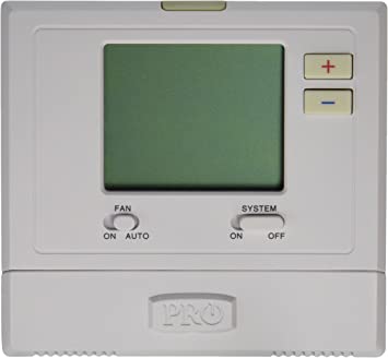
Getting to know your thermostat

- LCD

- Glow in the Dark Light Button
- Fan Switch
- System Switch
- Easy Change Battery Door
- Temperature Setpoint Buttons
Important:
The low battery indicator is displayed when the AA battery power is low. If the user fails to replace the battery within 21 days, the thermostat display will only show the low battery indicator as a final warning before the thermostat becomes inoperable.
NOTE: In applications where the thermostat will see temperatures below 40 degrees it is recommended that 1.5V AA lithium batteries be used instead of alkaline for increased battery life. (Extreme temperatures decrease the life of Alkaline batteries.)
Removing the private label badge
Gently slide a screwdriver into the bottom edge of the badge. Gently turn the screwdriver counterclockwise. The badge is held on by a magnet in the well of the battery door. The badge should pry off easily. Do not use force.
PRO 1
All Pro1 thermostats use the same universal magnetic badge. Visit our website at www.pro1iaq.com to learn more about our free private label program.
SUBBASE INSTALLATION
Caution: Electrical Hazard
Failure to disconnect the power before beginning to install this product can cause electrical shock or equipment damage
Mercury Notice:
All of Pro1’s products are mercury-free. However, if the product you are replacing contains mercury, dispose of it properly. Your local waste management authority can give you instructions on recycling and proper disposal.

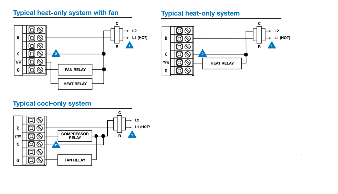
Wiring
- If you are replacing a thermostat, make note of the terminal connections on the thermostat that Is being replaced. In some cases, the wiring connections will not be color coded. For example, the green wire may not be connected to the G terminal.
- Loosen the terminal block screws. Insert Wires then retighten terminal block screws.
- Place non-flammable insulation into the wall opening to prevent drafts. Terminal Designations.
Warning: All components of the control system and the thermostat installation must conform to Class II circuits per the NEC Code.
Terminal Designations
- YW Heat relay or Compressor relay
- G Fan relay
- R Transformer power for cooling or heating
- C Common wire from system transformer
- Power supply
- Optional 24 VAC common connection when the thermostat is used in battery power mode
PRO1 Tips:
C terminal
The C (common wire) terminal does not have to be connected when the thermostat is powered by batteries.
Wire specifications
Use shielded or non-shielded 18-22 gauge thermostat wire.
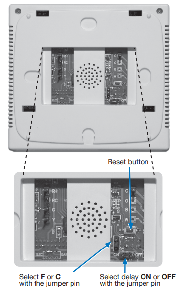
Important: The RESET button must be pressed after changing any switch or jumper pin setting. Batteries must be installed for this operation.
Fahrenheit/Celsius Display Select F or C with the jumper pin on the back of the thermostat.
Delay
The compressor delay will not allow the compressor to be turned on for 5 minutes after the last time the compressor was on. The cooling icon will flash during the delay period. Select OFF or ON with the jumper pin as desired.
TECHNICIAN SETUP
Selecting Heat or Cool
- Set the system switch to on.
- Hold down
 the key for 3 seconds to bring up the current mode.
 - Use to select the mode.
- Wait 10 sec for the thermostat to return to normal operation.
This thermostat has a technician setup menu for easy installer configuration. To set up the thermostat for your particular application:
- Set the system switch to
- Hold down key together for 3 seconds.
- Configure the installer options as desired using the table below.
- Use the keys to change the options below and the LIGHT key to move from one step to another.

PRO1 Tip
The temperature swing, sometimes called differential or cycle rate, can be customized for this individual application. For most applications choose a swing set that is as long as possible without making the occupants uncomfortable
MOUNT THERMOSTAT & BATTERY INSTALLATION
Mount Thermostat
Align the 4 tabs on the subbase with corresponding slots on the back of the thermostat, then push gently until the thermostat snaps in place.

Battery Installation
Battery installation is optional if the thermostat is hardwired (C terminal connected).

NOTE: In applications where the thermostat will see temperatures below 40 degrees it is recommended that 1.5V AA lithium batteries be used instead of alkaline for increased battery life. (Extreme temperatures decrease the life of Alkaline batteries.)
SPECIFICATIONS & CONTACT INFORMATION
- The display range of temperature… 20°F to 95°F (-6°C to 35°C)
- The control range of temperature. 25°F to 90°F (-4°C to 32°C)
- Load rating — – —— 1 amp per terminal, 1.5 amp maximum for all terminals combined
- Display accuracy ——- —- t1°F
- Swing (cycle rate or differential). – Heating is adjustable from 0.4°F to 2.0°F Cooling is adjustable from 0.4°F to 2.0°F
- Power source —-. -.- 18 to 30 VAC, NEC Class II, 50/60 Hz for hardwire (common wire) Battery power from 2 AA 1.5v batteries
- Operating ambient ** 20°F to +105°F (0°C to +41°C) -. –*
- Operating HUMIDITY.. 90% Non-condensing maXImum
- Dimensions of thermostat 4.7″W x 4.4″H x 1.1″D
Contact Us
Pro1 IAQ Inc. 1111 S. Glenstone Suite 2-100 Springfield, MO 65804
Toll-free: 1-888-Pro1iaq (776-1427)
Toll Number (Outside the USA): 330-821-3600
Web: http://www.pro1iaq.com
Hours of Operation: Monday – Friday 9 AM -6 PM Eastern
REFERENCE
Download Manual
Pro1 IAQ T771 Electronic Thermostat Installation Manual
![]()