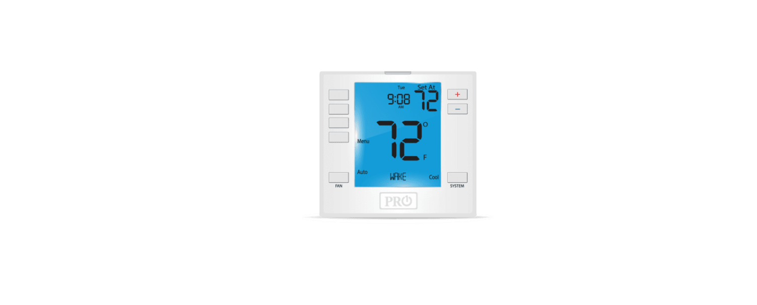
Pro1 Technologies T755 Non-Programmable Thermostat
Pro1 Technologies
P.O. Box 3377
Springfield, MO 65808-3377 Toll-Free: 888-776-1427
Web: www.pro1iaq.com
Hours of Operation: M-F 9 AM – 6 PM Eastern
Thermostat Application Guide
| Description | |
| Gas or Oil Heat | Yes |
| Electric Furnace | Yes |
| Heat Pump (No Aux. or Emergency Heat) | Yes |
| Heat Pump (With Aux. or Emergency Heat) | Yes |
| Multi-Stage Systems | Yes |
| Heat Only Systems | Yes |
| Cool Only Systems | Yes |
| Millivolt | Yes |
Power Type
- Battery Power
- Hardwire (Common Wire)
- Hardwire (Common Wire) with Battery
- Backup
A trained, experienced technician must install this product. Carefully read these instructions. You could damage this product or cause a hazardous condition if you fail to follow these instructions.
Installation Tips
Wall Locations
The thermostat should be installed approximately 4 to 5 feet above the floor. Select an area with average temperature and good air circulation. Pick an installation location that is easy for the user to access. The temperature of the location should be representative of the building.
Subbase Installation
- Horizontal Mount
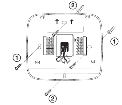 Vertical Mount
For vertical mount put one screw on the top and one screw on the bottom. For horizontal mount put one screw on the left and one screw on the right.
Do not install thermostat in locations
- Close to hot or cold air ducts
- That are in direct sunlight
- With an outside wall behind the thermostat
- In areas that do not require conditioning
- Where there are dead spots or drafts (in corners or behind doors)
- Where there might be concealed chimneys orpipes
Installation Tip
Electrical Hazard
Failure to disconnect the power before beginning to install this product can cause electrical shock or equipment damage.All of our products are mercury free. However, if the product you are replacing contains mercury, dispose of it properly. Your local waste management authority can give you instructions on recycling and proper disposal.
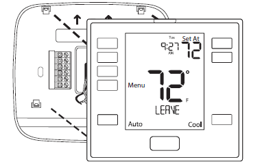
Thermostat Quick Reference
Align the 4 tabs on the subbase with corresponding slots on the back of the thermostat, then push gently until the thermostat snaps in place.
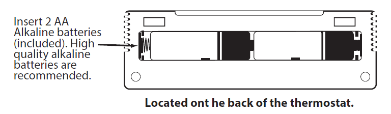
Battery Installation
Battery installation is optional if thermostat is hardwired (R and C terminal connected to 24V power).
Important:
High quality alkaline batteries are recommended. Rechargeable batteries or low quality batteries do not guarantee a 1-year life span.
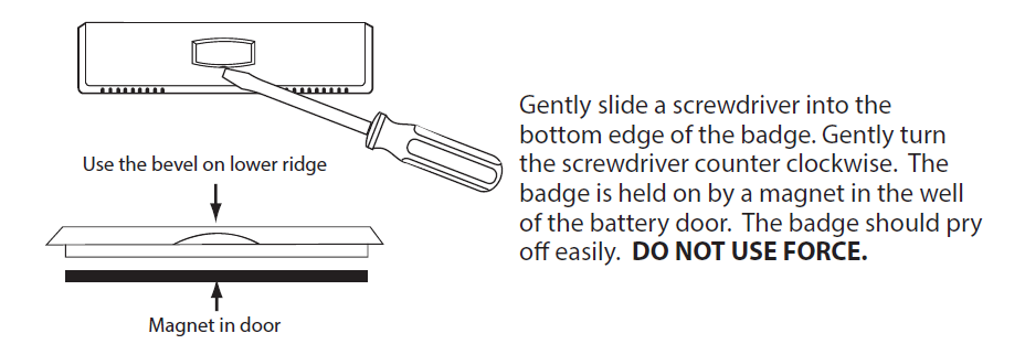
About The Private Label Badge
All of our thermostats use the same universal magnetic badge. Visit the company website to learn more about our free private label program.
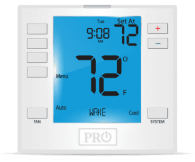
Getting to know your thermostat

- LCD Display
- Glow in the dark light button
- Fan Button
- System Button
- Temperature Setpoint Buttons
- User Buttons
- Private Label Badge
Getting to know your thermostat
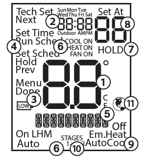
- Indicates the current room temperature
- Time and day of the week
- Low Battery Indicator: Replace batteries when this indicator is shown.
- Menu Options: Shows different options.
- Program Time Periods: This thermostat has 4 programmable time periods per day.
- System Operation Indicators: The COOL ON , HEAT ON or icon will display when the COOL, HEAT, or (fan) is on. The compressor delay feature is active if these are flashing.
- Hold is displayed when the thermostat program is permanently overridden.
- Setpoint: Displays the selected setpoint temperature.
- System: Indicates current mode of operation.
- Stages: Stage 1 will appear on the display when the 1st stage of heat or cool is on.
 2 will appear on the display when the 2nd stage of heat or cool is on.
  will appear on the display when the 3rd stage of heat
  or cool is on.
 - Globe: Globe is displayed if an energy efficient temperature has been selected.
Important
The low battery indicator is displayed when the AA battery power is low. If the user fails to replace the battery within 21 days, the screen will only show the low battery indicator but maintain all functionality. If the user fails to replace the batteries after an additional 21 days (days 22-42 since first “low battery” display) the setpoints will change to 55˚F (Heating) and 85˚F (Cooling). If the user adjusts the setpoint away from either of these, it will hold for 4 hours then return to either 55˚F or 85˚F. After day 63 the batteries must be replaced immediately to avoid freezing or overheating because the thermostat will shut the unit off until the batteries are changed.
Wiring
- If you are replacing a thermostat, make note of the terminal connections on the thermostat that is being replaced. In some cases the wiring connections will not be color coded. For example, the green wire may not be connected to the G terminal.
- Loosen the terminal block screws. Insert wires then retighten terminal block screws.
- Place nonflammable insulation into wall opening to prevent drafts.
Caution: Electrical Hazard
Failure to disconnect the power before beginning to install this product can cause electrical shock or equipment damage.All components of the control system and the thermostat installation must conform to Class II circuits per the NEC Code.
| Terminal | 2 Heat 2 Cool Conventional System | 2 Heat 2 Cool Heat Pump System | 3 Heat 2 Cool Heat Pump System |
| RC | Transformer power (cooling) | Transformer power (cooling) | Transformer power (cooling) |
| RH | Transformer power (heating) | Transformer power (heating) | Transformer power (heating) |
| C | Transformer common | Transformer common | Transformer common |
| B | Energized in heating | Heat pump changeover valve energized in heating | Heat pump changeover valve energized in heating |
| O | Energized in cooling | Heat pump changeover valve energized in cooling | Heat pump changeover valve energized in cooling |
| G | Fan relay | Fan relay | Fan relay |
| W/E | First stage of heat | First stage of emergency heat | First stage of emergency heat |
| W2 | Second stage of heat | Auxiliary heat relay, second stage of heat | Auxiliary heat relay, third stage of heat |
| Y | First stage of cool | First stage of heat & cool | First stage of heat & cool |
| Y2 | Second stage of cool | Second stage of cool | Second stage of cool & second stage of heat |
| S1/S2 | Remote Sensor | Remote Sensor | Remote Sensor |
Wiring Diagrams
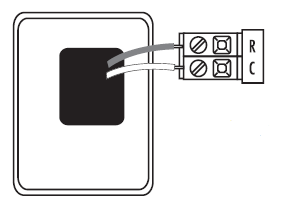
C Terminal
The C (common wire) terminal does not have to be connected when the thermostat is powered by batteries.
Wire Specifications
Use shielded or non-shielded 18-22 gauge thermostat wire.
Installation Tip: Do not overtighten terminal block screws, as this can damage the terminal block. A damaged terminal block can keep the thermostat from fitting on the subbase correctly or cause system operation issues. Max Torque = 6in-lbs.
- Power supply
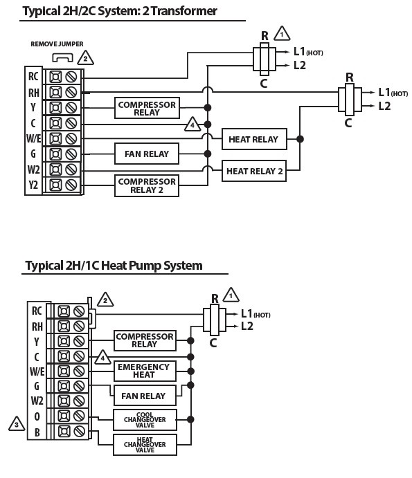
- Factory – installed jumper. Remove only when installing on a 2 transformer systems. Use either O or B terminals for changeover valve.
- Optional 24 VAC common connection when thermostat is used in battery power mode.
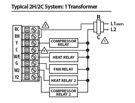
In many systems with no emergency heat relay a jumper can be installed between W/E and W2.
Note: This thermostat is hardwire powered when the 24V transformer is connected to the Common and RC terminals of the thermostat.
Note: In many systems with no emergency heat relay a jumper can be used between E and W2.
Typical Cool-Only System With Fan

Typical 2H/2C System: 2 Transformer
Features
Temporary and Permanent Hold Feature (If using programming)
When cool or heat is turned on, the thermostat will display HOLD and RUN SCHED on the left of your screen when you press the![]() or
or ![]() button.
button.
Temporary Hold: At this time if you do nothing, the temperature will remain at this setpoint temporarily for 4 hours.
Permanent Hold: If you press the HOLD key on the left of your screen, you will see HOLD appear below the setpoint temperature in the display. The thermostat will now permanently stay at this setpoint and can be adjusted using the or
or  keys.
keys.
To Return to Running Schedule: Press the RUN SCHED button on the left of your screen to exit either temporary or permanent hold.
Filter Change Reminder
If your installing contractor has configured the thermostat to remind you when the air filter needs to be changed, you will see FILT in the display when your air filter needs to be changed.
Resetting the filter change reminder: When FILT reminder is displayed, you should change your air filter and reset the reminder by holding down the second button from the top left side of the thermostat for 3 seconds.
Tech Settings
This thermostat has a technician setup menu for easy installer configuration. To set up the thermostat for your particular application:
- Press the MENU button.
Press and hold the TECH SET button for 3 seconds. This 3 second delay is designed so that homeowners do not accidentally access the installer settings. - Configure the installer options as desired using the table below. Use the or keys to change settings and the NEXT or PREV key to move from one step to another.
Note: Only press the DONE key when you want to exit the Technician Setup options. - Press the DONE key to exit.
|
Filter Change Reminder |
This feature will flash a reminder after the elapsed run time to remind the user to change the filter. A setting of “OFF” will disable this feature. | OF
FILTER |
You can adjust the filter change reminder from “OFF” to 2000 hours of runtime in 50 hour increments. | OFF |
|
Room Temperature Calibration |
This feature allows the installer to change the calibration of the room temperature display. For example, if the thermostat reads 70˚ and you would like it to read 72˚ then select +2. | 0
CALIBRATE |
You can adjust the room temperature display to read up to 4˚above or below the factory calibrated reading. | 0˚F |
|
Cooling Swing |
The swing setting often called “cycle rate”, “differential” or “anticipation” is adjustable. A smaller swing setting will cause more frequent cycles and a larger swing setting will cause fewer cycles. | 0.5
COOL SWING |
The cooling swing setting is adjustable from 0.2˚ to 2˚. For example: A swing setting of 0.5˚ will turn the
cooling on at approximately 0.5˚ above the setpoint and turn the cooling off at approximately 0.5˚ below the setpoint. |
0.5˚ |
|
Heating Swing |
The swing setting often called “cycle rate”, “differential”, or “anticipation” is adjustable. A smaller swing setting will cause more frequent cycles and a larger swing setting will cause fewer cycles. | 0.4
HEAT SWING |
The heating swing setting is adjustable from 0.2˚ to 2˚. For example: A swing setting of 0.5˚ will turn the heating on at approximate- ly 0.5˚ below the setpoint and turn the heating off at 0.5˚ above the setpoint. |
0.4˚ |
|
PTAC Mode |
This setting allows the thermostat to operate a PTAC. This will allow for multiple fan speeds selectable in the next two tech settings. | OF
PTAC MODE |
Use the and buttons to select ON/OFF. | ON |
|
PTAC Fan Speeds (Only displayed if PTAC mode is ON) |
This setting allows you to choose the number of fan speeds the thermostat will control.
G = Low Speed Fan B/O = Medieum Speed Fan Y2 = High Speed Fan |
2
FAN SPEEDS |
Use the and buttons to select , 2 or 3.
1. Speeds: ON, Auto 2. Speeds: Low, High, Auto 3. Speeds: Low, Med, High, Auto |
2 |
| PTAC Medium | This setting will select the terminal for medium fan speed operations. The selected terminal cannot be used for reversing valve operations when heat pump is enabled. | 0
MED FAN TERM |
Use the and buttons to select O/B terminals. |
0 |
| Fan Speed | ||||
| Terminal | ||||
| (Only displayed | ||||
| if PTAC mode is | ||||
| ON and PTAC fan | ||||
| speeds is set to 3) | ||||
|
Heat Pump |
When turned on the thermostat will operate a heat pump. EM. Heat will show as an option in the system switch tech setting.
Use the and button to adjust. |
OF
HEAT PUMP |
OFF configures the thermostat for conventional systems.
ON configures the thermostat for heat pump systems. |
OFF |
Swing Setting Tip
The second stage will turn on at 2x the swing setting. The second stage will turn off when 1x the swing is reached. For example, if the swing setting is .5 degrees for heating and the thermostat is set at 70˚F, the first stage will turn on at approximately 69.5˚F. The second stage will turn on at 69˚F. The second stage will turn off at 69.5˚F and the first will turn off at 70.5˚F. If the third stage is used, it will turn on at 68.5˚F and turn off at approximately 69˚F.
|
System Stages |
This setting allows you to select the number of heat and cool stages. | 2H2C
SET STAGES |
Use the and buttons to select 1H/1C, 2H/1C, 2H/2C, 3H/1C, 3H/2C, 4H/2C.
Note: Heat and cool choices are limited based on conventional, heat pump, or PTAC system configuration. |
2H |
|
System Set |
You can configure the system switch for the particular application. Heat – Off – Cool, Heat – Off, Cool – Off, Heat – Off – Cool – Auto.
Note: Emergency Heat is available in heat pump mode only. |
SYSTEM SET
AutoOff Em.Heat Cool |
Use the or buttons until the desired application is flashing. AUTO = (Auto Changeover) | Heat |
| Off | ||||
| Cool | ||||
| Dual Fuel Auxiliary For Heat Pump
(Only displayed if heat pump is set to ON) |
This setting allows the system to run Gas, Oil, Propane or any
other types of auxiliary heat. The thermostat will default to electric auxiliary heat in heat pump applications. |
OF
DUAL FUEL |
Use the and but- tons to select ON/OFF. |
OFF |
|
Electric or Gas Fan Operation
(Only displayed if heat pump is set to ON) |
Select GAS to have the system control the fan during a call for heat, select Electric to have the thermostat control the fan during a call for heat.
Note: If heat pump is set to “ON” this step will not show, and will default to ELECTRIC. |
GAS
FAN SET |
Use and buttons to change the setting. |
GAS |
| Satisfy Setpoint Staging
(Only displayed if there are more than one stage of heat or cool) |
This feature allows the thermostat to keep multiple stages of heat or cool energized until the setpoint is satisfied. | OF
SS STAGING |
Use the or buttons to turn on of off. |
OFF |
| Staging Delay
(Only displayed if there are more than one stage of heat or cool) |
This feature allows a delay to occur if an additional stage is needed. This allows the previous stage extra time to satisfy the setpoint.
Note: Will not show if using outdoor sensor with balance point temperature. |
OF
STAGING DELAY |
Use the or key to select OFF, 5, 10, 15, 30, 45,
60, or 90 minutes. |
OFF |
|
Minimum Compressor On Time |
This feature allows the installer to select the minimum run time for the compressor. For
example, a setting of 4 will force the compressor to run for at least 4 minutes every time the compressor turns on, regardless of the room temperature. |
OF
MIN COMP ON |
You can set the minimum compressor run time to “OFF”, “3”, “4”, or “5” minutes.
If 3, 4 or 5 is selected, the compressor will run for at least the selected time before turning off. Use the and buttons to change the setting. |
OFF |
|
Compressor Short Cycle Delay |
The compressor short cycle delay protects the compressor from “short cycling”. This feature will not altlow the compressor to be turned on for 5 minutes after it was last turned off. |
COMP DELAY |
Selecting “ON” will not allow the compressor to be turned on for 5 minutes after the last time the compressor was on. Select “OFF” to remove this delay. Use the and buttons to change the setting. |
ON |
|
Cooling Fan Delay |
The cooling fan delay setting will delay the fan from coming on in cool mode and keep it running after the compressor shuts off for a short time to save energy in some systems. | OF
COOL FAN DL |
You can set the cooling fan delay to OFF, 10, 30, 60 or 90
seconds. If 10, 30, 60, or 90 is selected the fan will not turn on for that many seconds when there is a call for cool and will run for that many seconds after satisfying a call for cool. |
OFF |
|
Program Options |
You can configure this thermostat to have 7 Day, 5+1+1 programming or non programmable. | 5d
PROG |
Use the and key to select 7d for 7 Day, 5d
for 5+1+1, or 0d for non programmable. |
5d |
|
Pro Recovery |
This feature will start heating and cooling early to bring the building temperature to its programmed setpoint by the beginning of the WAKE, RETURN and OCCUPIED
time periods. |
PRO RECOVERY |
Use the or key to select on or off. |
ON |
| Heat Setpoint Limit | This feature allows you to set a maximum heating setpoint limit. The setpoint temperature cannot be raised above this value. | HE
HEAT LIMIT |
Use the or key to select the maximum heat setpoint and the minimum cooling setpoint. | 90˚F |
| Cool Setpoint Limit | This feature allows you to set a minimum cooling setpoint limit. The setpoint temperature cannot be lowered below this value. | CO
COOL LIMIT |
Use the or key to select the minimum cooling setpoint. | 44˚F |
|
˚F or ˚C |
This feature allows you to display temperatures in either Fahrenheit or Celsius. | oF
F OR C SET |
˚F for Fahrenheit
˚C for Celsius |
˚F |
|
12 or 24 Hour Clock |
You can select either a 12 or 24 hour clock setting. | 12
CLOCK SET |
Use the or key to select 12 or 24 hour clock. | 12H |
|
Display Light |
The display light can be configured to stay on all the time or turn on when any key is pressed. There are LOW and
HIGH selections for continuous ON selection. NOTE: The thermostat will need to be hardwired in order for the LOW and HIGH display light functions to work properly. “ALWAYS ON LIT” will alter- nate in the text field with “HARDWIRE ONLY” when HIGH is selected. These prompts will alternate every three seconds.
If the thermostat is hardwired this feature will default to LOW. |
dL
ALWAYS ON LIT
dL HARDWIRE ONLY |
Use the and
buttons to select OFF, LOW, or HIGH. OFF configures the display light to come on when the light key or any button is pressed. LOW configures the display light to stay on at a low intensity constantly. When a button is pressed, the display light will transition to high intensity. HIGH configures the display light to remain on at high intensity all the time. |
OFF
If Battery Powered
LOW If Hardwired |
Contractor Call Number Note
If contractor call number is selected ON, the phone number entered will show in the display if there has been a continuous call for heating or cooling for 24 hours or if the light button is held down for 3 seconds. To remove the phone number from the display, hold the light button down for 3 seconds.
|
Contractor Call Number |
This feature allows you to put your phone number in the display. You can choose ON or OFF.
Notes: If contractor call number is selected ON, the phone number entered will show in the display if there has been a continuous call for heating or cooling for 24 hours or if the light button is held down for 3 seconds. To remove the phone number from the display, hold the light button down for 3 seconds. |
OF
PHONE NUMBER |
If selected ON, you will see the input screen after pressing NEXT STEP. Use the
or button to select the desired number and the FAN or SYSTEM key to move from one character to another. See note below for operation. |
OFF |
| Remote Sensor Operation
(Only displayed if a sensor is connected to S1 and S2 terminals) |
You can configure the thermostat for one of three remote sensor applications: 0 No Sensor, 1
Indoor, 2 Outdoor, 3 Floor. |
0 | Use the left and right arrows to select one of three options. View the S1/ S2 terminal chart on next page for an explanation of these options. |
0 |
| REMOTE MODE | ||||
|
Local Temp Sensor (Only displayed if remote sensor setting is set to 1) |
You can disable the sensor on the T855SH thermostat. At least one R251S indoor remote sensor must be connected to disable the
local T855S sensor. Note: Will only show if remote sensor is set to 1. |
LOCAL TEMP |
ON enables local T855SH sensor. OFF disables local T855SH sensor. |
ON |
| Number | Enables the use of up to sixteen indoor sensors R251S. Note: Will only show Remote Sensor is set to 1 and Local Temp Sensor is
set to on. |
1
NUMBER REMOTE |
You can use 1, 4, 9, or 16 indoor sensors. Refer to the R251S Install Manual for de- tailed connection information |
1 |
| of Indoor | ||||
| Remotes | ||||
| (Only displayed | ||||
| if remote sensor | ||||
| setting is set to 1) | ||||
| Dual Fuel Balance Point
(Only displayed if remote sensor setting is set to 2 and Dual Fuel AUX = On) |
An outdoor temperature above balance point will cause the thermostat to energize the Y terminal(s) only in calls for heat. An outdoor temperature below balance point will cause the thermostat to energize the W2 terminal only in calls for heat. | OF
BALANCE POINT |
Use the and buttons to select OFF, 10, 15, 20, 25,
30, 35, 40, 45, 50 degrees. |
OFF |
| Options | Mode | Description | Requires |
| 1 | Indoor | The local and remote temperatures are averaged. | R251S |
| 2 | Outdoor | The outdoor temperature is flashed in clock. | R250S |
| 3 | Floor | The floor temperature is shown in tech. | R250S |
|
Balance Point Run Time (Only displayed if remote sensor setting is set to 2) |
Balance point run time will allow the W2 auxiliary terminal to ener- gize even if outdoor temperature is above selected balance point temperature. If enabled, auxiliary will energize for the current cycle after the balance point run time has expired.
Note: Only shows if Balance Point is set to an outdoor temperature. |
OF
BP RUN TIME |
Off, 15, 30, 45, 60, 75, 90 |
OFF |
|
Floor Temperature (Only displayed if remote sensor setting is set to 3) |
The temperature of the floor sensor will be displayed.
Note: Only shows when REOP is set to 3. Use and buttons to adjust. |
76
FLOOR TEMP |
N/A |
N/A |
|
Floor High Limit (Only displayed if remote sensor setting is set to 3) |
This setting allows you to set a maximum floor temperature
limit for heat. Heat will be locked out when the floor temperature is above this value. Note: Only shows when REOP is set to 3. |
86
HIGH LIMIT |
Use the or buttons to select the High Limit for the floor sensor.35 – 120 |
86 |
|
Floor Low Limit (Only displayed if remote sensor setting is set to 3) |
This setting allows you to set a minimum floor temperature
limit for heat. Heat will turn on automatically when the floor temperature is below this value. Note: Only shows when REOP is set to 3. |
50 | Use the or keys to select the Low Limit for the floor sensor.
35 – 120 |
50 |
|
LOW LIMIT |
Programming
Set Time
- With system switch set to OFF, press the MENU button
- Press SET TIME
- Day of the week will be flashing. Use the or key to select the current day of the week.
- Press NEXT STEP
- The current hour is flashing. Use the or key to select the current hour. When using 12-hour time, make surethe correct a.m. or p.m. choice is selected.
- Press NEXT STEP
- Minutes are now flashing. Use the or key to select current minutes.
- Press DONE when completed.
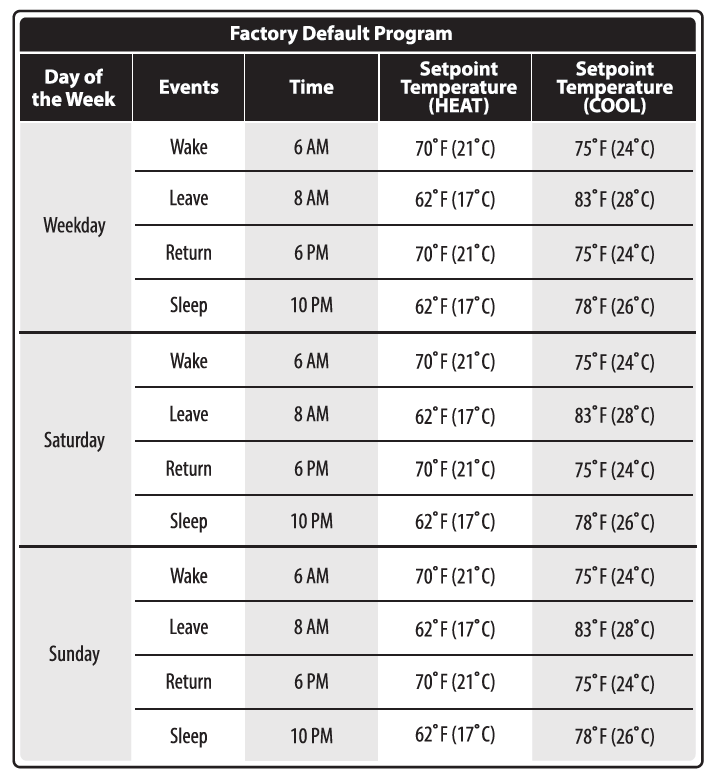
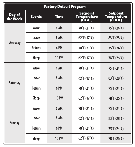
Programming
All of our programmable thermostats are shipped with an energy saving pre-program. You can customize this default program by following the steps on the next page. There are four time periods for each program (WAKE, LEAVE, RETURN, SLEEP).
A Note About Auto Changeover
In Auto you have the ability to switch between Auto Heat or Auto Cool by pressing the system key. This can be done once the current mode has reached its setpoint. For example: if in Auto Heat, the heat setpoint must be satisfied before the thermostat will allow you to switch to Auto Cool. You can switch out of Auto by holding down the system key. To get back into Auto, you must toggle the system key to Auto.All of our programmable thermostats are shipped with an energy saving pre-program. You can customize this default program by following the steps on page 16. There are four time periods for each program (WAKE, LEAVE, RETURN, SLEEP).
Set Program Schedule 5+1+1 or 7 Day
To customize your program schedule, follow these steps:
- Select HEAT or COOL with the system switch. Note: You have to program heat and cool each seperately.
- Press the MENU button (If menu does not appear first press RUN SCHED)
- press SET SCHED. Note: Monday-Friday or (Monday if in 7 Day) is displayed and the WAKE icon is shown. You are now programming the wake time period for that day.
- Time is flashing. Use the or key to make your time selection for that day’s WAKE time period. Note: If you want the fan to run continuously during this time period, select ON with e FAN key
- Press NEXT STEP
- The setpoint temperature is flashing. Use the or to make your setpoint selection for that day’s WAKE time period.
- press NEXT STEP
- Repeat steps 4 thru 7 for that day’s LEAVE time period, RETURN time period, and SLEEP time period.
If in 5+1+1 Programming
Repeat steps 4 thru 8 for the Saturday + Sunday time periods.
If using 7- Day Programming
Use these same steps for every individual day.
You can use the table below to plan your customized program schedule.
Specifications
- The display range of temperature … 41˚F to 95˚F (5˚C to 35˚C)
- The control range of temperature…. 44˚F to 90˚F (7˚C to 32˚C)
- Load Rating……………………………………….. 1 amp per terminal, 1.5 amp
- maximum all terminals combined
- Swing (cycle rate or differential) …… Heating is adjustable from 0.2˚ to 2.0˚
- Cooling is adjustable from 0.2˚ to 2.0˚
- Power source …………………………………….18 to 30 VAC, NEC Class II, 50/60 Hz
- for hardwire
- Battery power from 2 AA Alkaline
- batteries
- Operating ambient …………………………. 32˚F to +105˚F (0˚C to +41˚C)
- Operating humidity ………………………… 90% non-condensing maximum
- Dimensions of thermostat …………….. 4.7” W x 4.3” H x 0.9” D
Reference
Download Manual:
Pro1 Technologies T755 Non-Programmable Thermostat Installational Manual
OTHER MANUALS
Pro1 Technologies T755 Non-Programmable Thermostat Operational Manual
Pro1 Technologies T755 Non-Programmable Thermostat Product Specifications Guide
![]()
Pro1 Technologies T755 Non-Programmable Thermostat Installational Manual
Leave a Reply