Pioneer TST-MLD-I-WP24 REMOTE CONTROL Programmable THERMOSTAT
Compatible with
- RB, CB, UB, FB Fan Coil Units
- RYB, UYB, CYB, FYB Split Systems
IMPORTANT NOTICE: Please read this manual carefully before installing or operating your wired remote controller. Make sure to save this manual for future reference.
- This manual gives detailed description of the precautions that should be brought to your attention during operation.
- In order to ensure correct service of the wired controller please read this manual carefully before using the unit.
- For convenience of future reference, keep this manual after reading it.
- All the pictures in this manual are for explanation purpose only. There may be slightly different from the wired remote controller you purchased (depend on model). The actual shape shall prevail.
Safety precaution
WARNING
- Please entrust the distributor or professionals to install the unit.
- Installation by other persons may lead to imperfect installation, electric shock or fire.
- Adhere to this installation manual.
- Imporper installation may lead to electric shock or fire.
- Reinstallation must be performed by professionals.
- Do not uninstall the unit randomly.
- Random uninstalling may lead to abnormal operation, heating or fire of the air condition.
NOTE
- Do not install the unit in a place vulnerable to leakage of flammable gases.Once flammable gases are leaked and left around the wire controller, fire may occur.
- Do not operate with wet hands or let water enter the wired controller. Otherwise, an electric shock may occur.
- The wiring should adapt to the wire controller current. Otherwise, electric leakage or heating may occur and result in fire.
- The special cables shall be applied in the wiring. No external force may be applied to the terminal. Otherwise, wire cut and heating may occur and result in fire.
Installation accessory
Select the installation location
- Don’t install at the place where cover with heavy oil, vapor or sulfurated gas, otherwise, this product would be deformed that would lead to system malfunction.
Preparation before installation
- Please confirm that all the following parts you have been supply.
| No. | Name | Qty. Remarks | |
| 1 | Wire controller | 1 | |
| 2 | Installation and owner’s manual | 1 | |
| 3 | Screws | 3 | M3.9X25 (For Mounting on the Wall) |
| 4 | Wall plugs | 3 | For Mounting on the Wall |
| 5 | Screws | 2 | M4X25 (For Mounting on switch box) |
| 6 | Plastic screw bars | 2 | For fixing on switch box |
| 7 | Battery | 1 | |
| 8 | The connective wires group | 1 | Optional |
| 9 | Screw(Only available for the shielded wire with connection plug) | 1 | M4X8(For Mounting the connective wire group) |
| 10 | Magnetic ring | 1 | Use the magnetic ring to hitch the connective cable of the wire controller. |
- Prepare the following assemblies on the site.
| No. | Name | Qty.(embeded into wall) | Specification
(only for reference) |
Remarks |
| 1 | Switch box | 1 | ||
| 2 | Wiring Tube(Insulating Sleeve and Tightening Screw) | 1 |
Precaution of installing the wire controller
- This manual provides the installation method of wired controller. Please refer to the wiring diagram of this installation manual to connect the wire controller with indoor unit.
- The wired controller works in low voltage loop circuit. Forbid to directly contact the cable of high voltage above,like 115V, 220V,380V, and don’t wire this kind of wire in the said loop; wiring clearance between configured tubes should be at the range of 300~500mm or above.
- The Shielded wire of the wired controller must be grounded firmly.
- Upon finish the wire controller connection, do not employed tramegger to detect the insulation.
Installation method
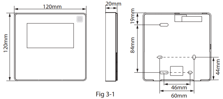
Wired remote controller structural dimensions
Remove the upper part of wired controller

- Insert a slot screwdriver into the slots in the lower part of the wired controller (2 places), and remove the upper part of the wire controller. (Fig.3-2)
NOTE: The PCB is mounted in the upper part of the wired controller. Be careful not to damage the board with the slot screwdriver.
Fasten the back plate of the wired controller
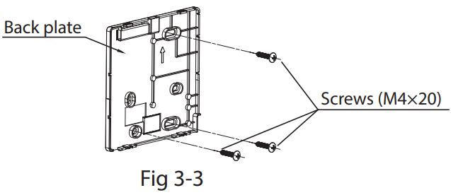
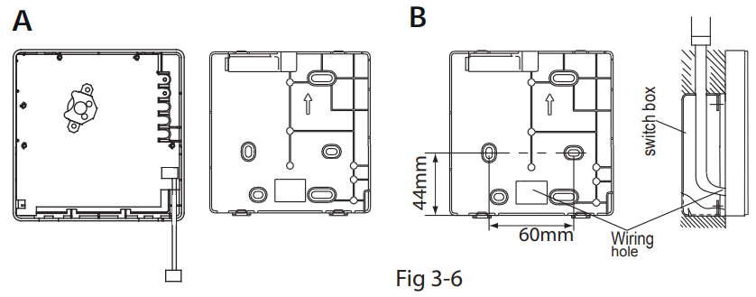
- For exposed mounting, fasten the back plate on the wall with the 3 screws (M4×20) and plugs. (Fig.3-3)
- Use two M4X25 screws to install the back cover on the 86 switch box, and use one M3.9X25 screw to fix to the wall.
NOTE: Put on a flat surface. Be careful not to distort the back plate of the wire controller by overtightening the mounting screws.
Battery installation
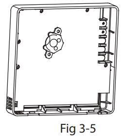
- Put the battery into the installationsite and make sure the positive side of the battery is in accordance with the positive side of installation site.(See Fig.3-5)
- Please set the time corrected on the first time operation. Batteries in the wire controller can time under power failure which ensure the time keep right. When the power restores, if the time displayed is not correct, it means the battery is dead and replace the battery.
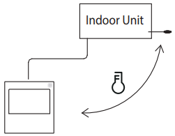
Wire with the indoor unit
- indoor unit
- notch the part for the wiring to pass through with nippers, etc.
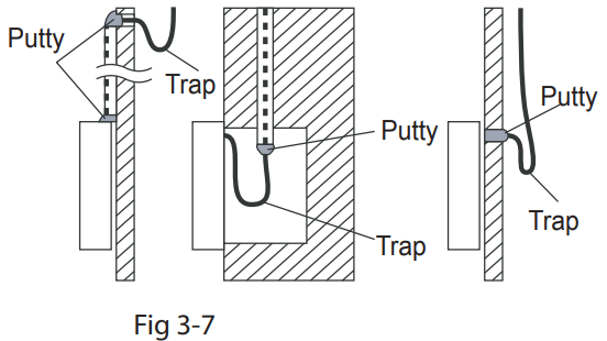
NOTE: DO NOT allow water to enter the remote control. Use the trap and putty to seal the wires.
Installation Diagram

- Connect the wire from the master control board of the indoor unit to a connecting cable. Then connect the other side of the connecting cable to the remote control.
NOTE
- Be sure to reserve a length of the connecting wire for periodic maintenance.
- If there is a connection lug at the end of the shielded wire, the connection lug should be properly grounded.
Reattach the upper part of the wire controller

- After adjusting the upper case and then buckle the upper case; avoid clamping the wiring during installation. (Fig 3-9)
- All the pictures in this manual are for explanation purpose only.
- Your wire controller may be slightly different. The actual shape shall prevail.
Specification
| Input voltage | KJR-120X1/TFBG-E: DC 5V, KJR-120X2/TFBG-E: DC 12V |
| Ambient temperature | -5~43℃(23~110℉) |
| Ambient humidity | RH40%~RH90% |
Wiring specifications
| Wiring type | Size | Total length |
| shielded vinyl cord or cable | 0.5-1.25mm 2 | <50m(164’) |
Feature and function of the wired controller
Feature
- LCD display.
- Malfunction code display: it can display the error code, helpful for service.
- 4-way wire layout design, no raised part at backside, more convenient to place the wires and install the device.
- Room temperature display.
- Weekly Timer.
Function
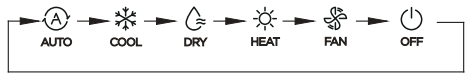
- Mode: choose Auto-Cool-Dry- Heat -Fan
- Fan speed: Auto/Low/Med/High speed
- Swing(on some models)
- Timer ON/OFF
- Temp setting
- Weekly timer
- Follow me
- Turbo
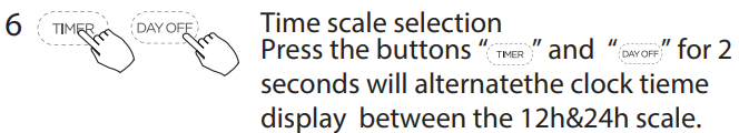
- 24-hour System
- 12-hour System
- Auto-restart
- Individual louver control (on some models)
- Automatic airflow test
- Child Lock
- LCD display
- Clock
- Panel function (on some models)
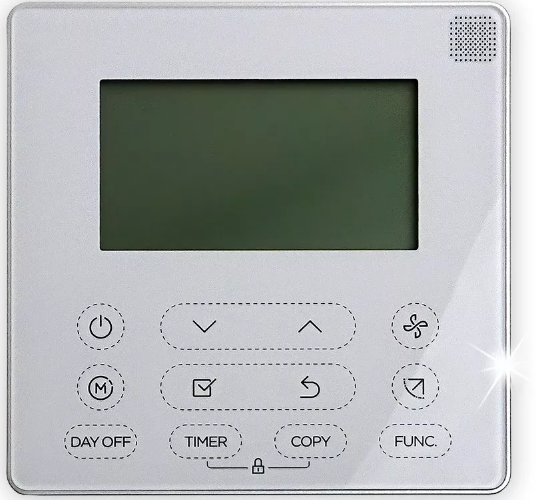
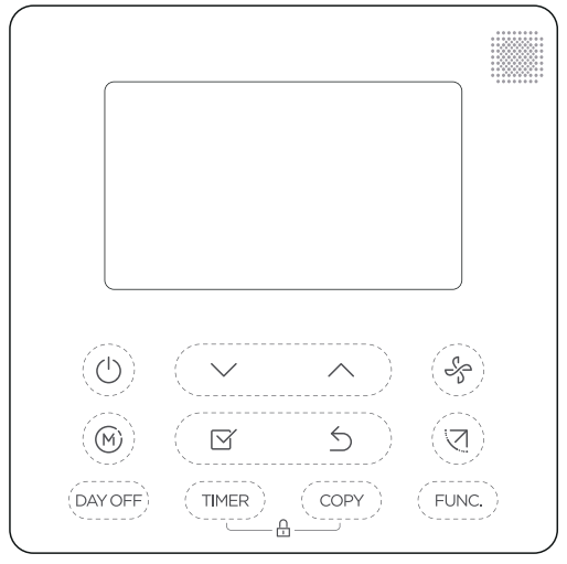
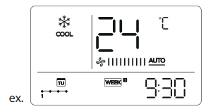
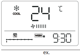
Name on the LCD of the wired controller
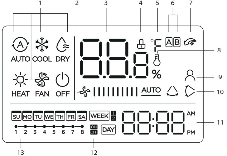
- Operation mode indication
- Fan speed indication
- Temperature display
- Lock indication
- °C / °F indication
- Main unit and secondary unit indication
- Turbo function indication
- Room temperature indication
- Follow Me function indication
- Left-right swing indication (some models)
- Clock display
- On/Off timer
- Timer display
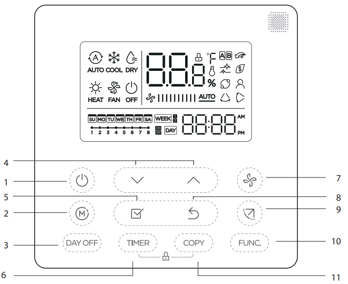
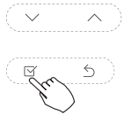
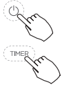
- POWER button
- MODE button
- DAY OFF/DEL button
- ADJUST button
- CONFIRM button
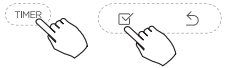
- TIMER button
- FAN SPEED button
- BACK bottom
- SWING bottom
- FUNC. button
- COPY button
Preparatory operation
Set the current day and time
Operation
To start/stop the operation
 Press the Power button.
To set the operation mode
 Operation mode setting
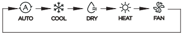
- Press the Mode button to set the operation mode.(Heat function is invalid for cool only type unit)
Room temperature setting
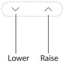
- Press the button“
 ”or “
”or “  ” to set the room temperature.
 - Indoor Setting Temperature Range :
- 17~30°C(62~86°F ).
- °C & °F scale selection(on some models)
- Press the buttons “ ” and “ ” for 3 seconds will alternate the temperature display between the °C & °F scale.
 Fan speed setting
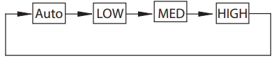
- Press the Fan speed button to set the fan speed.
- (This button is unavailable when in the mode of Auto or Dry)
keypad tone setting
- Press the buttons Swing and FUNC. for 3 seconds to close the keypad tone.
- Press the buttons again for 3 seconds to open the keypad tone.
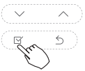
![]() Child lock function
Child lock function
- Press the buttons “
 ” and “
  ” for 3 seconds to activate the child lock function and lock all buttons on the wire controller.
 - Press the buttons again for 3 seconds to deactivate the child lock function.
- When the child lock function is activated,the
 mark appears.
Swing function(For the unit left & right auto swing models only)
 Up-Down swing
- Press the SWING button to start the up-down swing function. Press it again to stop.
- When the Up-Down swing function is activated, the
 mark appears.
- Left-Right swing
- Press the Swing button long to start the Left-Right swing function.
- Press it again to stop. When the Left-Right swing function is activated, the mark appears.
Swing function(For the unit without left & right auto swing function models)
Up-Down airflow direction and swing
- Use Swing button to adjust the Up-down airflow direction.
- Press the button every time, the louver swings 6 degrees.
- Press and hold the button for 2 seconds,it turns into up-down swing mode, press ti again to stop. When the Up-Down swing function is activated,the mark appears. (Not applicable to all the models)
- The operation can refer to the following instructions for the unit with four Up-Down louvers can be operated individually.
- Press the Swing button to activate the Up-Down adjusting louver function.
- The mark will flash.(Not applicable to all the models)
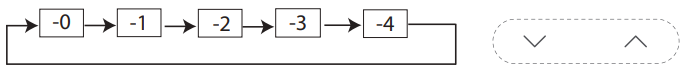
- The
- Pressing the button “ ” or“ ” can select the movement of four louvers.Each time you push the button,the wire controller select in a sequence that goes from:(the icon -0 means the four louvers move at the same time.)
- And then use Swing button to adjust the Up-Down airflow direction of the selected louver.
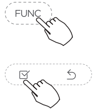
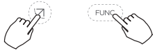
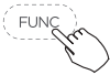
- Press the FUNC. button to set the turbo or Ifeel function.
- The select function icon will flash then press the Confirm button to confirm the setting.
- Press the FUNC. button to set the turbo or Ifeel function.
Turbo function (on some models)
 Under COOL/HEAT mode,press the FUNC. button to activate the turbo function. Press the button again to deactivate the turbo function. When the turbo function is activated,the
 mark appears.
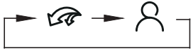
Follow me function indication
- Press the FUNC. button to select whether the room temperature is detected at the indoor unit or the wire controller.
- Press the button again to cancel the follow me function.
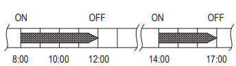
Timer functions
![]()
- WEEKLY timer
- Use this timer function to set operating times for each day of the week.
- On timer
- Use this timer function to start air conditioner operation.
- The timer operates and air conditioner operation starts after the time has passed.
- Off timer
- Use this timer function to stop air conditioner operation.
- The timer operates and air conditioner operation stops after the time has passed.
- On and Off timer
- Use this timer function to start and stop air conditioner operation.The timer operates and air conditioner operation starts and stops after the time has passed.
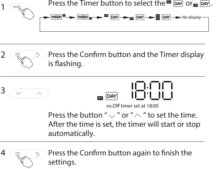
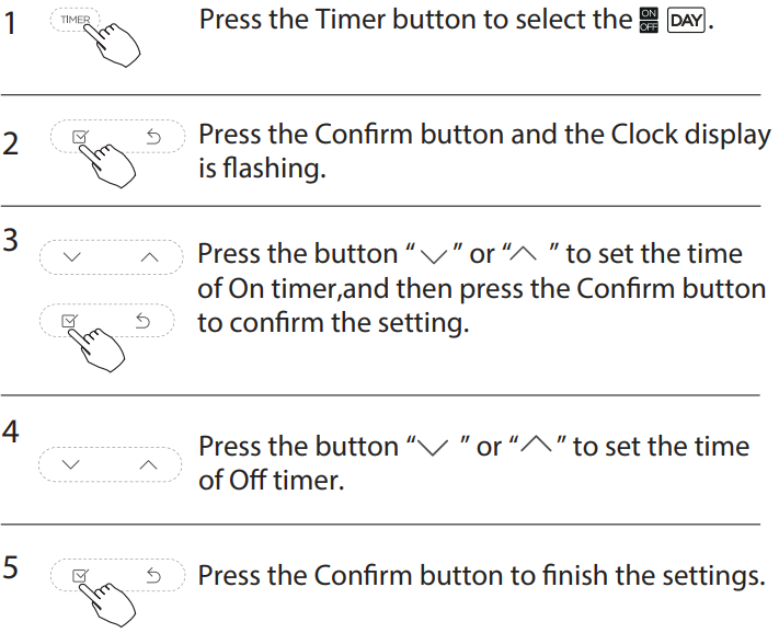
To set the On or Off TIMER
To set the On and Off TIMER
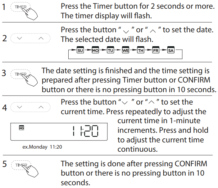
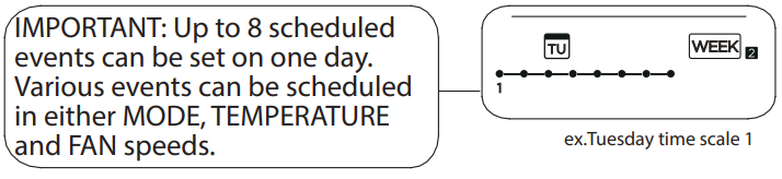
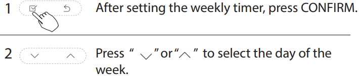
Weekly Timer 1
- Weekly timer setting
 Press the Timer button to select the
 and then press the Confirm button to confirm.
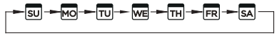
- Day of the week setting
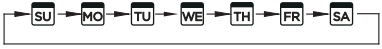
 Press the button “ ” or “ ” to select the day of the week and then press the Confirm button to confirm the setting.
- ON timer setting of timer setting 1
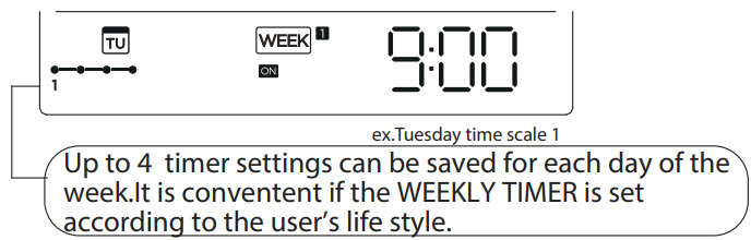
- Press the button “ ” or “ ” to set the time of On timer and then press the Confirm button to confirm the setting.
- Off timer setting of timer setting 1
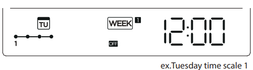
 Press the button “ ” or “ ” to set the time of Off timer and then press the Confirm button to confirm the setting.
- Different timer settings can be setted by repeating step 3 to 4.
- Other days in one week can be setted by repeating step 2 to 5.
NOTE: The weekly timer setting can be returned to the previous step by pressing Back button.The time of timer setting can be delete by pressing Day o botton The current setting will be restored and withdrawn the weekly timer setting automatically when there is no operation for 30 seconds.
WEEKLY timer operation
To activate WEEKLY TIMER operation
 Press the Timer button while is displayed on the LCD.
To deactivate WEEKLY TIMER operation
- Press the Timer button while is disappear from the LCD.
To turn off the air conditioner during the weekly timer
- If press the Power button once and quickly, the air conditioner will turn off temporarily. And the air conditioner will turn on automatically until the time of On timer.
- ex. If press the POWER button once and quickly at 10:00, The air conditioner will turn on at 14:00.
- When press the Power button for 2 seconds, the air conditioner will turn off completely,at the same time cancel the timing function.
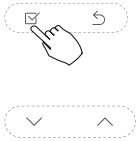
To set the DAY OFF (for a holiday)
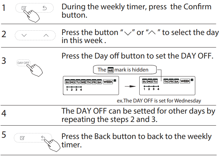
To cancel: Follow the same procedures as those for setup.
Notes
- The DAY OFF setting is cancelled automatically after the set day has passed.
DELAY function
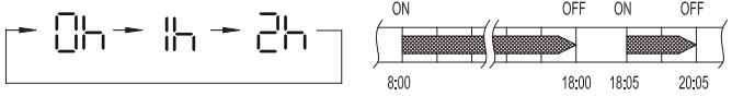
 During the weekly timer, pressing the Del button once, display ”
  “. Press this button twice, display “
 ” and wait 3 seconds to confirm. It means the unit will override 1 hours; Press this button three times,display “2h ” and wait 3 seconds to confirm. It means the unit will override 2 hours;
- ex. If press the DEL button to select “ ” at 18:05 , The air conditioner will delay to turn off at 20:05.
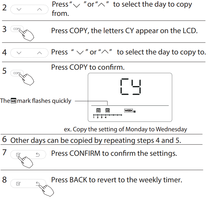
Copy out the setting in one day into the other day
A reservation made once can be copied to another day of the week.The whole reservation of the selected day of the week will be copied. The effective use of the copy mode ensures ease of making reservations.
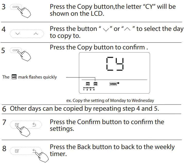
- Weekly timer setting
 Press Timer to select the
 and press Confirm.
- Day of the week setting
 Press “ ” or “ ” to select the day of the week and then press CONFIRM.
- ON timer setting of timer setting 1
- Press “ ” or “ ” to select the setting time. The setting time, mode, temperature and fan speed appear on the LCD.
- Press CONFIRM to enter the setting time process.
- Time setting
- Press “ ” or “ ” to set the time then press CONFIRM.
- Operation mode setting
- Press “ ” or “ ” to set the operation mode then press CONFIRM.
- Room temperature setting
- Press “ ” or “ ” to set the room temperature then press CONFIRM.
- NOTE: This setting is unavailable in the FAN or OFF modes.
- Fan speed setting
 Press “ ” or “ ” to set the fan speed then press CONFIRM.
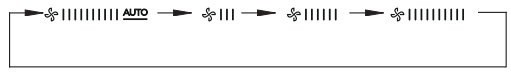
- NOTE: This setting is unavailable in the AUTO, DRY or OFF modes.
- Different scheduled events can be set by repeating steps 3 through 7.
- Additional days, in a one week period, can be set by repeating steps 3 through 8.
NOTE: The weekly timer setting can be returned to the previous step by pressing BACK. The current setting is restored. The controller will not save the weekly timer settings if there is no operation within 30 seconds.
WEEKLY timer operation
- To start: Press Timer to select the, and then the timer starts automatically.
 To cancel: Press the Power buttons for 2 seconds to cancel the timer mode.
- The timer mode can also be canceled by changing the timer mode using Timer.
To set the DAY OFF (for a holiday)

- To cancel, follow the same procedures used for setup.
NOTE: The DAY OFF setting is cancelled automatically after the set day has passed.
Copy out the setting in one day into the other day
A scheduled event, made once, can be copied to another day of the week. The scheduled events of the selected day of the week will be copied. The effective use of the copy mode ensures the ease of reservation making.

Delete the time scale in one day

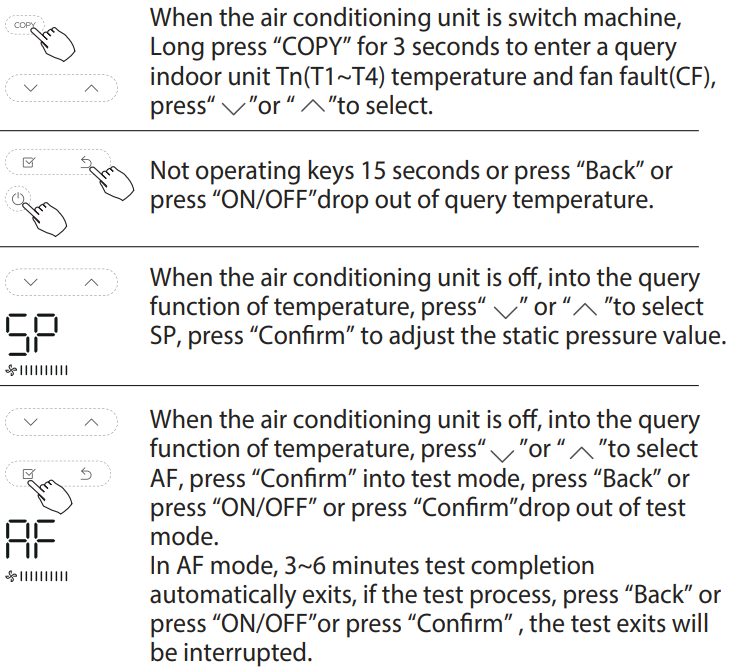
Fault alarm handing
If the system does not properly operate except the above mentioned cases or the above-mentioned malfunctions is evident, investigate the system according to the following procedures.
|
NO. |
MALFUNCTION & PROTECTION DEFINE |
DISPLAY
DIGITAL TUBE |
| 1 | Error of communication between wire controler and indoor unit |
- The error displayed on the wire controller are different from those on the unit. If error code appears, please check the <<Owner’s And Installation Manual>>and<<SERVICE Manual>>.
Technical indication and requirement
- EMC and EMI comply with the CE certification requirements.
Queries and settings
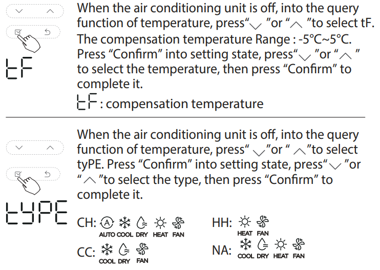
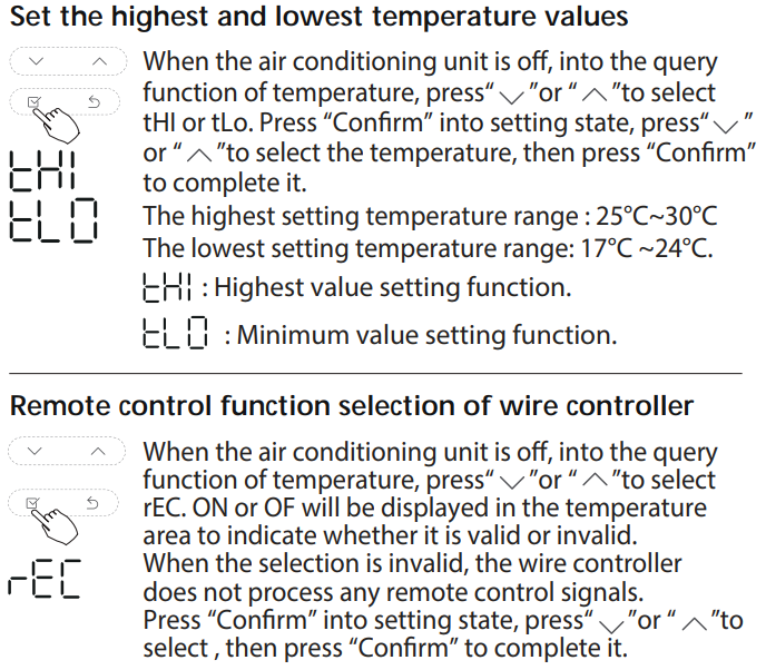
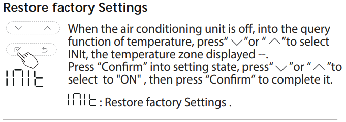
After the wired controller resumes the factory parameter setting, compensation of body temperature is uncompensated; COOL and HEAT/single COOL mode is restored to COOL and HEAT model; The temperature range was restored to 17 °C~30°C. The remote receiving function is restored to be effective.
The design and specifications are subject to change without prior notice for product improvement. Consult with the sales agency or manufacturer for details.
Reference
Download Manual
Pioneer TST-MLD-I-WP24 REMOTE CONTROL Programmable THERMOSTAT Owner Manual
Pioneer TST-MLD-I-WP24 REMOTE CONTROL Programmable THERMOSTAT Owner Manual